Transcription
PerkinElmer’sElectronicLeak Detector(part number N9306089)Instruction Manual
2008The PerkinElmer logo and design are registered trademarks of PerkinElmer, Inc
PerkinElmer Electronic Leak DetectorTa b l e o f Co n t e n t sPa g e1.0 Introduction .22.0 Battery Charging .33.0 Powering Up .34.0 Zeroing the Unit .35.0 Prior to Operation .46.0 Detecting Leaks .47.0 Specifications .48.0 Maintenance .59.0 Troubleshooting .610.0 Technology of the Unit .711.0 Interpretation of Results .812.0 Service .9www.perkinelmer.com/supplies1
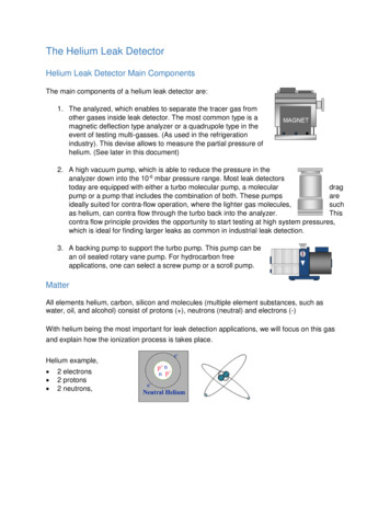
Operating Instructions1.0 IntroductionPerkinElmer’s portable Leak Detector is specifically designed for use with gaschromatography (GC) systems. It detects minute leaks of any gas with athermal conductivity different from air. The reference gas inlet (Figure 1)draws in ambient air for comparison to air drawn into the sample probe. Aleak is indicated by both an LED light display and an audible alarm.2www.perkinelmer.com/supplies
2.0 Battery Charging:Only use the universal charger provided. The Leak Detector should be fully charged prior to use. When the unit’s charge is low, thegreen battery indicator LED light will begin to blink when the unit is powered up (Figure 1). The Leak Detector cannot be used duringthe charging cycle.Unit status while engaged withthe wall chargerPre-charge qualification(immediately following plug-in)Unit is chargingUnit is fully chargedCharge LEDCondition1Hz flashContinuous onOff3.0 Powering UpNOTE: Replacement of the rechargeable cells in this unit is performed at the factory.There are no serviceable parts in this unit. Opening the case or tampering with theinternal parts will void the factory warranty.Figure 1 Leak Detector schematic.Depress and hold the power button (Figure 1) until the unitresponds with the wake-up mode. The leak detector will runthrough a self-calibration sequence for approximately 15seconds. During this time DO NOT attempt to zero the unit.4.0 Zeroing the UnitAfter the LED lights stop flashing, the unit is ready for use. Theinstrument may need to be zeroed periodically between uses,especially if it is moved from room to room, or between areas ofdiffering temperature or humidity. Do not attempt to zero theunit while the probe is stored in the holder. The probe MUST beremoved from the storage container before zeroing the unit. Tore-zero, press the Zero switch. The unit will run a self-calibrationsequence for approximately 4 seconds. When all LED lights stopflashing and the green LED light is lit, the unit is ready for use.NOTE: To avoid false readings, do not attempt to use the unit while the self-calibration sequence is in progress.www.perkinelmer.com/supplies3
5.0 Prior to OperationVerify the operation of the Leak Detector before each use by sampling gas from a GC split vent, or other source of hydrogen orhelium. Also, visually inspect the probe tip, reference gas inlet, and exhaust port for obstructions (Figure 1).IMPORTANT: Fittings being checked must be clean and dry; liquid leak detecting agents, dust, and other debris may damagethe Leak Detector if drawn into the probe.The Leak Detector responds to almost any gas you can smell, and many gases that you can’t smell. Solvent vapors, split ventexhaust, or even strong air currents around the probe or reference inlet can cause instability or false positive readings. Becareful not to breathe into the reference inlet when checking for leaks or to cover/block the inlet with your hand.6.0 Detecting LeaksSlowly move the probe tip around fittings and other potential leak sources. If the Leak Detector senses a gas other than air, theLED bar graph will begin to light, and an alarm will sound when the last LED light illuminates. The red LED lights indicatehelium and hydrogen leaks. The yellow LED lights indicate a nitrogen, argon, or carbon dioxide leak. Remove the probe fromthe vicinity of the leak and allow the unit to return to zero. If a large amount of gas has entered the probe, it may take a fewseconds for the instrument to clear itself. Please do not attempt to zero the unit while it is clearing out the gas from the probe.This may cause the unit to malfunction. Place the probe near the leak again to confirm its location. The reference gas inlet(Figure 1) must not be restricted or the unit will not operate correctly. Similarly, the exhaust port allows the gas being tested toexit the Leak Detector and must remain unobstructed. The exhaust port is located in the probe docking station.CAUTION: This unit is NOT designed for determining leaks of combustible gases. A combustible gas detector should be usedfor determining combustible gas leaks in a hazardous environment.7.0 SpecificationsPower Rating: 12 Volts DC (battery charger supplied)Battery Rating: 6 hours normal operationOperating Temp. Range: 32 –120 F (0 –48 C)Humidity Range: 0–97%4Warranty: One year warranty.Certifications: CE and JapanCompliance: WEEE, RoHSwww.perkinelmer.com/supplies
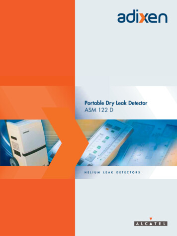
8.0 MaintenanceAvoid spilling liquids onto the unit or it may malfunction. If a liquid is spilled onto the unit, turn off the power immediately, remove heavy liquids with a dry towel, and let the unit sit until the liquid dries. Dust and debris can enter the probetip of the Leak Detector and, over time, can clog the small-bore tubing inside the unit. To prevent this, clean the probe tipperiodically. To clean the probe tip, unscrew the cap to expose the brush (Figures 2 and 3). Gently clean the probe, using asmall brush or your fingers to remove dust and debris, then replace the cap. Do not use liquids to clean the probe. Liquidscan damage the Leak Detector if drawn in through the probe.Information on where to have the unit sent for maintenance or service is listed at the end of this document.Figure 2 Cap unscrewedand partially removed.www.perkinelmer.com/suppliesFigure 3 Cap removed,exposing probe tip brush forcleaning.5
9.0 TroubleshootingProblemPossible CauseSuggested SolutionProbe cloggedClean the probe tip to remove any debrisProbe line puncturedVisually inspect probe line for holes*Weak batteryRecharge or return to PerkinElmer for batteryreplacement*Response decreasedDetector not zeroedRe-zero detectorLED bar graph stays lit during operationDetector re-zeroed before unit was purged outAllow adequate time for detector to purge, thenre-zeroReference gas inlet covered by hand orother objectRemove obstructionSensitivity decreased*Contact PerkinElmer or your PerkinElmer representative for return instructions for servicing a damaged unit. Additionalcharges may apply if the warranty has expired or the unit is damaged due to misuse.6www.perkinelmer.com/supplies
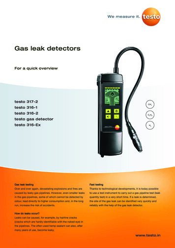
10.0 TechnologyThe Leak Detector measurement is based on thermal conductivity comparisons between the probe air and a reference air. Thedevice employs a dual thermistor technology which measures the ratio of [probe]:[reference] heat exchange values and displays the results on an LED scale (Figure 4). Under ideal operating conditions, a ratio of 1:1 indicates identical air samples forboth [probe] and [reference], and therefore no leak is present.Figure 4 Schematic layout of the Leak Detector technology.LEFT: Dual analysis is achieved with heaterelements positioned in separate flow chambers.RIGHT: Probe and reference air streams aresimultaneously monitored for thermalconductivity. Differences in air compositionare indicated by differences in the heaterelement currents.Because of slight differences in air temperature and/or humidity between the reference inlet (Figure 1) and the probe tip, asmall response indicated by a single red or yellow LED light is generally insufficient to positively identify a gas leak. Small tomoderate leaks are reliably indicated with four red LED lights, larger leaks are indicated with all red LED lights or yellow LEDlights lit and the continuous alarm is audible.www.perkinelmer.com/supplies7
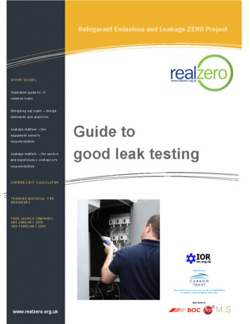
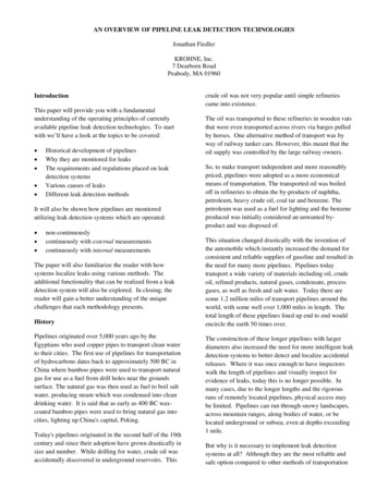
11.0 Interpreting the ResultsFigure 5 illustrates the Leak Detector’s LED light responserange. The greater the number of red or yellow LED lights litcorrelates in general to the size of the leak. NOTE: The LeakDetector is not a quantitative device, rather it is designed todetect leaks in gas line connections commonly associated withlaboratory equipmentGasHeliumHydrogen**NitrogenArgonCarbon dioxideMinimum DetectableLeak Rate(atm cc / sec.)1.0 x 10-51.0 x 10-51.4 x 10-31.0 x10-41.0 x 10⁻⁴IndicatingLED LightColorRedRedYellowYellowYellowFigure 5 LED light response chart for the Leak Detector. A 1:1 ratio of IProbe : IReference indicates no leak present. Red LEDlights indicate the presence of one or more of the following gases: helium or hydrogen. Yellow LED lights indicate thepresence of one or more of the following gases: nitrogen, argon, or carbon dioxide.**This unit is NOT designed for determining leaks of combustible gases. A combustible gas detector should be used for determining combustible gas leaks in ahazardous environment.8www.perkinelmer.com/supplies
Tip driftTip drift is the phenomenon when a false LED light response is registered as the unit is quickly turned or swept in dramaticarc movements. Tip drift is inherent to all dual thermistor leak detector technology and is based in large part on the asymmetry of the flow cells; shaking or tipping the unit influences the air flow profiles which impacts the rates of heat exchange. If thedevice is functioning normally, the LED light signal will return to zero in 3-5 seconds after the unit is held still. In extremecases, the unit may require another ‘zero’ cycle before using. To avoid tip drift, be sure to hold the unit steady while makingmeasurements.12.0 ServiceThe PerkinElmer Leak Detector carries a one year limited warranty from time of purchase. Please have the Leak Detector serialnumber available when calling PerkinElmer with any concerns you may have. Additional charges may apply if the warranty isexpired or the damage is due to misuse.Expected battery lifetime is two years from time of purchase. Customers will need to return the unit to PerkinElmer for batteryreplacement. At that time, preventative maintenance services can also be performed on the unit. A fee will be charged forservicing the unit.For questions, problems, repair services:Within the USA:Call PerkinElmer’s Technical Support at 800-762-4000For a complete listing of our global offices:Visit supplies9
Call Technical Support at 800-762-4000 (USA) or 800-561-4646 (Canada)8:30am–5:00pm EST, if you have any questions about this product.PerkinElmer LAS710 Bridgeport Avenue, Shelton, CT 06484-4794Phone: (800) 762-4000; outside the US ( 1) 203-762-4000Fax: (203) 944-4902#PE204-07 [006] Date: 7/08
Figure 5 illustrates the Leak Detector's LED light response range. The greater the number of red or yellow LED lights lit correlates in general to the size of the leak. NOTE: The Leak Detector is not a quantitative device, rather it is designed to detect leaks in gas line connections commonly associated with laboratory equipment