Transcription
DRIFTERPLOW-IN-A-BOXASSEMBLY / OWNER’S MANUALPart No: 10-0550 2017 Kolpin Outdoors Inc.REV02
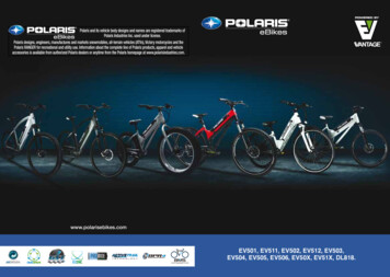
OPERATING INSTRUCTIONSCongratulations! You’ve just purchased one of the industry’s top plow systems. The DRIFTER Plow System works great for all typesof plowing. With proper care and maintenance, your plow system will last for many years!The DRIFTER Plow system is easily assembled and attaches to your ATV using a patented, unique Forward Mount system. It isdesigned to fit most models with 200cc or larger engines. The blade pivot design allows the operator to select multiple angled left-orright positions, and also incorporates a spring-loaded ’trip’ system that allows the blade to handle impacts with small obstructions.The patented 52” (132 cm) Poly Blade Assembly allows for quality snow moving capacity and snow roll-over characteristics.Additionally, this system will handle light to medium-duty summer landscape work.NOTICEThe DRIFTER Plow Systemincludes these components: 52” (132 cm) Poly Bladeand Blade Hinge Pivot Assembly Forward Mount Push Tube Universal Forward Mount SystemPlow operation requires anadditional component for operation:Winch Kit, Electric Lift or Manual Lift **These components may be specific to your vehicle.PUSH TUBE ENGAGEMENT: Place push tube under the ATV as shown and insert into the left and right channels of theassembled Forward Mount Weldment, Item #1. Fasten the push tube to the mount with supplied lock pins, Item #13.1Push Tube13ATTACH LIFTING HOOK OR ELECTRIC LIFT: Attach the lifting hook from a winch or manual lift kit to the push tube asshown. If using an electric lift kit, install the electric lift at the hole locations shown.Install lift hook or kit at this location only 2017 Kolpin Outdoors Inc.2REV02
Please read and understand all assembly instructions, notices and warnings before assembling and operating your plow system.Follow these guidelines to ensure satisfactory operation: Read this manual and your ATV operators manual before use. The plow skids are adjustable. General skid setting is even with the plow wear bar bottom edge, higher settings reduce thechance of rocks and gravel from being collected. See Page 9 for more information. To increase traction during plow operation, operators can try: Securing weight to the ATV for additional tire downforce, reducingtire air pressure, or installing tire chains.Periodically check for wear and tightness of all fasteners. Replace or re-torque fasteners as necessary.Before first use, set plow in the furthest right or left angled position to check for clearance between the plow and front tires.Operate with extreme caution on slopes and rough terrain. Be familiar with the area before you plow.Be aware of immovable objects that could be hidden in the area you are plowing.To avoid damage when pushing snow into a pile, reverse direction before raising the plow blade.Do not ram the plow blade into piles of snow.For best results, set the suspension preload of your ATV to the stiffest setting.To reduce steering effort and increase mobility, set the air pressure of your tires to the maximum pressure specification.The plow blade assembly is designed to “trip” when it strikes an object or digs in too far. When pressure is released, the plowsprings back into position. Spring tension can be increased by tightening the locknuts on the bottom of the eyebolts. For lessspring tension, loosen the locknuts.SAFETY INFORMATIONOur plow systems were designed with your safety in mind. Please read and understand all Cautions, Notices and Warnings in thismanual before you begin. In order to protect you and your ATV, certain parts of the plow system and/or hardware are designed to failwhen the equipment is over-stressed.WARNINGTo avoid personal injury or damage to your vehicle:Do not exceed 5 mph (8 kph) with the blade installedBe aware that vehicle ground clearanceis reduced with plow system installedKeep yourself, other people and pets away from theblade and moving parts during operationBefore adjusting blade angle or disconnecting the plowsystem, stop the ATV engine and set the parking brakeRemove your plow system before trail ridingWARNINGTo avoid personal injury or damage to your vehicle:Do not install forward mount system over plastic guardcomponents, which can compress over time and loosenthe installation, resulting in poor product performanceand/or damage to the ATV.Do not allow forward mount system to interfere with ATVoperational items such as brake lines, coolant hoses,control cables, steering or any other function. 2017 Kolpin Outdoors Inc.3REV02
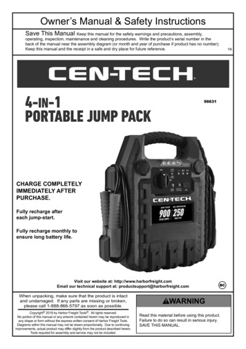
Model Number 10-0550Hardware Pack # 12-0400Parts List 1 of 3PARTS ORDERING INFORMATION:Replacement fasteners are common-type and can be purchasedlocally. Use minimum Metric 8.8 or SAE Grade 5 fasteners. 2017 Kolpin Outdoors Inc.4REV02
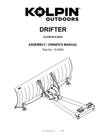
Model Number 10-0550Hardware Pack # CYC1010Parts List 2 of 3PARTS ORDERING INFORMATION:Replacement fasteners are common-type and can be purchased locally. Useminimum Metric 8.8 or SAE Grade 5 fasteners. 2017 Kolpin Outdoors Inc.5REV02
Model Number 10-0550Hardware Pack # HK-124Parts List 3 of 3PARTS ORDERING INFORMATION:Replacement fasteners are common-type and can be purchasedlocally. Use minimum metric 8.8 or SAE Grade 5 fasteners. 2017 Kolpin Outdoors Inc.6REV02
2017 Kolpin Outdoors Inc.7REV02
2017 Kolpin Outdoors Inc.8REV02
2017 Kolpin Outdoors Inc.9REV02
2017 Kolpin Outdoors Inc.10REV02
2017 Kolpin Outdoors Inc.11REV02
2017 Kolpin Outdoors Inc.12REV02
BEFORE YOU BEGIN:TOOLS REQUIRED: Please read and understand all instructions. Basic Hand Wrench and Socket Set Verify all parts and tools are accounted for. Torque Wrench To ensure a satisfactory installation, follow all stepscorrectly and in the sequence described. Plastic Cutting Tool All directions referring to right and left are when therider is sitting on the machineINSTALLATION NOTES:NOTICENOTICEDepending on application, some trimming of plastic guardsor panels may be required to install the Forward Mount.Refer to Installation Option A, B, C or D for Forward Mountinstallation, depending on your application.NOTICEPosition fasteners of the Forward Mount against thePosition mount fasteners as shown to create a wedge clampforce at the frame ‘Y’ATV FRONTINCORRECT 2017 Kolpin Outdoors Inc.13REV02
OPTION A - GENERIC MOUNT INSTALLATION FOR ROUND TUBE FRAME ATVs1.Position the Back Plate, Item #2, on top of the Forward Mount Weldment, Item #1, as shown in Illustration 1.NOTICEDepending on application, some trimmingof plastic guards or panels may be required.2.Position the forward mount weldment and back plate under the frame tubes at the “Y” location as shown in Illustration 1.3.Fasten the mount and back plate using U-bolts, washers and locknuts, Items #4, #5 and #6. Do not torque fasteners at this time.4.Position the mount and fasteners at a point on the frame that allows the push tube to be attached, but will not interfere withoperation of the ATV.5.Once the mount position has been determined, position U-bolts to the frame tube walls as close as possible and torque tospecification.FASTENER TORQUE:30 ft. lbs. (41 Nm)GENERIC ROUND TUBE FRAME SECTION4215ATV FRONT6ILL. 1 2017 Kolpin Outdoors Inc.14REV02
OPTION B - GENERIC MOUNT INSTALLATION FOR SQUARE TUBE FRAME ATVsNOTICEDepending on application, some trimmingof plastic guards or panels may be required.1.Position the Forward Mount Weldment, Item #1, under the frame tubes at the “Y” location as shown in illustration 2.2.Position the Back Plate, Item #2, on top of the frame tubes at the “Y” location as shown in Illustration 2.3.Place spacers, Item #7, between the mount and back plate. Loosely fasten the mount and back plate using bolts, washers andlocknuts, Items #9, #6 and #7. Do not torque fasteners at this time.4.Position the mount and fasteners at a point on the frame that allows the push tube to be attached, but will not interfere withoperation of the ATV.5.Once the mount position has been determined, push the spacers and fasteners to the frame tube walls as close as possible.Torque to specification. REFER TO INSTALLATION NOTES - PAGE 13.FASTENER TORQUE:30 ft. lbs. (41 Nm)32517ATV FRONT56ILL. 2 2017 Kolpin Outdoors Inc.15REV02
OPTION C - MOUNT INSTALLATION: POLARIS 400/500/800 H.O. ATVs1.Position the Forward Mount Weldment, Item #1, under the frame tubes at the “Y” location as shown in Illustration 1.2.IMPORTANT: To keep the mount level and clear the built-in rock guard extrusion on Sportsman HO ATVs, add spacers, Item#3 to the forward channel of the mount. Loosely fasten the spacers between the mount and rock guard with bolts, washers andlocknuts, Items #9, #6 and #7. Do not torque fasteners at this time. See Illustration 3.3.Position the Back Plate, Item #2, on top of the frame tubes at the “Y” location as shown in Illustration 3.4.Place spacers, Item #3, between the mount and back plate. Loosely fasten the mount and back plate using bolts, washers andlocknuts, Items #9, #6 and #7. Do not torque fasteners at this time.5.Once the mount has been positioned, orientate fasteners, to the frame tube walls as close as possible and torque to specification.REFER TO INSTALLATION NOTES - PAGE 13.FASTENER TORQUE:30 ft. lbs. (41 Nm)POLARIS H.O. FRAME SECTION29617436867ROCK GUARDATV FRONTILL. 3 2017 Kolpin Outdoors Inc.16REV02
STEP 5 - ATTACH PLOW SYSTEM TOTHE FORWARD MOUNT:1. Refer to Operating Instructions, Page 2 & 3.2. Once the plow system is attached to your ATV andthe plow blade is on the ground, adjust the bladestops and blade spring tension as desired to achievebest performance. Refer to page 10 illustration 7 & 8.3. Once the desired blade position is obtained, torquethe blade stop fasteners to specification.FASTENER TORQUE:17ft. lbs. (23 Nm) 2017 Kolpin Outdoors Inc.17REV02
One Year Limited WarrantyFor the period of one (1) year from the purchase date, Kolpin will replace for the original purchaser,free of charge, any part or parts found upon examination by Kolpin to be defective in material,workmanship, or both.All transportation costs incurred submitting product to Kolpin for warranty consideration must beborne by the purchaser. If Kolpin determines that the product must be returned to the factory forcredit, please call 1-877-956-5746 for a Return Merchandise Authorization (RMA) number andshipping instructions.This warranty does not apply to parts that have been damaged by accident, alteration, abuse,improper maintenance, normal wear, or other causes beyond the manufacturer’s control. In order toprotect you and your ATV, certain parts of the plow system and/or hardware are designed to failwhen the equipment is over-stressed. Parts that are lost due to loosening and impropermaintenance are not covered under warranty. This warranty does not cover removal or reinstallationlabor fees of the plow system and related components.Peripheral products such as engines, electric motors, and actuators may carry an originalmanufacturer’s warranty. Most hardware is general in nature and is easily obtained locally. Be sureto replace with minimum metric class 8.8 specification.Kolpin Outdoors, Inc.Telephone: (763)-478-5800Toll Free: (877)-956-5746Fax Number: (800)-245-7569www.kolpin.comEmail: customerservice@kolpin.com 2017 Kolpin Outdoors Inc.18REV02
Congratulations! You've just purchased one of the industry's top plow systems. The DRIFTER Plow System works great for all types of plowing. With proper care and maintenance, your plow system will last for many years! The DRIFTER Plow system is easily assembled and attaches to your ATV using a patented, unique Forward Mount system.