Transcription
Structural Analysis - IIIIntroduction toMatrix Methods
Module IMatrix analysis of structures Definition of flexibility and stiffness influence coefficients –development of flexibility matrices by physical approach &energy principle.Flexibility method Flexibility matrices for truss, beam and frame elements –load transformation matrix-development of total flexibilitymatrix of the structure –analysis of simple structures –plane truss, continuous beam and plane frame- nodal loadsand element loads – lack of fit and temperature effects.2
Force method and Displacement method These methods are applicable to discretized structuresof all types Force method (Flexibility method) Actions are the primary unknowns Static indeterminacy: excess of unknownactions than the available number of equationsof static equilibrium
Displacement method (Stiffness method) Displacements of the joints are the primaryunknowns Kinematic indeterminacy: number ofindependent translations and rotations (theunknown joint displacements) M ore suitable for computer programming
Types of Framed Structures a. Beams: may support bending moment, shear force andaxial force b. Plane trusses: hinge joints; In addition to axial forces, amember C A N have bending moments and shear forces if ithas loads directly acting on them, in addition to joint loads
c. Space trusses: hinge joints; any couple acting on amember should have moment vector perpendicular to the axisof the member, since a truss member is incapable ofsupporting a twisting moment d. Plane frames: Joints are rigid; all forces in the plane ofthe frame, all couples normal to the plane of the frame
e. G rids: all forces normal to the plane of the grid, allcouples in the plane of the grid (includes bending andtorsion) f. Space frames: most general framed structure; maysupport bending moment, shear force, axial force andtorsion
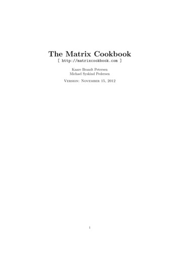
Deformations in Framed StructuresThree forces: N x ,V y ,VzThree couples:Tx , M y , M z Significant deformations in framed structures:StructureSignificant deformationsBeamsflexuralPlane trussesaxialSpace trussesaxialPlane framesflexural and axialGridsflexural and torsionalSpace framesaxial, flexural and torsional
Types of deformations in framed structuresb) axial c) shearing d) flexural e) torsional9Dr.RajeshKN
Static indeterminacy Beam: Static indeterminacy Reaction components - number ofeqns availableE R 3 Examples: Single span beam with both ends hinged withinclined loads C ontinuous beam Propped cantilever Fixed beam
Rigid frame (Plane): External indeterminacy Reaction components - number ofeqns availableE R 3 Internal indeterminacy 3 closed framesI 3a Total indeterminacy External indeterminacy Internal indeterminacyT E I R 3 3a N ote: An internal hinge will provide an additional eqn12
Example 1T E I R 3 3a 2 2 3 3 0 1Example 3T E I R 3 3a 3 2 3 3 3 12Example 2T E I R 3 3a 3 3 3 3 2 12Example 4T E I R 3 3a 4 3 3 3 4 21
14
Rigid frame (Space): External indeterminacy Reaction components - number ofeqns availableE R 6 Internal indeterminacy 6 closed framesExample 1T E I R 6 6a 4 6 6 6 1 24If axial deformations are neglected, static indeterminacy isnot affected since the same number of actions still exist inthe structure
Plane truss (general): External indeterminacy Reaction components - number of eqns availableE R 3 Minimum 3 members and 3 joints. A ny additional joint requires 2 additional members. Hence, number of members for stability,m 3 2 j 3 2 j 3
Hence, internal indeterminacy,I m 2 j 3 Total (Internal and external) indeterminacyT E I R 3 m 2 j 3 m R 2j m R j: number of members: number of reaction components: number of joints N ote: Internal hinge will provide additional eqn17
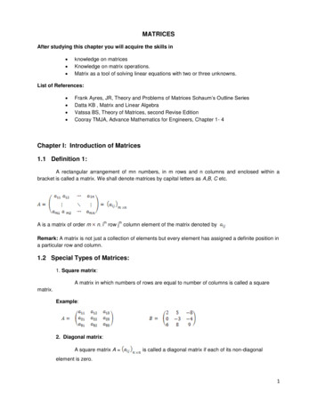
Example 1T m R 2 j 9 3 2 6 0E R 3 3 3 0I T E 0Example 2T m R 2 j 15 4 2 8 3E R 3 4 3 1I T E 2Example 3T m R 2 j 6 4 2 5 0E R 3 1 4 4 0I T E 0Hinge at A
Example 4T m R 2 j 7 3 2 5 0E R 3 3 3 0I T E 0Example 5T m R 2 j 6 4 2 4 2E R 3 4 3 1I T E 1Example 6T m R 2 j 11 3 2 6 2E R 3 3 3 0I T E 2
Wall or roof attached pin jointed plane truss (Exceptionto the above general case): Internal indeterminacy I m 2 j External indeterminacy 0 (Since, once the memberforces are determined, reactions are determinable)Example 1T I m 2 j 6 2 3 0Example 2T I m 2 j 7 2 3 1Example 3T I m 2 j 5 2 1 320
Space Truss: External indeterminacy Reaction components number of equations availableE R 6 Total (Internal and external) indeterminacy T m R 3 jExample 1 Total (Internal and external) indeterminacyT m R 3j T 12 9 3 6 3E R 6 9 6 3
Actions and displacements Actions: External actions (Force or couple or combinations) and Internal actions (Internal stress resultants – BM, SF, axialforces, twisting moments)22
Displacements: A translation or rotation at some point Displacement corresponding to an action: Need not be causedby that action
Notations for actions and displacements:D32D33
Equilibrium Resultant of all actions (a force, a couple or both) must vanishfor static equilibrium Resultant force vector must be zero; resultant moment vectormust be zero Fx 0 Fy 0 Fz 0 Mx 0 My 0 Mz 0 For 2-dimensional problems (forces are in one planeand couples have vectors normal to the plane), F 0x F 0y M 0z In stiffness method, the basic equations to be solvedare the equilibrium conditions at the joints
Compatibility Compatibility conditions: Conditions of continuity ofdisplacements throughout the structure Eg: at a rigid connection between two members, thedisplacements (translations and rotations) of both membersmust be the same In flexibility method, the basic equations to be solved arethe compatibility conditions
Action and displacement equations Spring: D FA Stiffness Flexibility:A SDS F 1F S 1 The above equations apply to any linearly elasticstructure
Example 1:Flexibility and stiffness of a beam subjected to a single loadFlexibilityL3F 48EI48EIStiffness S 3L
Example 2:Flexibility coefficients of a beam subjected to several loadsA ctions on the beamDeformations corresponding to actions
Unit load applied corresponding to each action, separately30Dr.RajeshKN
D1 D11 D12 D13D2 D21 D22 D23D3 D31 D32 D33D1 F11 A1 F12 A2 F13 A3D2 F21 A1 F22 A2 F23 A3D3 F31 A1 F32 A2 F33 A3F11 , F12 , F13 etc.Flexibility coefficients Flexibility coefficient F12: Displacement corresponding to A1caused by a unit value of A2. In general, flexibility coefficient Fij is the displacementcorresponding to Ai caused by a unit value of Aj.
Example 3:Stiffness coefficients of a beam subjected to several loadsActions on the beamDeformations corresponding to actions
Unit displacement applied corresponding to each DOF, separately,keeping all other displacements zero
A1 A11 A12 A13A1 S11D1 S12 D2 S13D3A2 S21D1 S22 D2 S23D3A3 S31D1 S32D2 S33D3S11 , S12 , S13 etc.Stiffness coefficients: Stiffness coefficient S12: Action corresponding to D1 caused bya unit value of D2. In general, stiffness coefficient Sij is the action correspondingto Di caused by a unit value of Dj.
Example 4: Flexibility and stiffness coefficients of a beamFlexibility coefficients:
Stiffness coefficients:
Example 5: Flexibility and stiffness coefficients of a truss
Flexibility and stiffness matrices1. Flexibility matrixoThe compatibility equations are:D1 F11 A1 F12 A2 F13 A3 . F1n AnD2 F21 A1 F22 A2 F23 A3 . F2n An.Dn Fn1 A1 Fn2 A2 Fn3 A3 . Fnn AnoIn matrix form,F11 D1 D2 F21 . . Fn1 D n n 1F12F22.Fn2n n. F1n A1 A . F2n 2 . . . . Fnn An n 1
D FA D F A {D}Displacement matrix (vector),[F]Flexibility matrix,{A}A ction matrix (vector)Fij are the flexibility coefficients
2. Stiffness matrixoThe equilibrium equations are:A1 S11 D1 S12 D2 S13 D3 . S1n DnA2 S21 D1 S22 D2 S23 D3 . S2n Dn.An S n1 D1 S n2 D2 S n3 D3 . S nn DnoIn matrix form,S11 A1 A2 S21 . . S A n n1n 1S12S 22.S n2n n. S1n D1 . S2n D 2 . . . . Snn Dn n 140Dr.RajeshKN
A SD A S D {A}Action matrix (vector) ,[S]Stiffness matrix,{D}Displacement matrix (vector)Sij are the stiffness coefficients Relationship between flexibility and stiffness matricesA S D S F A F S 141Dr.RajeshKN
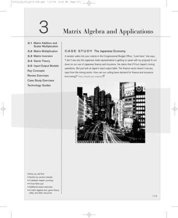
Example: Cantilever elementL3F11 ;3EI2L;F LF21 F12 2EI 22 EIL3L2D1 A1 A23EI2EIL2LD2 A1 A22EIEI L3 D1 3EI 2 D2 L 2EIL2 A1 2EI L A2 EI F
12EIS11 3 ;L 6EIS21 S12 2 ;LA1 12EI6EID D2132LLA2 6EI4EID D212LL 6EI 1L2 D 4EI D2 L 12EI A 1 L3 A2 6EI L21 F S S F 0 0 I 1 4EIS22 L S
Flexibility matrix and stiffness matrix are relating actions andcorresponding displacementsThe flexibility matrix F obtained for a structure analysed byflexibility method may not be the inverse of the stiffness matrix obtained for the same structure analysed by stiffness methodbecause different sets of actions and corresponding displacementsmay be utilized in the two methods. S
Equivalent joint loads Analysis by flexibility and stiffness methods requires that loadsmust act only at joints. Thus, loads acting on the members (i.e., loads that are not actingat the joints) must be replaced by equivalent loads acting at thejoints. The loads that are determined from loads on the members arecalled equivalent joint loads.
Equivalent joint loads are added to the actual joint loads to getcombined joint loads. Analysis carried out for combined joint loads Combined joint loads can be evaluated in such a manner thatthe resulting displacements of the structure are same as thedisplacements produced by the actual loads This is achieved thru the use of fixed end actions to getequivalent joint loads
Example 1Beam with actual applied loadsApplied joint loads
Applied loads other than joint loads(To be converted to equivalent joint loads)
Member fixed end actions(Due to applied loads other than joint loads )Fixed end actions for the entire beam
Equivalent joint loads (Negative of fixed end actions)Combined joint loads(Applied joint loads Equivalent joint loads)50
Fixed end actionsMMb 2a b l2aMa 2b a 2lb6Mabl36Mabl3MM4l23M2lM4l23M2l
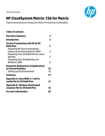
Example 240 kN/ m120 kNAB 4m20 kN/mDC12 m12 mwl 2 48012480wl 2402240213.3312 m240240120120106.67Fixed end actions88.8931.1152
480A240266.67B240 88.89 328.89133.33C120 31.11 151.11240D120Equivalent joint loads(Opposite of fixed end actions)Combined joint loads are same as equivalent joint loads here,since there are no loads applied to joints directly
Superposition of combined joint loads and restraint actions givesthe actual loads. Superposition of joint displacements due to the combinedjoint loads and restraint actions gives the displacementsproduced by the actual loads. But joint displacements due to restraint actions are zero.Thus, joint displacements due to the combined joint loads givethe displacements produced by the actual loads But member end actions due to actual loads are obtained bysuperimposing member end actions due to restraint actions andcombined joint loads
SummaryMatrix analysis of structures Definition of flexibility and stiffness influence coefficients –development of flexibility matrices by physical approach &energy principle.
Module I Matrix analysis of structures Definition of flexibility and stiffness influence coefficients - development of flexibility matrices by physical approach & energy principle. Flexibility method Flexibility matrices for truss, beam and frame elements - load transformation matrix-development of total flexibility