Transcription
REVISED EDITION 2017ACCESSIBLEBUS STOP DESIGNGUIDANCEMAYOR OF LONDON
02 Accessible Bus Stop Design GuidanceContentsContentsThe Accessible Bus Stop Design Guidance setsout requirements and guidance for the design ofaccessible bus stop environments. It should beused by those who shape the environment throughplanning and street design as well as engineersdesigning bus-specific infrastructure.1Introduction.042Accessible bus services.103Bus stop location.144Passenger waiting area.195Bus stop area.256Bus stop layouts.277Bus boarders.30 Streetscape Guidance8Bus bays.34 London Pedestrian Design Guidance9Kerb profiles and heights.36 London Cycling Design Standards10Cycle facilities.38 Kerbside Loading Guidance11Other considerations.43 Station Public Realm Urban Design Guidance12References/data sources and Appendix.46This document forms one part of Transport forLondon’s Streetscape Toolkit, and should be read inconjunction with other TfL guidance documents:Published by Transport for London, 2017
03 Accessible Bus Stop Design GuidanceFiguresFiguresFigure 1Street Types for London.07Figure 13Exit side of pedestrian crossing.29Figure 2Features of the bus stopenvironment.08Figure 14Exit side of junction.29Figure 3Passenger groups benefiting fromlow-floor buses.Figure 15Full-width boarder.3111Figure 16Alternative full-width boarder layouts.31Figure 4Bus stop layout objectives.12Figure 17Multiple bus full-width boarder.31Figure 5Relationship between buses and kerbs.13Figure 18Half-width boarder.32Figure 6Considerations for bus stop locations.15Figure 19Amended bus bay.35Figure 7Bus arrival patterns.16Figure 20Filled-in bus bay with parking/loading.35Figure 8Centre of path layout.21Figure 21Half-filled bus bay.35Figure 9Back to kerb layout.21Figure 22Mandatory cycle lane at bus stop.39Figure 10Back of path layout.21Figure 23Indicative bus stop bypass layout.41Figure 11Boarding and alighting zones.22Figure 12Kerbside approach with parking onapproach and exit.28
04 Accessible Bus Stop Design Guidance1.Introduction IntroductionThis chapter provides an introduction to theguidance and a summary of the key requirementsto achieve an ‘Accessible bus stop’.BUSSTOPBUSSTOP
05 Accessible Bus Stop Design Guidance1. INTRODUCTIONEvery day in London 1.3 million journeys aremade by customers with disabilities, 700,000journeys are made by people aged over 75, nearlyfive million journeys are made by passengerscarrying heavy luggage and 1.5 million by peoplewith small children. Ensuring that the Londonbus network continues to be accessible forall Londoners, is critical for London’s futureeconomic prosperity and social cohesion.There are many different user groups whohave different needs with regard to bus stopdesign. Specific user groups that need specialconsideration include those customers that usea wheelchair, have limited mobility, are blindor visually impaired, are hearing impaired, havelearning difficulties and the elderly. It is alsoimportant that designers consider these differentuser needs such as those who use wheelchairs,crutches, walking sticks, canes, guide dogs,mobility scooters, shopping trolleys, and buggiesaccessing bus services.This guide updates the ‘Accessible Bus StopGuidance note BP1/06’ published in January 2006and its predecessor documents. These updatedguidelines have been developed in the contextof the Equality Act 2010, the Mayor’s TransportStrategy and the Accessibility Implementation Plan.This intention of this guidance is to helpencourage all those involved in the design,Introductionconstruction and operation of London’s roadsto consider the different accessibility needs ofLondoners who use the TfL bus network. Theimportance of an accessible bus service willincrease as the number of older and disabledLondoners is projected to rise significantly. Revised criteria for an accessible bus stopThis document updates the original accessibilityguidance to ensure it is both relevant andreflects changes in policy. Key additions include: Removal of references to articulated busesand particular kerb types that are not specifiedfor use by TfL New chapters on interaction of bus stops withother street facilities (‘cycle facilities’ and ‘otherconsiderations’)Key omissions include:
06 Accessible Bus Stop Design GuidanceAccessible bus stopsThis guidance, aims to provide all those involvedin the construction of bus stops with designguidance that ensures bus stops are accessibleto all, particularly disabled passengers. Thisguidance will also assist highway authorities inthe development of practical and affordablemeasures to improve accessibility at busstops that are compatible with the particularcharacteristics of low-floor buses deployed onLondon’s road network.The introduction of low-floor buses fitted withramps for wheelchair access throughout London,has led to a requirement for appropriate kerbsideaccess at bus stops. Unless all stops along a busroute are equally accessible, passengers may beunable to board or alight a bus at their desiredlocation and the potential benefits from lowfloor buses will be reduced. This hinders thepublic transport network being fully inclusive.The Equalities Act (2010) places a duty onboth public transport operators and highwayauthorities to provide reasonable adjustments sothat disabled passengers are not disadvantaged.Providing access between a low-floor bus (fittedwith ramps) and the footway, is crucial to fulfillingthese duties. It is also important to consider theneeds of other disabled groups such as blind orcognitive impaired bus passengers, as well asthose carrying heavy luggage and pushchairs.From an operational perspective, a well designedbus stop can provide significant benefits. BusIntroductionstop design and location is recognised as a keyelement in the drive to improve the quality ofbus services for all users.It is important to view the bus stop as aninterchange, rather than simply a location alonga bus route where buses stop, comprising onlya post with a flag and a cage laid on the roadsurface. Bus passengers are also pedestriansat each end of the bus trip and all elements oftheir journey should be considered includingthe convenience and comfort of the waitingenvironment.Street Types for London frameworkThe Street Types for London framework hasbeen developed in recent years in collaborationwith London’s boroughs. It takes account oflocal and network priorities and aims to helpthe consistent allocation of road space acrossLondon. The aim is to ensure consistency inapproach in considering the operation andfunction of different streets.For all Street Types accessible bus stop facilitiesshould be provided, however Street Types mayinfluence the different levels of service andcapacity will be required at bus stops.A designer can highlight where specific schemeshave been successful in encouraging betterbehaviour or more efficient use of space andassess whether a similar approach may besensible for a location with a matching StreetTypes. This translation of Street Types into aspecific response should help identify wherepeople should expect to find similar types ofinfrastructure or levels of service across London.Ultimately, the Street Types framework providesa unified view of London’s roads. Within thisframework, the individual design elements whichcumulatively influence the bus stop environmentcan be considered for each location, asillustrated in figure 1.The Street Types framework indicates how therelative significance of movement and placeinfluences the suitability of a particular designand expectations for the level of provisionrequired. As such, Street Types provide anoverarching context to discuss the suitabilityof applying the design tools defined withinthis note.
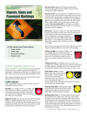
07 Accessible Bus Stop Design GuidanceIntroductionLocal significanceMovementStrategic significanceFigure 1: Street Types for Londoneg Core roadM3eg High roadeg City hubM3P1eg ConnectorM2M3P2P3eg High streeteg City streetM2P1eg Local streetM1M2P2P3eg City placeeg Town squareM1P1Local significanceM1P2P3PlaceStrategic significance
08 Accessible Bus Stop Design GuidanceFigure 1 shows how each Street Type is assigneda Movement and Place value between 1 and3; the higher the number the more strategicthe importance of the Movement or Placefunction. Accessibility of bus stops needs to beconsidered in all of these locations, althoughthe assigned Street Type can help to inform howthe bus stop will interact with the surroundingfootway and carriageway.Bus stop environmentWhen reviewing individual bus stops, and theirimmediate environment, designers need to takeaccount of the wide range of issues that arediscussed within this guidance and that eachsite is a unique location, with unique bus stopenvironment characteristics (see figure 2).Healthy StreetsHealthy Streets aim to reduce traffic, pollutionand noise, create more attractive, accessible andpeople-friendly streets where everybody canenjoy spending time and being physically active,and ultimately to improve people’s health.Providing an accessible bus network will be a keypart in achieving this ambition across London.The bus network has a critical contribution inimproving the health of Londoners, increasingphysical activity and providing access to vitalamenities. More accessible bus stops enhancethese benefits by providing more inclusive busservices, and so reducing social isolation andincreasing the number who can use these services.IntroductionFigure 2: Features of the bus stop environmentBus stop environment Security (including lighting) Bus stop post and flagSurface markings for buses Bus passenger shelter and seatingUtilities access Information (including timetablesand maps)DrainagePedestrian footwayHeight and type of kerbAdequacy of waiting areaSpace for bus to straighten Approach and exit paths for busesConnectivity with footwayConvenience for passengersThe objective is to ensure that bus stops havea fully accessible design, by using features suchas kerbside controls and bus boarders as designtools. Additionally, it is important for: Local authorities to remove obstacles aroundbus stops as footway clearance is a criteriarequired for accessibility at bus stops Planners and engineers to optimise thelocation, design and construction of bus stops Motorists and enforcement authorities torecognise the necessity for bus stops to bekept clear of parked vehicles Bus driver training to include how to approachand correctly use the bus stop; particularlywhen deploying the ramp for a wheelchair
09 Accessible Bus Stop Design GuidanceBus stop accessibilityA key TfL objective is to increase the number ofaccessible bus stops. 95% of all bus stops in Londonwill be accessible by March 2017.A bus stop must meet the following criteria to befully compliant as an accessible bus stop: Clearway in place – On borough roads a clearwayis denoted by a thick solid yellow line (Traffic SignsRegulations and General Directions (TSRGD) 1025.1), eachbus stop should have one of these along the length ofthe bus stop cage. This, in conjunction with the relevantupright sign (TSRGD Schedule 7, Part 6, Clause 1), allowsfor the enforcement of the no stopping restrictionsThe requirement for timeplates has now been removedfor roads on the Transport for London Road Network(TLRN) because the double red line at bus stop denotesno stopping Kerb 100mm – In order for a bus to deploy its rampsafely the ideal range in terms of kerb height is125-140 millimetres, however 100 millimetres is theminimum for it to be compliant Access free of impediments – A visual check of thearea around the bus stop, including the surroundingpavement be undertaken, to ensure that the bus willbe able to deploy its ramp so that wheelchair usersand people with prams can access the ramp. This isimportant in preventing visually impaired people walkinginto obstacles when boarding and alighting the busIntroduction
10 Accessible Bus Stop Design Guidance2. Accessible bus servicesThis chapter provides an overview ofhow London’s bus services are accessible.It also sets out objectives of the bus stoplayout in the design of a bus stop.Accessible bus services
11 Accessible Bus Stop Design GuidanceAccessible bus servicesof bus user groups that benefit from low floorbuses is shown in figure 3.2. ACCESSIBLE BUS SERVICESFeatures of London bus servicesLow-floor bus usersLow-floor buses reduce the height differentialbetween the kerb and bus floor, improvingaccessibility for all passengers. Mobility impairedpassengers, including wheelchair users, benefitmost from low-floor buses. When designing busstops for low floor bus access, the needs of allpassengers should be considered.Research conducted by Transport ResearchLaboratory (TRL Report 271) has shown thatpassengers with pushchairs also benefit greatlyfrom the introduction of low-floor buses. A listThe entire TfL bus network is operated usinglow-floor vehicles. All London buses have a singlestep entry, a low-floor in the front part of thevehicle, and either a sloping gangway or a steptowards the rear over the drive axle. Most buses inLondon have front doors for boarding passengersand centre doors for those alighting. It should benoted that the New Bus for London (Routemaster)has three doors, all of which are used for boardingand alighting. This includes a central door to alloweasy access for mobility passengers. Poweredramps are usually fitted to the centre door whereFigure 3: Passenger groups benefiting from low-floor busesPassengerswith shoppingor luggageOlder PeoplePeoplewith youngchildrenLow-floor bus access benefitsVisuallyimpairedpeoplePeople withpushchairsWheelchair userswheelchair users may board and alight. Pushbuttons are provided for wheelchair users to alertthe driver when the ramp needs to be deployed.Additionally, low-floor buses are provided withthe means of lowering, or ‘kneeling’, the bussuspension to reduce the step height at stops. Thisis provided at the passenger’s request. The ‘Big RedBook’, a guidance manual provided to all LondonBuses’ drivers, states that the bus should pull up asnear as possible to the kerb. Drivers are also guidedto ‘kneel’ the bus if a passenger asks or if the driverobserves a passenger requiring this facility.
12 Accessible Bus Stop Design GuidanceBus stop layout objectivesThe objectives of an ideal bus stop layout areshown in figure 4. The bus should stop parallelto, and as close to, the kerb as possible to alloweffective use of the bus’ facilities. The criticaldimensions to consider are the vertical height, orstep height, from the kerb to the bus floor andthe horizontal gap from the kerb edge to the sideof the bus. A well-designed bus stop will providefeatures which co-ordinate with the facilities ofthe low-floor bus and minimise vertical heightand horizontal gap distances.Accessible bus servicesFigure 4: Bus stop layout objectivesBus stop layout objectives A llow easy unobstructed access to andfrom the stop R emove street furniture which preventspassengers boarding and alighting A ffordable and commensurate withaccessibility benefit M inimise use of kerb space wherethere are competing demands forfrontage access A llow the bus to line up within 200mmof and parallel with the kerb P revent/dissuade other vehicles fromparking in the stop areas M inimise time spent at the busstop by the bus
13 Accessible Bus Stop Design GuidanceKerb heightsAs well as considering the bus stop layoutfor accessibility of the stop, it is important toconsider the design and height of the kerb toenable the bus ramp to be deployed safely.The size of the vertical gap between the kerband floor of the bus will affect the gradient ofthe ramp when it is deployed. If this gradientis too severe some wheelchair users may beunable to enter or exit safely from the bus. TfLrequire buses to be capable of deploying a ramp,giving a 1:8 or 12% gradient onto a kerb rangeof 100mm-140mm. This is in order to complywith the duties required under the Equality Act2010, to provide reasonable adjustments sothat disabled people are not disadvantaged.This regulation, therefore, assumes a ‘standard’kerb height of 140mm, which, although notthe case universally, is the height that vehiclemanufacturers are guided to apply in bus design.Best practice is a kerb height between 125mmand 140mm, as the ramp cannot be deployedif the kerb is too low or too high. The minimumheight for bus stop to be classified by TfL asaccessible is 100mm, whilst kerb heights above150mm are not recommended.Figure 5 shows the relationship between thebus and kerb. It is important to recognise that,when deployed on a 100mm-140mm high kerb,the gradient of the ramp may vary. The majordeterminants include the:Accessible bus servicesFigure 5: Relationship between buses and kerbs Type of ramp Ramp lengthBus floor Camber of the carriagewayVerticalgapKerbKerbheight Carriageway and footway crossfalls ‘Kneeling’ height of the bus floorHorizontalgapRoad level5.1: Critical dimensionsBus floorRampRamp gradientKerbRoad level5.2: Ramp gradientBus floorStepheightKerbRoad level5.3: Normal step heightReduction fromoriginal step heightBus floorNew step heightKerbRoad level5.4: ‘Kneeling’ step height Whether the bus is fully ladenAlthough all London Buses have the ability to‘kneel’, it should be noted that the reductionin step height achieved by ‘kneeling’ is notnecessarily uniform along the side of the bus.If the ‘kneeling’ system operates on the frontaxle alone, the front door will be lower than thecentre door. Alternative configurations includetilting of the nearside of the bus or lowering ofthe entire vehicle.Horizontal gapIn the urban environment, there can exist aconflict between the demands for frontageservicing, short-term parking and the need toprotect a sufficient length of kerb space toallow buses to easily access a stop. As withprevious guidelines, this document recognisesthe competing demands in London’s busy streetenvironment and retains the previous targetbenchmark of the bus stopping within 200mmof the kerb.
14 Accessible Bus Stop Design Guidance3. Bus stop locationThis chapter provides guidance on what should beconsidered in deciding the location of a bus stop.In particular this discusses bus stop spacing, bus cagecapacity, traffic signals and ‘hail and ride’ services.Bus stop location
15 Accessible Bus Stop Design Guidance3. BUS STOP LOCATIONThis guidance recommends that accessibilityshould be considered in terms of the wholejourney approach. Bus stops should be locatedto allow passengers to board and alight safelyand conveniently. A comprehensive network ofsuch stops should be provided ensuring thatpeople have access to their local amenitiessuch as shops, hospitals, schools and transportinterchanges. Key considerations for bus stoplocations are listed in figure 6.Bus stop locationand in particular at junctions, is convenient andhelps passengers complete the rest of theirjourney safely. For example as a minimum thesewalking routes to and from the bus stop shouldbe accessible for wheelchairs and pushchairs.The use of speed cushions particularly on theimmediate approach to, and departure from,bus stops should be avoided as there may be arisk of falling for passengers intending to alightwho are walking within the bus as it traversesthe cushion.CrossingsIt may be necessary to provide additionaldropped kerbs and/or crossing facilities as partof bus stop improvements. These type of workswill need road safety auditing, however schemesthat do not impact on the road layout will notrequire a Road Safety Audit.Figure 6: Considerations for bus stop locationsBus stop locationStop locations require agreement betweenTfL, highway authorities and the police.Residents, local businesses, local NHS or healthfacilities and the views of bus user groups andstakeholders should also be considered. D river and waiting passengers are clearlyvisible to each other Where there is space for a bus shelter Located close to key local facilitiesThis chapter outlines design considerations forbus stop locations including: L ocated close to main junctions withoutaffecting road safety or junction operation C lose to (and on exit side of) pedestriancrossings pedestrian access to bus stops (walkingroutes, crossings and gullies) L ocated to minimise walking distancebetween interchange stops optimising bus stop locations (spacing andcapacity) interaction with traffic signals non-permanent arrangements for bus stopsWalking routesConsideration should be given to the routestaken by passengers to and from the bus stop.Locating stops near pedestrian crossing facilities, ‘Tail to tail’ on opposite sides of the road Away from sites likely to be obstructed Adequate footway width
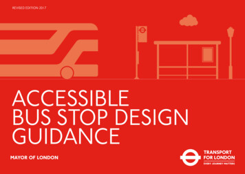
16 Accessible Bus Stop Design GuidanceGulliesWhere possible, the use of gullies in the positionof the boarding and alighting zone should beavoided or fitted with a frame to ensure that theramp, when deployed, is stable and passengers donot trip or become trapped in the event they stepinto the carriageway before stepping on the bus.Stop spacingConsideration should be given to improvingspacing, and reviewing locations according tothe movement and place function of a street,particularly where interchange is an issue. Busjourney times are affected by the number ofstops on a route and therefore a careful balancemust be achieved.This guidance recommends spacing for all busstops in local areas is considered carefully formobility impaired users (refer to the Bus NetworkPlanning Guidance). Spacing must consider thestreet’s place and movement functions andpassenger demand for use of the stop. If it isproposed to relocate stops, an assessment ofresulting benefits/impacts should be undertakenalongside consultation with stakeholders.Stop capacityRecommended bus stop capacity is a functionof bus length, service frequency, the number ofserving routes and their average dwell time. A37m kerbside bus stop cage is generally sufficientfor a frequency of 15 buses per hour (bph) butinadequate for 45 bph, where space should beBus stop locationFigure 7: Bus arrival patternsScenario A – 1 bus at the stop every 5 minutes550Scenario B – 2 buses at the stop 6 times an hour55510503530101545204020403525Scenario C – 2 buses at the stop 6 times an hour– 3 buses at the stop 2 times an hour550154503025KeyAssume start arrivals is at 12 o’clockService 1 – Bus every 5 minutes (12 bph)Service 2 – Bus every 10 minutes (6 bph)550Service 3 – Bus every 7.5 minutes (8 bph)5105015452040353025Total 26 bph assume 1 minute dwell time
17 Accessible Bus Stop Design Guidanceprovided for more than one bus to access andserve the stop at the same time. Conversely, atbus stops where the number of buses serving thestop is much lower, a shorter cage of 25 metresshould be sufficient, subject to swept pathanalysis demonstrating that a bus can achieve aposition flush with the kerb. The ‘Big Red Book’advises drivers to stop within the cage markings.Other measures of the capacity of a bus stopinclude total passenger demand, average dwelltime and ease of pulling out from the stop.Decisions on merging or splitting stops shouldtherefore be based on observations of the actualperformance of the stop rather than just lookingat buses per hour.The ‘clock-face’ diagram shown in figure 7indicates how the frequency of servicesinfluences the space required at a stop. Thisshows the estimated volume of buses at a singlebus stop, depending on the frequency of therespective services.For example Scenario C in figure 7 shows thatalthough there is a frequency of 26 bph, thestop, would theoretically operate well belowcapacity. If there is a dwell time of one minuteper bus, the stop should only be occupied for26 minutes, however the arrival pattern of busesmeans that at times more than one bus will beon the stop.It is recognised that at certain locationsthe number and frequency of bus servicesmay be particularly high, as well as multipleBus stop locationrequirements for kerbside space, and thereforecompromises may have to be made to thelength of the cage. This may impact on the bus’ability to pull up close to the kerb, so only inexceptional circumstances should cage lengthsbe shortened.It is recommended that where locations are servedby more than 25-30 bph and sufficient space isavailable, bus stops should be split. This enablesbuses on different routes to serve separatestops, thus reducing bus-on-bus delay and busstop congestion. However, it is recommendablefor bus routes with common destinations toshare the same stop, and this may result in itbeing preferable to have more than 25 bph ona stop, even where space exists to introduce asplit stop. A bus stop that has more multipleroutes with lower frequencies is likely to havemore times with multiple buses at the stop thana stop with fewer routes at a higher frequency.Bus stops and traffic signalsBus stops close to traffic signals may requiremitigating measures to retain traffic capacityat the signals; for example a central islandwith additional signal, modified lane markingsor a different traffic signals sequence. Theseare all site specific measures which requireconsultation with the relevant traffic signalsauthority. Passengers often prefer the bus stopto be as close to the junction as possible. Ideally,bus stops should be located on the exit side ofjunctions, where the effect on saturation flowsis generally less than stops sited in advance ofsignals. A bus stop in advance of the signals canhave safety implications, as a driver’s forwardvisibility will be reduced. When at a bus stop, abus can obscure the nearside signal or obscure apedestrian leaving the footway to cross the road.There are locations where a bus stop is betterlocated on the approach side of the junctionto serve interchanges and attractions or beforeroutes diverge. If a stop is located on theapproach side of the traffic signals, there is arequirement for the primary signal to be visiblefor at least 70m in an urban environment. Astationary bus in advance of traffic signals willinterfere with signals detection if placed lessthan 40m from stop line. National guidancerequires a minimum of 20m of unobstructedspace from traffic signals.Changes in kerb alignment (e.g. bus boarders),or realignment of traffic lanes, may requireexisting loops (SCOOT, MOVA or X, Y or Z loops)on the approach to junctions to be re-cut orrepositioned, so that bus detection at the signalsis retained.Temporary bus stopsTemporary bus stops are provided whenpermanent stops are out of use, for examplebecause of roadworks or diversions. They shouldbe located as close as possible to the permanentstops, in positions that are safe and do not causeundue disruption and are accessible. Signage atthe closed bus stop should indicate the locationof the nearest open bus stop.
18 Accessible Bus Stop Design Guidance‘Hail & Ride’‘Hail & Ride’ services are where bus services arehailed at any location along a route. Fixed busstops are preferable as they provide passengeraccessibility and can be protected with busstop ‘cages’, so that buses are physically able topull up close to the kerb, assisting passengersto board or alight. TfL has a policy of no longercreating new sections of ‘Hail & Ride’ facilities.‘Hail & Ride’ sections have been introducedwhere it is difficult to site bus stops but wherethe presence of a bus service brings benefits topassengers and residents. These services canhelp older and disabled people as there is ashorter walk to the boarding point.Outlined below are options to improveaccessibility of ‘Hail & Ride’ bus services.Passenger surveys will assist in determining theappropriate solution.Option 1 – Conversion to fixed stopTfL’s preferred solution is for conversion of‘Hail & Ride’ to fixed stops where: Services have grown in patronage and busesare making frequent stops Passenger demand is concentrated atidentifiable pointsProviding fixed stops provides better customerinformation and provides a certain location forpassengers, which in particular benefits mobility,cognitive and visually impaired passengers. It isBus stop locationalso easier to regulate bus services when thereare formal bus stops.Option 2 – Retention of ‘Hail & Ride’ sectionsof routeIt may be appropriate to retain ‘Hail & Ride’operation: On lightly used services On routes where passenger demand is veryscattered Where local conditions make installation ofbus stops difficult or sensitiveWhere ‘Hail & Ride’ is retained, the followingoptions should be considered to provideimproved accessibility.Option 2a – Provision of information forpassengers where ‘Hail & Ride’ sections arealready accessibleInformation posts, which display a bus timetableand other information, can be provided atlocations which offer good accessibility to andfrom buses. However, these posts are not fixedbus stops, they do not have a bus stop flag andbuses can still stop at other safe points.The benefits of these information points arethat they pro
Figure 19 Amended bus bay. 35 Figure 20 Filled-in bus bay with parking/loading. 35 Figure 21 Half-filled bus bay. 35 Figure 22 Mandatory cycle lane at bus stop. 39 Figure 23 Indicative bus stop bypass layout. 41. 04 Accessible Bus Stop Design Guidance Introduction This chapter provides an introduction to the .