Transcription
Installation Instructions forROLLING SERVICE DOORSeries 780 CD/790 CWContentsWarnings & Safety Information. 2Key Drawing . 3Door Installation Data Sheet . 4Pre-Installation Checks & Tasks . 5Installation.6-12Warranty.13DOLUBNOGURIC TIDEATES604729-000110/22/92CAUTIONUSE PROPER LIFTING EQUIPMENT ANDCORRECT LIFTING PROCEDURES TOAVOID INJURYDOLUBNOGURIC TIDEATES604729-000110/22/92This installation manual provides the owner or serviceperson information required to install, troubleshootand maintain a Rolling Service Door.IMPORTANTCHECK for shipping damage.CHECK door against packing list to make sure door is the same as ordered and all parts are included.CHECK width and height of door opening against sizes noted with shipment to assure that door will fit.CHECK to make sure headroom and side clearances are adequate (Figure 1).Read these instructions completely before attempting to install this door.WARRANTY VOID IF DOOR IS NOT INSTALLED ACCORDING TO INSTRUCTIONS.DO NOT CUT OR REMOVE RETAINING BANDS UNTIL INSTRUCTED TO DO SO.CHECK WARNING LABELS ON DOOR FOR PROPER INSTALLATION PROCEDURE.READ COMPLETE INSTRUCTIONS BEFORE INSTALLING DOORS.This document also refers to the following other documents or specifications;Installation Instructions, Cast Gear Drive Chain Hoist 308042Chain Hoist Assemblies and Operation 300951 2015Overhead Door Corporation220153-00049/18/151
SAFETY INFORMATIONOVERVIEW OF POTENTIAL HAZARDSREAD THIS SAFETY INFORMATIONOverhead doors are large, heavy objects that move with the help of springs under high tension and electric motors.Since moving objects, springs under tension, and electric motors can cause injuries, your safety and the safety ofothers depend on you reading the information in this manual. If you have questions or do not understand theinformation presented, call your nearest trained door system technician.In this section, and those that follow, the words Danger, Warning, and Caution are used to emphasize importantsafety information. The word:DANGER indicates an imminently hazardous situation which, if not avoided, will result in death or serious injury.WARNING indicates a potentially hazardous situation which, if not avoided, could result in death or serious injury.CAUTION indicates a potentially hazardous situation which, if not avoided, may result in injury or propertydamage.The word NOTE is used to indicate important steps to be followed or important considerations.IMPORTANT SAFETY INSTRUCTIONSREAD AND FOLLOW ALL INSTRUCTIONSSAVE THESE INSTRUCTIONSPotential HazardEffectWARNINGCould result inDeath or SeriousInjuryPreventionKeep people clear of opening while Door is moving.Do NOT allow children to play with the Door Operator.Do NOT operate a Door that jams or one that has a broken spring.MOVING DOORWARNINGELECTRICAL SHOCKCould result inDeath or SeriousInjuryWARNINGCould result inDeath or SeriousInjuryHIGH SPRING TENSION2220153-00049/18/15Turn OFF power before removing operator cover.When replacing cover, make sure wires are NOT pinching or near moving parts.Operator must be fully grounded.Do NOT try to remove, install, repair or adjust springs or anything to which doorspring parts are fastened, such as, wood blocks, steel brackets, cables or otherlike items.Installations, repairs and adjustments must be done by a trained door systemtechnician using proper tools and instructions. 2015Overhead Door Corporation
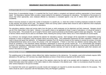
Key DrawingRolling Service Door with parts.Right hand door is illustrated. In a left hand door the barrel and both brackets are reversed. Guides for masonry jambs shown.HeadplateBracketBarrel AssemblyTENSION elDrive GearChain HoistHeadplateBracketAngle Guide(Assembly Shown)SafetyLabelDRIVE ENDSlide BoltDOLUBNOTRICAGUIDESTE604729-000110/22/92Step Lift HandleGuideLabelBottom BarFigure 1Angle Guide(Assembly Shown)Step Lift HandleSlide BoltPlease note that components and component locations are shown here for REFERENCE ONLY. Your unitinstallation and component locations may be different. 2015Overhead Door Corporation220153-00049/18/153
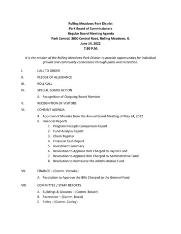
OperationFOR R E FE R E NCEDR IVE ENDDoor 4"6"10"Push UpReduced ChainDriveOperatorOPENING WIDTH GFEFigure 2DCOpeningHeightBHJAOverUp To*Excess shaft may be cut off of non-drive sides of doorsfor additional clearance. It is recommended that at least1” of shaft be retained past the headplate to facilitatespring tension adjustment.**Dimension “F” applies to Drive End only.RH shown, LH opposite.Head Plate HeightHRecommendedAxle SettingJMinimumRecommendedBack RoomAMinimumRecommendedMinimum-7' 8"10"8"9 1/8"Same18 1/8"Same7' 9"9' 4"10 1/2"8 1/2"9 1/8"Same18 3/8"Same9' 5"11' 0"11"10"10 1/4"Same19 3/4"Same11' 1"12' 8"11 1/2"10 1/2"10 1/4"Same20 1/4"Same12' 9"14' 3"12"11"10 1/2"Same20 1/2"Same14' 4"16' 0"13"12"10 1/2"Same21"SameFigure 3NOTE: Bracing may be required to prevent light weight buildingjambs from twisting.INSTALLATION1. Locate headplates per dimensions F, (or approximately 5”above top of guide, if headroom allows) E, H and G (Figure 1).2. Hold headplates in mounting position. Using a water level,check to make sure tops of headplates are level. Markmounting hole locations on header. See Table 1 for suppliedfasteners. Thru-bolts are recommended for brick or stonewalls or hollow Concrete Masonry Unit (CMU) wall. DO NOTinstall fastener in a void in the wall. If this condition existsthen use Thru-bolt. Fasten headplates to wall using threefasteners. Use top hole in headplates.3. IF DOOR IS CHAIN DRIVEN: (See page 9 for illustration)A. Slide 6:1 chain hoist onto door shaft. (Page 7)B. Align small gear of chain hoist with large ringgear mounted to curtain assembly.C. Secure two chain hoist bolts onto door shaft.D. Thread hand chain thru chain guide slots, overchain wheel and connect ends.NOTE: Make sure chain is not twisted.Head RoomBOpeningHeightOverUp ToRecommendedMinimum-7' 8"20 1/4"18 1/4"7' 9"9' 4"21"19"9' 5"11' 0"21 3/4"20 3/4"11' 1"12' 8"22 3/4"21 3/4"12' 9"14' 3"23 1/4"22 1/4"14' 4"16' 0"24 3/4"23 3/4"Table 1 - Headplate FastenersDoorsFastenerDrillSizeSteelAll3/8" bolt7/16“Concrete/MasonryAll3/8“ exp.anchor3/8“*WoodAll3/8“ Lag5/16“JambFastenerSpecificationsUse ANSI B95.12carbide tippeddrill bit*Drill size for supplied fasteners. For others, refer tomanufacturer’s specified installation method.See Page 4 For illustration4220153-00049/18/15 2015Overhead Door Corporation
4. Curtain assembly counterbalanceTable 2 - Guide Fastenerssprings will have to be wound duringJambDoorsWidthFastenerSpacingthe installment procedure. It is780CD Up to 16’1/4“ ScrewEvery other holeessential that the curtain bottom barSteelbe positioned correctly when placing790CW Up to 20’1/4“ ScrewEvery holecurtain assembly on headplates. A1/4“ Masonry Screwreference point marked on the curtain(3/16“ Drill Size,2-1/4” Deep)*ring and door shaft is required to780CD Up to 16’Every other holeneutralize the spring before clampingOptional 1/4“Concrete/the door shaft. See Table 3, Page 9, forExpansion AnchorMasonry(1/4“ Drill Size)for the initial turns required to windcounterbalance springs, then locateUp to 16’ 3/8“ Expansion AnchorEvery holebottom bar accordingly. (NOTE:790CWOverEvery holeIncorrect number of turns will affect16’ to 20’ 1/2“ Expansion Anchordoor operation. See directions on780CD Up to 16’1/4“ Lag ScrewEvery other holesheet 7 for adjusting spring tension.Upto16’3/8“LagScrewEvery holeEXAMPLE: If the number of initialWoodturns is 1 and ½, locate bottom bar at790CWOver1/2“ Lag ScrewEvery holethe ½ turn position (Figure 4). Step 816’ to 20’will explain the winding procedure.*Use ANSI B95.12 carbide tipped drill bit and drill sizes for supplied fasteners.5. Position curtain assembly onFor all others, refer to manufacturer’s supplied installation method.headplates according to dimension Jin Figure 3. Curtain must be centered on door opening.6. Install saddle clamps at both ends of door shaft as shown in Figure 5and securely tighten saddle clamps to headplates.7. Position guides to opening as shown in Figure 6. Clearance between1/2 TURNcurtain and inside of guides is shown in Figure 7. Adjust curtain orguides as necessary to achieve this spacing. Secure guides to jambswith supplied fasteners. See Table 2.CLOSEDIRECTION8. Curtain assembly counterbalance springs must now be wound for thenumber of initial turns required to set spring tension. As explained in3/4 TURN1/4 TURNStep 4, use the initial turn setting to wind counterbalance springs.EXAMPLE: If initial turn setting is 1 and ½ use the followingprocedures:NOTE DIRECTIONA. Starting at the ½ turn position, rotate curtain assembly on doorOF ARROWS ONshaft 1 and ½ turns in the “CLOSE” direction (See Figure 4).SADDLE CLAMPSFULL TURNB. Bottom bar should stop at the FULL TURN position.9. Secure bottom bar or hand chain to prevent curtain from unwindingFigure 4and remove retaining bands.10. Lower bottom bar into guide openings and lower curtain to thefloor.11. Install bottom bar stops as shown in Figure 8. Make certain the head7of the bolt is on the inside of the guides for proper door operation.12. Check both guides to insure the clearance shown in Figure 7 ismaintained along the full length of the guides. Adjust both guides6for clearance if necessary and secure.13. Make sure radius at top of guides leads curtain into guides smoothly.If necessary, bend radius to adjust.NOTE4DO NOT LUBRICATE GUIDES.DOOR SHOULD OPEN AND CLOSE WITH EQUAL EFFORT.If door is easy to close but hard to openINCREASE SPRING TENSIONIf door is easy to open but hard to closeDECREASE SPRING TENSION1689WARNINGExcessive Spring Tension can result in damage to the bottom bar and doorstop and if used while in such a damaged state can cause serious injury. 2015Overhead Door CorporationFigure 5220153-00049/18/155
TO ADJUST SPRING TENSION:Figure 613. (continued)A. Raise curtain to fully OPEN position.B. Loosen set screw on chain hoist, if present.C. Adjust spring tension (Figure 9) according to thefollowing procedure:AA. Apply torque to door shaft using a pipe wrench.1/4" 1/4"BB. Loosen saddle clamp bolt nuts at both ends of thedoor shaft.1/8"CC. Adjust spring tension as desired.toNOTE: DO NOT adjust more than ¼ turn at any time.3/8"DD. Tighten saddle clamp bolt nuts at both ends ofdoor shaft.D. Tighten set screw on chain hoist, if present.E. Check door operation. Readjust spring tension ifnecessary.14. Install slide locks to bottom bar as shown in Figure 10.NOTE: Distances are measuredFigure 7from the inside of the guide.IncreaseTension3/8" to 5/8"DecreaseTension1020231112Figure 8Figure 9Figure 10Figure 12Figure 11Jamb Type 780CD6220153-0004521790CWMasonryAll SizesWoodAll SizesSteelAll Sizes Up to 15’9/18/15Jamb Type790CWMasonryAll SizesWoodAll SizesSteelOver 15’ 2015Overhead Door Corporation
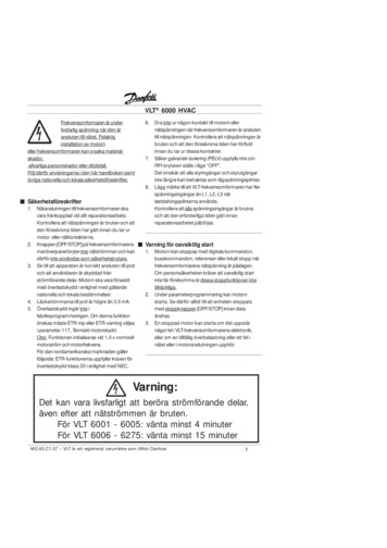
0110/22/926(k)3(k)9(k)Figure 13See page 8 for Bill of Materials(Callouts with (k) refer to the 6:1 CHAIN HOIST KIT Bill of Material) 2015Overhead Door Corporation220153-00049/18/157
STANDARD DOOR HARDWAREITEM PART NUMBERPART DESCRIPTION1202023-0002BRACKET, HEADPLATE2220154-0002STOP, BOTTOM BAR, RH3220154-0001STOP, BOTTOM BAR, LH4202157-0001SADDLE CLAMP, SHAFT5306973-0002SLIDEBOLT, 1" wide x 11-1/4" long6080302-2832WSHR, FLAT, PLD, 3/8" x 1" OD7080105-0628BOLT, HH, NC, 3/8" x 3-1/2" LG8080322-0382WASHER, LOCK, 3/8"9080352-0616NUT, HEX, PLD, 3/8-16 NCBOLT, CARRIAGE, SQ NECK, RND HD10 086420-05055/16" x 5/8"11 080302-2222WSHR, FLAT, PLD, 5/16" x 11/16" OD12 080352-0518NUT, HEX, PLD, 5/16-18 NC20 086480-1620NUT, HEX, W/LK WSHR, 1/4-2021 061239-0000SPACER, ROLLED, 1/4" x 1/4"BOLT, CARRIAGE, SQ NECK, RND HD23 086420-04081/4" x 1"24 205938-0001STEP / LIFT 04308579-0001604729-0001606853- 00 I 5-0001220207-0001220206-0001220153-00049/18/156:1 CHAIN HOIST KITKIT, FSTNR, WALL, STLKIT, FSTNR, WALL, STLKIT, FSTNR, HDW, COMLROPE, POLY, BULK, #8, 1/4"DIASTEP LIFT HANDLEINS, INSTL, COML, SHTDR, NO BRANDWARNING, LABEL, ROLLING DOORSDECALBOXBRKT, HDPL, .120" THKSLIDEBOLT, 1" W x 1-1/14" L, DADESTOP, BOTTOM BAR, SHTDR, LHSTOP, BOTTOM BAR, SHTDR, RH6:1 CHAIN Table 315' 6" up to 16' 5"14' 6" up to 15' 5"13' 6" up to 14' 5"12' 6" up to 13' 5"11' 6" up to 12' 5"10' 6" up to 11' 5"9' 6" up to 10' 5"8' 6" up to 9' 5"6' 6" up to 7' 5"5' 6" up to 6' 5"4' 6" up to 5' 5"3' 6" up to 4' 5"2' 6" up to 3' 5" 002.00Overhead Door Corporation
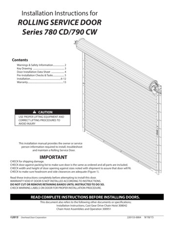
2413Figure 14ITEM1234 2015PART Overhead Door CorporationPART DESCRIPTIONJAMB EXTENSION - IDLE ENDJAMB EXTENSION - DRIVE ENDMOUNTING BRKT., .188 THK, LHMOUNTING BRKT., .188 THK, RHQTY1111220153-00049/18/159
STEP 17PRODUCT SAFETY INSTRUCTIONSThe door installer has the following responsibilities: Find labels in hardware box. Attach "Warning" Label 308579-0001, FIGURE 16, at a readable height on door drive sideguide or jamb. Attach "Do Not Lubricate" Label 604729 to wall at eye level, Figure 15. Demonstrate to the door user the correct way to control the closing speed of the rollingdoor with crank, hand chain or push-up operation; show that two hands should be usedto control the hand chain. Inform the door user about the following requirements from ANSI Z535.4: "Productsafety labels should be periodically inspected and cleaned by the product user asnecessary to maintain good legibility." The product user should order replacementsafety labels from the door manufacturer as required to maintain legibility. Inform the door user that electric operators must be installed on the door in accordancewith the instructions from the manufacturer of the operator.STEP 18 Attach chain keeper to wall or door guide assembly. Instruct door users to wrap handchain as shown in Figure 17. Tie rope to bottom bar.DO NOTLUBRICATEGUIDESWARNINGMOVING door couldresult in death orserious injury.Do NOT close dooruntil doorway is clear.SAFETY INSTRUCTIONS1. Control the speed of the doorduring manual operation.2. Do not stand or walk undermoving door.3. Keep doorway clear and in fullview while operating door.4. Do NOT permit children to playon, near, or with door or tooperate controls.5. Unlock door before openingdoor.6. Sensing devices on motoroperated doors should be testedfrequently.7. Adjustments or repairs must bemade by a trained door systemstechnician using proper tools andinstructions.8. Visually inspect door andhardware monthly for wornand/or broken parts and check tosee if door operates freely. DONOT operate a door with abroken spring.Place label at a readable heighton door drive side guide or jamb.Do NOT remove, cover, or paintover label.Figure 17604729-0001Figure 1510/22/92This label should be inspectedperiodically for legibility, and areplacement label should beordered form the door manufacturer as needed.08/27/2015308579-0001Figure 1610 220153-00049/18/15 2015Overhead Door Corporation
TroubleshootingSYMPTOMPOSSIBLE CAUSE1. Door is easy to close, but hard toopen.- Insufficient spring tension.\2. Door is easy to open, but hard toclose.- Excessive spring tension.3. Door is hard to operate.-4. Bottom weatherseal does not contactfloor evenly.-5. Door telescopes or rolls up unevenly.- Mounting brackets are not level, or are too low.- To straighten door curtain:A. Adjust mounting brackets to the correct position (Figures 1 &2).B. While positively retaining door curtain to prevent unwinding ofspring, remove guides from jambs.C. Lower curtain to floor, and carefully raise, to square the curtainback up on the barrel. (DO NOT remove positive hold on curtainuntil guides are back in place). Repeat as necessary.D. Replace guides and bottom bar stops.6. Door operates stiffly or curtain rattlesover guide leads.- Guides are too long.- Door assembly is mounted too far from opening.A. Adjustment must be made with door fully open.B. Loosen saddle clamp bolts on one end.C. Push curtain assembly toward header until correct setting hasbeen obtained. See dimension “J” - Figure 2 - Page 4.D. Retighten saddle clamp bolts.E. Repeat procedure for other end of curtain. Assembly MUST BEparallel with header.- Add shim behind top guide attachment to wall.- Mounting brackets to low:A. Raise brackets, orB. Cut track from bottom. (Door will hang in opening). 2015Overhead Door CorporationMounting brackets are not level.Curtain assembly is not parallel to opening.Door assembly incorrect distance from wall.Guide leads are improperly adjusted. (Adjustment must be madewith door fully closed).- Guides may be damaged.- Insufficient clearance between curtain and inside of guide. (CheckFigure 7 for required clearance on both sides).- Mounting brackets too low. Check Figures 1 & 2 for properlocation.Floor is not level.Mounting brackets are not level.Guides are not plumb.Spring tension too high. See Page 6, Figure 7 for tensionAdjustment procedures.220153-00049/18/1511
OPTIONAL HEADER SEAL1.2.3.4.With door closed, mark attachment point for header seal on curtain (Figure 18).Raise curtain until attachment point is accessible holes for rivets on 12“ centersusing a number 29 drill.Hold header seal along attachment point and drill.Secure header seal to curtain using 1/8“ diameter, large flange rivets.DOOR MOUNTED RUBBER SEALFigure 18HEADER MOUNTED RUBBER SEALFigure 19HEADER MOUNTED BRUSH SEALFigure 2012 220153-00049/18/15 2015Overhead Door Corporation
770-SS, 780-CD 790-CWRoll-Up Sheet DoorLimited WarrantyOverhead Door Corporation ("Seller") warrants to the original purchaser of the Series 790-CW, 780-CD or 770-SS RollingSheet door identified below (the “Product”), subject to all of the terms and conditions hereof, that the Product and allcomponents thereof will be free from defects in materials and workmanship under normal use for the following period(s),measured from the date of installation:xONE (1) YEAR ON ALL PARTS AND COMPONENTSSeller’s obligation under this warranty is specifically limited to repairing or replacing, at its option, any part which isdetermined by Seller to be defective during the applicable warranty period. Repair or replacement labor for any defectiveProduct part or component is included for a period of one (1) year from the date of installation. After that, any laborcharges are excluded and will be the responsibility of the purchaser.This warranty is made to the original purchaser of the Product only, and is not transferable or assignable. This warrantydoes not apply to any unauthorized alteration or repair of the Product, or to any Product or component which has beendamaged or deteriorated due to misuse, neglect, accident, failure to provide necessary maintenance, normal wear andtear, or acts of God or any other cause beyond the reasonable control of Seller.This warranty does not apply to any damage or deterioration caused by exposure to salt water, chemical fumes or othercorrosive or aggressive environments, whether naturally occurring or man-made, including, but not limited to,environments with a high degree of humidity, sand, dirt or grease. This warranty specifically excludes any damageresulting from scratching, abrasion or impact by any hard object, and any fading or color change which may not beuniform due to unequal exposure of the curtains to sunlight or other elements. Wearing away of the painted surfaces ofthe Product is a common occurrence resulting from the curtain repeatedly coiling upon itself and uncoiling during normalusage (See DASMA #274), and is specifically excluded from this warranty.THIS WARRANTY IS EXCLUSIVE AND IN LIEU OF ANY OTHER WARRANTIES, EITHER EXPRESS OR IMPLIED,INCLUDING BUT NOT LIMITED TO ANY IMPLIED WARRANTY OF MERCHANTABILITY OR FITNESS FOR APARTICULAR PURPOSE.IN NO EVENT SHALL SELLER BE RESPONSIBLE FOR, OR LIABLE TO ANYONE FOR, SPECIAL, INDIRECT,COLLATERAL, PUNITIVE, INCIDENTAL OR CONSEQUENTIAL DAMAGES, even if Seller has been advised of thepossibility of such damages. Such excluded damages include, but are not limited to, loss of goodwill, loss of profits, lossof use, cost of any substitute product, interruption of business, or other similar indirect financial loss.Claims under this warranty must be made promptly after discovery, within the applicable warranty period, and in writing tothe Seller or to the authorized distributor or installer whose name and address appear below. The purchaser must allowSeller a reasonable opportunity to inspect any Product claimed to be defective prior to removal or any alteration of itscondition. Proof of the purchase and/or installation date, and identification as the original purchaser, may be required.ORIGINAL PURCHASER:INSTALLATION ADDRESS:SELLER:SELLER’S ADDRESS:FACTORY ORDER #:DATE OF INSTALLATION:SIGNATURE OF SELLER:
14 220153-00049/18/15 2015Overhead Door Corporation
2015 Overhead Door Corporation 220153-0004 9/18/15 3 Figure 1 Key Drawing Rolling Service Door with parts. Right hand door is illustrated. In a left hand door the barrel and both brackets are reversed. Guides for masonry jambs shown. Please note that components and component locations are shown here for REFERENCE ONLY. Your unit