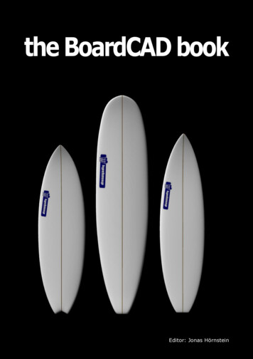
Transcription
the BoardCAD bookEditor: Jonas Hörnstein
Version 1.0, January 2011
TABLEOF CONTENTS1. Introduction.052. Quick tutorial.073. Setting preferences.154. Using templates.215. Bezier editing.256. Nurbs editing.317. Scaling. 378. Printing. 419. Exporting models.4310. Generating and exporting g-code.4711. Scanning boards.51
1. INTRODUCTIONBoardCAD is an open source CAD/CAM-system forsurfboards. It is aimed at facilitating the design process andto stimulate creativity by allowing the shaper to play withdifferent parameters in the design. The result can beimmediatly visualized in 3D, giving important feedback tothe shaper. BoardCAD also allows the shaper to print fullscale templates or even send the design to a CNC-machineto have it produced and taken for a ride. While it is only inthe water that it is possible to validate a design, knowingexactly what has been changed between different boardsallows the shaper to learn much more from each of them.BoardCAD doesn't automatically make you into a goodshaper, but used in the right way it can help you both tolearn faster and to become more productive.This book is both a guide on how to use BoardCAD, and adetailed reference for its funcionality. It is suggested thatyou first read the quick tutorial in chapter two to get afeeling for the overall workflow and the functionality offeredby BoardCAD. The following chapters focus on more specifictopics and can be read in any order. For information on howto get and install BoardCAD, and for more generalinformation about the project, we refer to the project'shomepage http://www.boardcad.com and our wiki athttp://www.boardcad.org.
2. QUICKTUTORIALThis chapter provides an overview of the most importantfunctionality and the workflow for designing a board, fromdefining the basic outline and rocker, to generating and finetuning a complete 3D-model.2.1 Creating or opening a boardNormally you don't create a board from scratch, but start byopening one of your existing models. From version 2.0,BoardCAD mainly works with STEP-files (.stp), but it can stillread and save files in the previous formats (.brd and .cad).Apart from these native formats, BoardCAD can read filesfrom aps3000, shape3D, surfcad and akushaper.If it's the first time you use BoardCAD it is natural that youdon't have any existing models to start from. ThereforeBoardCAD comes with three basic shapes (funboard,shortboard, and longboard) that can serve as a startingpoints. You can find them by chosing new in the file menu.For this tutorial we choose the shortboard. This creates 2Ddrawings of the outline, rocker, and a number of crosssections along the board.2.2 Editing the curvesThe first thing we want to do is to scale the board to thedesired size. If you, like most shapers, have your headsetup to work with feet and inches, you should make surethat BoardCAD does the same in order to avoid having toconvert all your measures to mm. This can be done from thedrop down list named unit. For this tutorial we chooseImperial (decimal) as our unit. Now we can comfortably clickthe scale button and type in our desired measures, e.g.5'10" x 20" x 2.25". There is a lot more that can be saidabout scaling, but that's a chapter in its own, and for now
we don't need to care about all the details.Now we are ready to start editing our curves. Let's startwith the outline. There are lots of tricks you can use tofacilitate the design, like using another board model orimage of a board as a template. By having them shown inthe background it is easy to trace their outline when editingthe curves. This will be shown in chapter 4, but here we doour outline without any aid.The outline is defined as a Bezier curve which is made up ofa number of segments. Each segment starts at a bluecontrol point and ends at the next blue control point.Between those two blue points there is a red and a yellowpoint. These define the form of the curve within the specificsegment. You can control the shape of the outline by simplyclicking and dragging the control points. To force thetangent of the curve to be continuous between twosegments, you can click on the blue control point betweenthem and mark "continuous".
If needed you can also add or remove control points. Whilemore control points give more freedom in design it alsomake it harder to create smooth lines, so only add guidepoints when strictly necessary. Details on how to work withthe control points are given in chapter 5.Next we define the rocker by clicking on profile. There isone Bezier curve for the deck and one for the bottom. Youcan switch between them by clicking the "ToggleDeck/Bottom" icon. For the deck it is good practise to followthe rocker of the blank when possible. Again we refer tochapter 4 for details on how to show a blank model in thebackground, or chapter 11 for instruction on how to scan ablank using a CNC machine. Here, we use our artisticfreedom to define the rocker. Just as for the outline, we canedit our curves by clicking and dragging the control points.It is possible to select several control points and move themat the same time, which is especially useful for changing therocker in the tail and nose while maintaining the samethickness.
Finally we define our cross sections. The cross sections areresponsible for the form of the rails, and how all the linesflow in 3D. To ensure a good flow it is advisable to use fewcross sections. One trick is to start with only one crosssection in the center of the board and edit that to thedesired form. Next you add cross section for example at 1foot from the tail and 1 foot from the nose. These crosssections will now be copies of the cross section at the centerof the board and it is easy to control how you want the flowof rail to change towards the tail and towards the nose.Typically you'll want a harder rail and less tucked undertowards the tail, and a higher rail with more tucked under inthe nose. It may also be necessary to define extra crosssections for the last few inches of the board. By doing thisafter we have edited the cross sections at one foot off thetail and nose, we again make it easy to change the railwithout breaking the flow.
2.3 Creating a 3D modelNow the main design of the board is already done, and if wewant to print 2D templates (as described in chapter 8) wecan actually do that directly without creating a 3D model. Onthe other hand, if we want to use the model in another CADsystem, or have it shaped in a CNC machine, we cannot dothat without a 3D model. In any case, at this point you areprobably eager to see what your board looks like in 3D, sowe simply create a 3D-model by chosing "Approximate fromBezier" in the 3D-menu. As the name suggests, the 3Dmodel only approximates the 2D curves. The reason for thatis that we want a 3D model that can easilty be modeledfurther in order to achieve things such as swallows tails, thatcannot be modelled in 2D. The standard 3D model is able toapproximate most board shapes quite accurately. However, itis possible to increase the resolution of the 3D-model or editthe position of its control points in order to improve theapproximation when necessary, see chapter 6 for details.
In version 2 of BoardCAD, the 3D-model is shown directly inthe same window as the Bezier curves. This makes it easysee how well the curves were approximated. While the 3Dmodel shown in these windows gives a good idea of how theboard looks, an even better visualization is available in theredered view. To render the board choose "Render nurbsmodel" from the Render menu.Now let us do some editing and create a one inch swallowtail. First we move the segment placed at 20 mm from thetail forward so that it does not get affected by the swallowtail. To move a segment forwared we first have to uncheck"x-locked" from the popup menu that appears when you doa right-click on the mouse. Now we can click on the outlinepoint and drag it forward. Note that since the points aredefined in 3D-space, all views are affected and even therocker is changed by moving the segment forward. We canadjust the rocker either by hand or by reapproximating the3D-model.Next we adjust the tail segment to the desired width, andselect "Tail designer" from the 3D menu to set the depth ofthe swallow tail. The 3D model always works with mm, so
we type in 25. The result is a retro-looking swallow. We canfine adjust the tail by selecting "Advanced editing" in the 3Dmenu and move the individual points.2.4 Saving the boardFinally we save our model. As already stated, BoardCADversion 2.0 has a new STEP-based file format. To save theboard as a STEP-file, select "Save As" and name the fileusing .stp as the file extension. Using this format both the2D Bezier curves and the final 3D-model are saved in onesingle file. Before version 2.0, the 2D model was saved using.brd-format, and the 3D model using .cad as file extensions.For backward compatibility these formats are still available.It is also possible to export the board model using a numberof standard CAD-formats. More information about these canbe found in chapter 9.
3. SETTINGPREFERENCESBoardCAD is intended to be used by anyone who isinterested in designing surfboards, from the backyardshaper to the full-time professional. Of course, differentusers have different needs and preferences. BoardCAD istherefore highly configurable and it is possible to controlboth the visual apperance of the board models and whatkind of design aids you'd like to be present on the screen. Itis also possible to select a different language for the menus.3.1 Viewing design aidsUnder the View-menu you'll find a list of different designaids that can be switched on and off. While all are useful,having all shown at the same time tend to clutter theworkspace and make it more difficult to edit the board. Mostof the design aids are self-explanatory, but below you willfind a short description on each of them.- Shows a grid in the background. Depending onwhether the unit is set to metrics or imperial, the distancebetween each grid-line is set to 1 cm or 1 inch respectively.- Shows the curves of another board in thebackground, given that a ghost board has been loaded.More details on ghost boards are available in chapter 4.- Shows the curves of the current boardbefore they were edited.- Show the control points that allows thecurve to be edited. By hiding these no editing can be doneto the curve. This can be useful when editing the surfacemodel in order to avoid that the bezier curves get moved bymistake.
- Showsimultaneously in the cross section view.allcrosssection- Guide points are explained in chapter 4.- The curvature is a measure of how far fromflat a curve is. For a flat line the curvature is equal to zero,and for other curves the curvature is equal to the inverse ofits radius at every point. This means that if the curvature ofthe rocker is equal to zero, the rocker is totally flat at thatpoint, and if it goes below zero it means that the board hasnegative rocker.- Shows much volume each part ofthe board has.- This shows the volume center- The sliding info gives information about thewidth and thickness of the board at the point where themouse is placed.- Shows the cross section at thepoint where the mouse is placed.- Shows fin position- Shows a background image if suchimage is loaded. More info on backgroud images can befound in chapter 4.- Using anti-aliasing smoothens the jaggedlines that occurs due to the low resolution of computerscreens.- Shows a zero-line under the board- Shows the distance overthe bottom tail, from the tail and the nose, to the currentmouse position.- Shows where the cross sectionsare placed.- Shows the flow of the rail at 30, 45, 60, and
90 degrees- Shows the tucked under- Shows rocker and width of board at tail,nose, center, one-foot-off and two-foot-off.3.2 Setting visual appearanceBy choosing Misc, Settings, in the menu you get a dialogwindow where it is possible to configurate the visualappearance of the board model and all the design aidsdescribed above. The dialog window has three tabs.- In the size and thickness you can controlthe size of the control points and the line thickness of theboard model.- A number of different configurations that didn't fitunder the other tabs. Look and feel lets you set theappearance of the GUI, in order to give BoardCAD either aplatform independent look and feel like Metal or a nativelook and feel that make BoardCAD look more like a nativeapplication and less java-like. Print guide points, and Printfins, configures whether those will be visible when printingboard information sheets or templates. The fractionaccuracy configures to what fraction of an inch thatmeasurements will be shown, when imperial units are used.Default value is 16, i.e. 1/16 of an inch. If Use Rocker StickAdjustment is turned on, the rocker will be adjusted so thecenter tangent is level. This is similar to the industrystandard way of measuring rocker with a rocker stick. Offsetinterpolated cross sections by rocker means that the crosssections will be drawn in their full 3D-position rather thanflat. This is especially useful when comparing the rail of the3D-model with the rail of drawn in the 2D-view.- Let you set the color of the board model and thedifferent design aids.3.3 Choosing Bezier interpolationFinally it is possible to configure how the cross sections areinterpolated in the Bezier model. This affects how n
BoardCAD is an open source CAD/CAM-system for surfboards. It is aimed at facilitating the design process and to stimulate creativity by allowing the shaper to play with different parameters in the design. The result can be immediatly visualized in 3D, giving important feedback to the shaper. BoardCAD also allows the shaper to print full scale templates or even send the design to a CNC-machine .
