Transcription
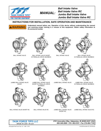
MANUAL:Ball Intake ValveBall Intake Valve RCJumbo Ball Intake ValveJumbo Ball Intake Valve RCINSTRUCTIONS FOR INSTALLATION, SAFE OPERATION AND MAINTENANCEWARNINGUnderstand manual before use. Operation of this device without understanding the manualand receiving proper training is a misuse of this equipment. Obtain safety information attft.com/serial-numberBALL INTAKE VALVEBALL INTAKE VALVE SHORTW/ PARALLEL DRIVE GEARBOXBALL INTAKE VALVEBALL INTAKE VALVEW/ PARALLEL DRIVE GEARBOXJUMBO BALL INTAKE VALVESHORTJUMBO BALL INTAKE VALVESHORT W/ PARALLEL DRIVEGEARBOXJUMBO BALL INTAKE VALVEJUMBO BALL INTAKE VALVEW/ PARALLEL DRIVE GEARBOXBALL INTAKE VALVE SHORT RCBALL INTAKE VALVE RCJUMBO BALL INTAKE VALVESHORT RCJUMBO BALL INTAKE VALVE RCTASK FORCE TIPS LLCMADE IN USA tft.com Copyright Task Force Tips, LLC 2002 - 20183701 Innovation Way, Valparaiso, IN 46383-9327 USA800-348-2686 219- 462-6161 Fax 219-464-7155LIA-200 November 20, 2018 Rev20
Table Of Contents1.0 MEANING OF SIGNAL WORDS2.0 SAFETY3.0 GENERAL INFORMATION3.1 SPECIFICATIONS3.2 CORROSION3.3 USE WITH SALT WATER4.0 INSTALLATION4.1 MOUNTING ON TRUCK4.2 ENCLOSURE MOUNTING4.3 ELECTRICAL INSTALLATION AND WIRING4.4 ELECTRICAL TESTING4.5 CHANGING HANDWHEEL TO LEFT SIDE(NON RC MODELS)4.6 CHANGING HANDWHEEL TO LEFT SIDE(RC MODELS)4.7 BALL INTAKE VALVE RC MANUAL OVERRIDE4.8 CHANGING OFFSET OF CRANK HANDLE4.9 CHANGING COUPLING LOCKOUT4.10 STORZ ‘SUCTION GASKET’ REQUEST5.0 USE5.1 INTAKE ELBOW5.2 VALVE OPERATION5.3 RC VALVE OPERATION5.4 AIR VENT AND WATER DRAIN5.5 PRESSURE RELIEF VALVE5.5.1 RELIEF VALVE SETTING PRESSURE5.6 SUCTION SCREEN5.7 PRESSURE LOSS6.0 EXPLODED VIEWS AND PARTS LISTS6.1 BALL INTAKE VALVE AB & AC SERIES EXPLODEDVIEW AND PARTS LIST6.2 JUMBO BALL INTAKE AP, AQ, AX & AZ SERIESEXPLODED VIEW AND PARTS LIST6.3 MOTOR ASSEMBLY BIV RC & JUMBO BIV RCEXPLODED VIEW AND PARTS LIST6.4 SIDE B OUTLET OPTIONS EXPLODED VIEWSAND PARTS LISTS6.5 PARALLEL DRIVE GEARBOX [A] EXPLODED VIEWAND PARTS LIST6.6 WORM DRIVE GEARBOX [B] EXPLODED VIEW ANDPARTS LIST6.7 AIR VENT/DRAIN [C] EXPLODED VIEW AND PARTSLIST7.0 TROUBLE SHOOTING8.0 WARRANTY9.0 MAINTENANCE9.1 SERVICE TESTING9.1.1 HYDRAULIC TEST9.1.2 RELIEF VALVE TEST9.1.3 SHUTOFF VALVE TEST9.1.4 RECORDS9.2 CRANKSHAFT OVERRIDE AND REPLACEMENT9.2.1 CRANKSHAFT OVERRIDE9.2.2 DIAGNOSIS9.2.3 CRANKSHAFT REPLACEMENT10.0 REPAIR11.0 ANSWERS TO YOUR QUESTIONS12.0 TEMPLATES13.0 INSPECTION CHECKLISTOPERATING RANGE:DANGERFor Ball Intake ValvesPressure Max 300 PSI (20 bar)PERSONAL RESPONSIBILITY CODEThe member companies of FEMSA that provide emergency responseequipment and services want responders to know and understand thefollowing:1. Firefighting and Emergency Response are inherently dangerous activitiesrequiring proper training in their hazards and the use of extreme cautionat all times.2. It is your responsibility to read and understand any user’s instructions,including purpose and limitations, provided with any piece of equipmentyou may be called upon to use.3. It is your responsibility to know that you have been properly trained inFirefighting and /or Emergency Response and in the use, precautions, andcare of any equipment you may be called upon to use.4. It is your responsibility to be in proper physical condition and to maintainthe personal skill level required to operate any equipment you may becalled upon to use.5. It is your responsibility to know that your equipment is in operablecondition and has been maintained in accordance with the manufacturer’sinstructions.6. Failure to follow these guidelines may result in death, burns or othersevere injury.For Jumbo Ball Intake ValvesPressure Max 250 PSI (17 bar)Pressure Min Full Vac.Hydrostatic Proof Test:900 PSI (62 bar)per NFPA 1965Six seconds from open to closemeets NFPA 1901slow close requirement. Copyright Task Force Tips, LLC 2002 - 2018FEMSA2Fire and Emergency Manufacturers and Service AssociationP.O. Box 147, Lynnfield, MA 01940 www.FEMSA.orgLIA-200 November 20, 2018 Rev20
1.0 MEANING OF SIGNAL WORDSA safety related message is identified by a safety alert symbol and a signal word to indicate the level of risk involved with a particularhazard. Per ANSI standard Z535.6-2006, the definitions of the four signal words are as follows:DANGERWARNINGCAUTIONNOTICEDANGER indicates a hazardous situation which, if not avoided, will result in death or seriousinjury.WARNING indicates a hazardous situation which, if not avoided, could result in death or seriousinjury.CAUTION indicates a potentially hazardous situation which, if not avoided, may result in minoror moderate injury.NOTICE is used to address practices not related to personal injury.2.0 SAFETYWARNINGDo not use AC current to operate the Ball Intake Valve RC or the Jumbo Ball Intake Valve RC. TheBall Intake Valve RC and the Jumbo Ball Intake Valve RC are 12 or 24VDC systems ONLY! Usingthe wrong power source could cause electrocution, resulting in death or serious injury.WARNINGInjury or death can result from burst hoses and fittings. Risk can be minimized by the proper careand use of hose and appliances per NFPA 1962. The relief valve must be set to an appropriatepressure based on the type of hose and equipment you are using.WARNINGInjury or death may occur by attempting to use a damaged Ball Intake Valve. Before using thevalve inspect it for damage resulting from: Failure to drain valve followed by exposure to freezing conditions Exposure to temperatures in excess of 160 degrees F Missing parts, physical abuseWARNINGThis equipment is intended for use by trained personnel for firefighting. Its use for otherpurposes may involve hazards not addressed by this manual. See appropriate guidance andtraining to reduce risk of injury.WARNINGKinks in supply hose may reduce water flow and cause injury or death to persons dependant onwater flow. When this valve is used on a hydrant or fire truck it is recommended that it be usedwith an elbow to minimize risk of hoseline kinks.CAUTIONThe electric Ball Intake Valve RC and the Jumbo Ball Intake Valve RC may be remotely operated.The electric drives are current limited but may still produce enough force to cause injury. Keephands and fingers away from pinch points on the valve.CAUTIONCAUTIONCAUTIONDo not use the manual override hand wheel while the electric controls are in operation. Theelectric drives produce enough torque to cause injury.The Ball Intake Valve RC and the Jumbo Ball Intake Valve RC have current limiting capabilitieswhich stops the motor if an obstruction is encountered. The Ball Intake Valve RC and the JumboBall Intake Valve RC must be installed as instructed using the correct controls and electricalboxes. Failure to do so will result in damage to the electric motor and loss of current limitingcontrols. This may result in injury.Maximum operating pressure for the Ball Intake Valve models 300 PSI (20 bar). Do not exceed300 PSI on either side of the Ball Intake Valve. Maximum operating pressure for Jumbo BallIntake Valve models 250 PSI (17 bar). Do not exceed 250 PSI on either side of the Jumbo BallIntake Valve.CAUTIONValve must be properly connected. Mismatched or damaged connectors may cause leaking oruncoupling under pressure and could cause injury.CAUTIONThe Ball Intake Valve may become damaged if it is allowed to freeze while containing water.Always drain after use to avoid damage and possible loss of use.NOTICEUse with salt water is permissible provided the valve is thoroughly cleaned with fresh water aftereach use. The service life of the valve may be shortened due to the effects of corrosion and isnot covered under warranty. Copyright Task Force Tips, LLC 2002 - 20183LIA-200 November 20, 2018 Rev20
3.0 GENERAL INFORMATIONNOTICEBall intake valves were initially designed as Large Diameter Hose intake valves. Ball Intake Valvesfunction as either a pressure (discharge) or vacuum (intake) valve for Large Diameter Hose. Themanual applies to both applications of Ball Intake Valves.The Ball Intake Valve and the Jumbo Ball Intake Valve are intended for use on the intake manifold of a fire engine. The valve is keptclosed while the water supply from a hydrant or another pumper to the engine is being established. This prevents the pump fromsucking air through the intake manifold and losing its prime. Once the supply hose is filled and under pressure, and the air has beenvented from the hose, the valve may be opened to connect the pump to the water supply. An adjustable pressure relief valve mountedon the bottom of the valve opens to relieve any excess pressure that may damage the hose or the pump.An electric remote controlled (RC) model allows the valve to be operated from a remote location. A typical installation will consistof the BIV RC and a remote display operator station. Motor controls are designed to auto sense 12 VDC or 24 VDC operation. Themotor control circuit utilizes a position encoder and current limiting to protect the drive train at the ends of travel. Unit is supplied with2’ of cable with a plug on BIV RC and 10’ of cable with a receptacle so installation effort is minimized. Cable has only four conductors(two for power and two for communications) further easing installation effort. To complete the installation, the installer will need tomount and wire the remote display operator station. The power supply for the BIV RC will need to be connected to a protected circuitfrom the trucks power distribution center. Refer to the specifications section 3.1 for nominal current draw.Valve Position IndicatorShot PinKnobValve Position IndicatorShot PinKnobHandwheelHandwheelOutletSide ACouplingOutletSide ACouplingIntakeElbowSwivelSide BCouplingAir Vent & DrainIntakeElbowSwivelSide BCouplingAir Vent& DrainPressure Relief ValveAB1ST-NXBall Intake Valve w/Pressure Relief ValveAC1ST-NXBall Intake ValveElectric MotorValve PointerLocationCrankAB1ST-NX-PSBall Intake Valve With Parallel Drive Gearbox Copyright Task Force Tips, LLC 2002 - 2018Manual OverrideHand WheelPLUGAB1ST-NX-RCBall Intake Valve RC4LIA-200 November 20, 2018 Rev20
3.1 SPECIFICATIONSMODELBALL INTAKEVALVEJUMBO INTAKEVALVEBALL INTAKE VALVERCJUMBO INTAKE VALVERCWaterway Size3.65” (93mm)5.25” (133mm)3.65” (93mm)5.25” (133mm)Max Pressure300 psi (20 bar)250 psi (17 bar)300 psi (20 bar)250 psi (17 bar)Min PressureFull VacuumFull VacuumFull VacuumFull VacuumOpening/Closing SpeedVoltage - Auto SenseMotor Current(RC Only)6 sec6 sec12 or 24volt DC12 or 24volt DCNominalLimit@ 12 VDC@ 24 VDC@ 12 VDC@ 24 VDC3 amp1.5 amp12 amp6 ampRecommended Fuse or Circuit Breaker Size15 amp@12 Volt7.5 amp @ 24 VoltTemperature Rating*-25 F to 135 F (-32 C to 57 C)*For temperatures below 32 F(0 C), valves must be drained after use to avoid damage. See section 2.0 SAFETY.Environmental RatingAll components designed to meet minimum rating of NEMA 4 (IP65)3.2 CORROSIONAluminum parts are hard anodized. All castings are then powder coated inside and out to help prevent corrosion. Hose couplings areattached using polymer bearing rings which provide electrical insulation to help prevent galvanic corrosion. The effects of corrosioncan be minimized by good maintenance practice. See section 9.0 MAINTENANCE.3.3 USE WITH SALT WATERUse with salt water is permissible provided valve is thoroughly cleaned with fresh water after each use. The service life of the valvemay be shortened due to the effects of corrosion and is not covered under warranty.4.0 INSTALLATION4.1 MOUNTING ON TRUCKScrew the large coupling to the pump inlet manifold. The valve position indicator should be clearly visible, but need not be level.4.2 ENCLOSURE MOUNTINGSelect proper location for display. A full size template is shown in section 12.0.4.3 ELECTRIC INSTALLATION AND WIRINGRed ( ) and black (-) wires must be connected to a 12 or 24 VDC protected circuit from the truck’s power distribution center. Figure4.3 shows the control WHITETYPICAL TERMINAL BOXCONNECTIONSBIV OPERATORSTATIONINTERFACE BOX(OPTIONAL)RECEPTACLEINSTALLER SUPPLIEDTERMINAL BOX OR OPTIONALINTERFACE BOX CAN BE USEDMULTIPLE OPERATOR STATIONS MAY BE INSTALLED. ALLCOMMUNICATION PAIRS (BLUE & WHITE) AND POWERPAIRS (RED & BLACK) MUST BE CONNECTED IN TERMINALBOX OR ANOTHER INTERFACE BOX.REDBLACKBALL INTAKE VALVEPLUG30 FT (9M) MAXIMUMELECTRIC MOTORMANUAL OVERRIDEHANDWHEELDUST CAPINSTALLERSUPPLIEDPOWER CABLEAB1ST-NX-RCBALL INTAKE VALVE RCNOTE:TO AVOID EXCESSIVE VOLTAGE DROP AT VALVE MOTOR, DO NOTLENGTHEN FACTORY SUPPLIED RECEPTACLE CABLE. POWER CABLESELECTION IS CRITICAL. VOLTAGE SUPPLIED TO VALVE MOTOR BOARDSHOULD NOT FALL BELOW 10 VOLTS WHEN VALVE IS IN OPERATION.NOTE:CABLE IS GEL FILLED TO PREVENT MOISTURE WICKING INTOENCLOSURE. GEL IS NON-HAZARDOUS AND SHOULD BEWIPED OFF CONDUCTORS WITH RAG.Figure 4.3WARNINGThe electric motor and other components are ignition sources. The electric BIV should be operated onlyin areas where there is adequate ventilation and no hazard of flammable vapor buildup. Copyright Task Force Tips, LLC 2002 - 20185LIA-200 November 20, 2018 Rev20
4.4 ELECTRICAL TESTINGVERIFY PROPER VOLTAGEThe TFT Ball Intake Valve RC has built in circuit protection to guard against a circumstance where the unit’s movement is blockedbefore reaching its full travel limits. Without this circuitry the motor would stall, overheat, and could be permanently damaged.IMPORTANT - When mechanical installation and electrical connections are complete, perform the following test to verify voltagesupply is adequate and the current limiting feature is functioning.1. Apply power to Valve Control.2. Press OPEN or CLOSE button and hold until valve reaches stop position. Continue to hold button down.3. Once movement is stopped, manually turn override knob in opposite direction while continuing to hold buttondown. If knob can be turned, then voltage supply is adequate. If knob can’t be turned and motor continuesto operate, then the current limit was not reached because the voltage supply or wiring is not adequate.NOTE: Override knob will only turn in one direction.To ensure proper voltage to the Ball Intake Valve RC, the wiring needs to be checked for proper gauge for the installed length ofwire, and for proper termination. Also, ensure that the power source supplying the BIV RC and the grounding are adequate (otherelectrical loads on a shared circuit with the BIV RC may cause a low-voltage situation).In addition to motor damage, a further consequence of low voltage could be that the valve will not open or close properly or fully.SET TRAVEL STOPSWhen proper voltage is verified, perform the following to set the full travel limits.1. Apply power to Valve Control.2. Press CLOSE button and continue to hold until valve is fully closed. Motor must stop by current limit method. If motor continuesto operate see proper voltage section above.3. Press OPEN button and continue to hold until valve is fully open. Motor must stop by current limit method. If motor continuesto operate see proper voltage section above.4. Position indicator lights will now track valve movement.4.5 CHANGING HANDWHEEL TO LEFT SIDE (NON RC SSEMBLYKEYThe handwheel is shipped from the factory on the right hand side of the valve. The hand wheel can be switched to the left hand sidefor convenience or if it interferes with other equipment on the pump panel.To move the handwheel to the opposite side, remove the retaining ring on the end of the shaft. Pull the shaft out of the gear box. Asthe shaft is withdrawn, grasp the small key on the shaft so it does not get lost. Remove and switch the two plastic bushings that comeout of the sides of the gearbox. The bushing with the large hole is installed on the same side as the handwheel.Look through the gear box and note approximate position of the keyway in the worm inside the gear box. Slide the shaft into thegearbox on the opposite side of the gear box with the key oriented the same as the keyway. A small dab of grease will keep the keyplace. Rotate the shaft until the key finds the keyway and push the shaft in until it stops. Reinstall the retaining ring. Do not overexpand the retaining ring. Copyright Task Force Tips, LLC 2002 - 20186LIA-200 November 20, 2018 Rev20
4.6 CHANGING HANDWHEEL TO LEFT SIDE (RC MODELS)STEP 1: Remove screws and end coverSTEP 2: Slide off both sprockets and chain as one unit.STEP 3: Remove button head screw and lock washer to remove motor unit.NOTE: Remove set screw that is in hole for the button head screw and reinstall the set screw on the other side.The set screw plugs the hole to keep dirt from entering the gearbox.STEP 4: Remove 4 screws and reposition motor so electric wire points in desired direction.STEP 5: Change hand wheel to other side as in Section 4.3.STEP 6: Reverse steps 1, 2 and 3 to reinstall motor on other side. Apply Blue Loc-Tite thread locking compound to all of the screwthreads.STEP 7: Reverse polarity (direction) of motor by holding OPEN and CLOSE buttons together for 15 seconds.STEP 4STEP 1STEP 2STEP 3STEP 54.7 BALL INTAKE VALVE RC MANUAL OVERRIDEThe Ball Intake Valve RC is motor driven but also has an override handwheel for operating the valve manually. The overridehandwheel may also be used in the event of power failure. If electrical power is supplied to the control panel then the LED valveposition display will track the valve’s position as the handwheel is moved. If the handwheel is moved while there is no power to theelectric controls than the LED valve position display will be in error when the electric power is reconnected. The LED valve positionindicator will self correct the first time the valve is cycled under electric control.If more compactness is desired the override handwheel may be removed. The drive shaft has a hex so a wrench or socket may beused for manual override. If the manual override handwheel is removed assure that the correct size wrench of socket is availablein the event of power failure.11/16” (18mm) Hex Copyright Task Force Tips, LLC 2002 - 20187LIA-200 November 20, 2018 Rev20
4.8 CHANGING OFFSET OF CRANK HANDLEWhen equipped with a crank handle, two offset positions are available to adjustthe swing radius of the crank and knob as shown. The longer offset positionoffers reduced effort to operate the valve. The shorter offset is available to avoidinterference with other equipment on the apparatus. To change the offset, removetwo 1/4”-20 x 1/2” button head cap screws from crank. Place crank in desiredposition and replace screws. Apply Blue Loc-Tite thread locking compound to allof the screw threads.LONGER OFFSET POSITION2.6" [67mm]SWING RADIUSSHORTER OFFSET POSITION1.6" [41mm]SWING RADIUS4.9 CHANGING COUPLING LOCK-OUTTo change a coupling from rigid to full time swivel, use a 7/32” Allen driver toback out the lockout screw until the coupling moves freely.To change a coupling from full time swivel to rigid, first align the pull pin in theelbow to vertical. Rotate the coupling until the lockout screw is aligned with thepull pin. Use a 7/32” Allen driver to tighten the lockout screw into the lockoutdivot in the elbow. Do not tighten the screw onto the polymer bearing strip.PULL PINLOCK-OUT SCREW4.10 STORZ ‘SUCTION GASKET’ REQUESTIf your application of this product requires drafting, you may need a suctiongasket, please call 1-800-348-2686 to receive a free suction gasket by mail.Part Numbers: 4” STORZ - item # A4216, 5” STORZ - item # A4221, 6” Storz- item # A42735.0 USE5.1 INTAKE ELBOW25 kg137 lb62 kg213455 lb41 N-m14CLOSED14134234OPEN216 N-m30 ft-lb112 ft-lb133 mm193 mm5.25 inCLOSED143.65 in14Max AcceptableTorque2Valve Seat BoreSize345.2 VALVE OPERATIONThe valves covered by this manual utilize positive stops at the OPEN and CLOSED positions.Attempting to close a valve further than the positive stops will not result in a tighter sealbetween the ball and valve seat. All valves include markings to indicate the direction of handlerotation to open the valve.Valves with hand cranks include a valve position indicator. To open the valve, turn the handcrank until the valve position indicator shows OPEN. To close the valve, turn the hand crankthe opposite way until the valve position indicator shows CLOSED.Up to the maximum rated pressure, operating torque should never exceed the values in thetable below. If greater torque is required to operate the valve, then that is an indication thatthe valve needs maintenance. Exceeding 30 ft-lb / 41 N-m torque may damage the appliance.Kicking or standing on the valve controls is considered misuse of the appliance.OPENThe intake elbow swivels 360 degrees to help prevent hose kinks, and make connection of suction lines easier. The intake can beturned forward or backward to help make connections in tight places if the water supply is in front of or behind the truck. To turn theelbow, pull the shot pin knob on top of the elbow. The elbow will lock into a detent every 45 degrees. There is a hole on the side ofthe elbow that can be used to attach the lanyard or chain of a cap by use of a key ring . The elbow may be swivelled to any of eightpositions by pulling the shot pin knob.Max. AcceptableForce on KnobFor valves with parallel shaft gearboxes, exceeding 30 ft-lb will result in permanent damage to several components in the gearbox.The damage may not be outwardly obvious, but could result in inability to operate the valve. To restore normal operation, the entiregearbox must be replaced after relieving pressure from the valve.For valves with worm drive gearboxes, exceeding 45 ft-lb will cause one side of the crank shaft to shear off. This is intentional toprevent further damage to the gearbox. If the shaft shears off, the valve can be operated temporarily using a wrench on the ½” hexon the opposite side of the crankshaft. For repair instructions, see section 9.2 CRANKSHAFT OVERRIDE AND REPLACEMENT. Copyright Task Force Tips, LLC 2002 - 20188LIA-200 November 20, 2018 Rev20
5.3 RC VALVE OPERATIONPOSITIONINDICATORPOWERLEDCONTROL BUTTONSFigure 5.3Power LED:LED will be solid green when power is presentPosition Indicator:5 LEDs indicate valve position. One for full close (red at far right), one for full open (greenat far left), three yellow for 25%, 50 %, and 75% open. Two LEDs will light when position isbetween two percentages.Note: The position indicator will lose position if the manual override is used while the power isoff. Position location is restored after the first cycle of electric operation.Control Buttons:Manual ModeWhen OPEN or CLOSE button is pressed, valve opens or closes until button is released.Automatic ModeWhen OPEN or CLOSE button is momentarily pressed, valve opens or closes fully.During valve movement if STOP or the other direction is momentarily pressed the motor willstop.Changing Modes (Unit is shipped from factory in the Auto Mode)Press CLOSE and STOP buttons together and hold for 3 seconds to change to AutomaticMode.Press OPEN and STOP buttons together and hold for 3 seconds to change to manual mode.5.4 AIR VENT AND WATER DRAINCAUTIONLoss of prime can interrupt water flow and cause injury or death. Always bleed out air with airvalve to prevent possible loss of prime.The BIV and Jumbo BIV come with an Air Vent/Drain situated on the side of the PRV pad. The BIV has a second plugged port on theopposite side of the pad. An additional port on both the BIV and Jumbo BIV is located along side of the gearbox. To use a differentport position, relocate the factory supplied drain valve or install an additional drain valve. If the Air Vent/Drain is being relocated,use a ¾”NPT plug to seal the empty port. The barb fitting must be removed from the Air Vent/Drain body to install and replaced oncethe Air Vent/Drain body is tightened.5.5 PRESSURE RELIEF VALVEWARNINGWARNINGDo not leave the pressure relief valve in the OFF position. The pressure relief valve is disabledin the OFF position and offers no protection against over pressurization. The OFF position maybe used for controlled pump testing but should not be used for service conditions. Exercisegreat care to avoid water hammer or other pressure spikes when the pressure relief valve is inthe OFF position.The Pressure Relief Valve may be damaged if frozen while containing significant amounts ofwater. Such damage may to difficult to detect visually and can lead to possible injury or death.Any time the Pressure Relief Valve is subject to possible damage due to freezing, it must behydrostatically tested by qualified personnel before being considered safe for use.LDH valved appliances may be equipped with a pressure relief valve that can be set to any pressure between 90 and 300 psi. Itsfunction is to protect the pump and supply hose from excess pressure. A piece of hose or tubing may be mounted on the roundspout to direct water coming out of the relief valve away from the device. The relief valve may be mounted with its opening facingthe front, back, right, or left. To change the orientation of the relief valve, remove the four 7/16” bolts (5/8” wrench) on the corners ofthe relief valve flange, orient the valve in the desired position, and replace the bolts. Use thread-locking compound on the threadsof the bolts to prevent them from vibrating loose.See LIA-202 Pressure Relief Valve Instructions for Safe Operation and Maintenance.5.5.1 RELIEF VALVE SETTING PRESSURETo set the relief valve pressure turn the adjustingscrew on the relief valve housing until the surfaceof the screw is even with the desired pressure. A9/16” (14mm) socket or a 1/4” Allen wrench maybe used to turn the adjusting screw. The Pressurerelief valve should not be disabled (IE: capped,plugged, or set to the OFF position) for normalservice conditions. Disabling the relief valve mayresult in system damage or hose rupture if thesystem exceeds operating limits. The pressurerelief valve meets the requirements of NFPA 1901. Copyright Task Force Tips, LLC 2002 - 2018Adjusting ScrewRelief ValveDischarge Opening9LIA-200 November 20, 2018 Rev20
5.6 SUCTION SCREENThis device may be equipped with a suction screen to catch debris larger than 3/8” diameter in the waterway. See chart to determineadditional loss caused by the screen. To add or replace a suction screen, order TFT part #A1410-KIT for the 4.5” waterway, and TFTpart #A1411-KIT for the 5.0” waterway.FLOW (LPM)3501000200030004000500060007000230LOSS (PSI)4.5" Waterway20115105.0" Waterway50LOSS 0FLOW (GPM)Figure 5.6Pressure Loss With Suction Screen5.7 PRESSURE LOSSINTAKE VALVE PRESSURE LOSS40TFT BIV with4" COUPLING33 PSI AT 2000 GPM35PRESSURE LOSS (PSI)30TFT BIV with5" COUPLING11 PSI AT 2000 GPM252015TFT JUMBO BIVWith 5” COUPLING5 PSI AT 2000 GPM10TFT JUMBO BIVWith 6” or8” COUPLING3 PSI AT 2000 GPM500500100015002000FLOW (GPM)2500Figure 5.7Intake Valve Pressure Loss Copyright Task Force Tips, LLC 2002 - 201810LIA-200 November 20, 2018 Rev20
6.0 EXPLODED VIEWS AND PARTS LISTS6.1 BALL INTAKE VALVE - AB & AC SERIES EXPLODED VIEW AND PARTS LIST1213AE9 1011B141512345678C16172223SIDE BCOUPLING/SPOUT18D2424Index DescriptionGASKET - 6.0"1GASKET - 5.0"COUPLING SH 6.0"NHF X PSF7.0-NFS2COUPLING SH 5.0"NHF X PSF7.0-NFS3 PLASTIC STRIP 7.00"4 SEAL RETAINER STAINLESS STEEL5 VALVE SEAT BIV6 BACK RING STAINLESS STEEL7 O-RING-2538 BALL INTAKE BODY PM9 3/4"NPTM HEX SOCKET PLUG10 5/16-18 X 1/4 SOCKET SET SCREW11 O-RING-12812 3/8-16 X 1-3/4 SOCKET HEAD SCREW13 3/8-16 X 1-1/4 SOCKET HEAD SCREW Copyright Task Force Tips, LLC 2002 - 2018Index1415161718222324ABCDEQTY Part SH1.74VT37-16SH1.211Description3/8-16 X 5/16 SOCKET SET SCREW1/4" SS BALLHOLLOW TRUNNIONHALF BALL 5.5" STAINLESS STEELCUP SEALO-RING-236LDH BLANK CAP7/16-14 X 1 HEX HEAD BOLTPARALLEL DRIVE GEARBOXWORM DRIVE GEARBOXAIR VENT/DRAIN VALVEPRESSURE RELIEF VALVESIDE B COUPLING/SPOUTQTY17211111411111Part 4HX1.0SEE SECTION 6.5SEE SECTION 6.6SEE SECTION 6.7A1640SEE SECTION 6.4LIA-200 November 20, 2018 Rev20
6.2 JUMBO BALL INTAKE VALVE - AP, AQ, AX & AZ SERIES EXPLODED VIEW AND PARTS LIST1213AE9 1011B14115234567816 *C1722SIDE BCOUPLING/SPOUT1825232424Index DescriptionGASKET - 6.0"1GASKET - 5.0"COUPLING SH 6.0"NHF X PSF7.0-NFS2COUPLING SH 5.0"NHF X PSF7.0-NFS3 PLASTIC STRIP 7.00"6” SEAL RETAINER STAINLESS STEEL46” SEAL RETAINER ALUMINUM5 VALVE SEAT6" BACK RING STAINLESS STEEL6 6" BACK RING STAINLESS STEEL6” BACK RING ALUMINUM7 O-RING-2628 JUMBO BALL INTAKE BODY9 3/4"NPTM HEX SOCKET PLUG10 5/16-18 X 1/4 SOCKET SET SCREW11 O-RING-12812 3/8-16 X 1-3/4 SOCKET HEAD SCREW Copyright Task Force Tips, LLC 2002 - 2018QTY Part 6 X 1-3/4 SOCKET HEAD SCREW3/8-16 X 5/16 SOCKET SET SCREW1/4" SS BALLMIV TRUNNION STAINLESS STEELMIV TRUNNION ALUMINUM16*BUSHING HALF BALL TRUNNIONHALF BALL STAINLESS STEEL 8" DIA17HALF BALL ALUMINUM 8” DIA18 CUP SEAL22 O-RING-23623 LDH BLANK CAP24 7/16-14 X 1 HEX HEAD BOLT25 PRESSURE RELIEF VALVEA PARALLEL DRIVE GEARBOXB WORM DRIVE GEARBOXC AIR VENT/DRAIN VALVEE SIDE B COUPLING/SPOUT12QTY41721111111411111Part SA1088AA1545VO-236X631VT43-14HX1.0A1640SEE SECTION 6.5SEE SECTION 6.6SEE SECTION 6.7SEE SECTION 6.4LIA-200 November 20, 2018 Rev20
6.3 MOTOR ASSEMBLY BIV RC & JUMBO BIV RC EXPLODED VIEW AND PARTS ION1/4-28 X 5/8 SOCKET HEAD CAP SCREWREDUCER COVERBUSHING NYLON38LINK ROLLER CHAINDRIVE SPROCKET 12 TEETHBUSHING MOTORTHIN WASHERBIV SPROCKET 25 TEETH3/8-16 X 3/4 BUTTON HEAD CAP SCREWLOCK WASHER 3/8"REDUCER HOUSINGCUP SEAL 1.0625 X .5625 X 1/4STRAIN RELIEF PG11 .39 HOLE6-32 X 5/16 LONG SHCS WITH HEAD SEALMOTOR SOCKETO-RING-038 2-5/8 ID 1/16 C/SGEAR MOTOR W/CRIMPED TE
5.2 valve operation 5.3 rc valve operation 5.4 air vent and water drain 5.5 pressure relief valve 5.5.1 relief valve setting pressure 5.6 suction screen 5.7 pressure loss 6.0 exploded views and parts lists 6.1 ball intake valve ab & ac series exploded view and parts list 6.2 jumbo ball intake ap, aq, ax & az series exploded view and parts list