Transcription
J1939 Data Mapping ExplainedPart No. BW2031Revision: 1.05May 18, 2018Pyramid Solutions, Inc.30200 Telegraph Road, Suite 440Bingham Farms, MI 48025www.pyramidsolutions.com P: 248.549.1200 F: 248.549.1400 Pyramid Solutions1PUB-BW4031-001
Table of ContentsOverview. 2J1939 Message Terminology . 2J1939 PGN Message Definitions . 3PGN and Parameter Documentation Examples . 3J1939 Specification Example . 3Parameter Table Example . 5Determining the BridgeWay Data Table Layout . 6Data Table Layout for Modbus RTU and Modbus TCP (Big Endian) . 6Data Table Layout for EtherNet/IP (Little Endian) . 7Configuring the BridgeWay I/O Mapping . 8Configuration Attributes . 8Example Configuration. 10Input I/O Example . 10Output I/O Example . 11Support . 13Technical Product Assistance . 13Contact Information . 13
BridgeWay 2.0 Product DocumentationOverviewWhen setting up an engine monitoring system the task of determining which J1939messages to use and where the engine parameters are located within these messages canbe confusing at best. This document provides an explanation of how engine parametersare placed into J1939 messages and how to set up the BridgeWay I/O configuration tomonitor these parameters.Using the recommendations detailed in this document will streamline your BridgeWayconfiguration time as well as the time required to develop your application or controlslogic.J1939 Message TerminologyParameterA specific data element within a PGN message.Each parameter has a description, resolution, range, scaling,offset and data size defined by the vendor. Standardparameters are defined in the SAE J1939-71 specification.PGNParameter Group NumberParameters are grouped by common purpose and assigned aPGN. The PGN is used in J1939 messages to identify thegroup, and hence the parameter data, that is contained in themessage.SPNSuspect Parameter NumberEach parameter is assigned an SPN. The SPN is used indiagnostics to specify the particular item that the service codeis associated with.PGN Transmission RateThe nominal rate at which the PGN message will betransmitted.The PGN definition specifies the transmission rate of the PGNmessage. Rates specified as “On Request” are onlytransmitted when a request for a PGN is received fromanother network node.Parameter OffsetThe offset into the PGN message buffer where a parameter’sdata is located.A PGN message contains the data for all of the parameters inits associated parameter group. The PGN definition indicateswhere each parameter’s data is located, based on offsetsfrom the front of the message buffer. Note that offsets maynot be on byte boundaries but may be bit based.Pyramid Solutions, Inc.2J1939 Data Mapping Explained
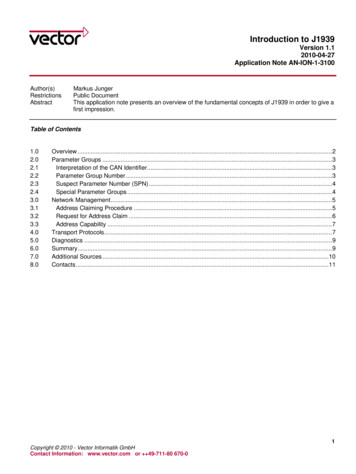
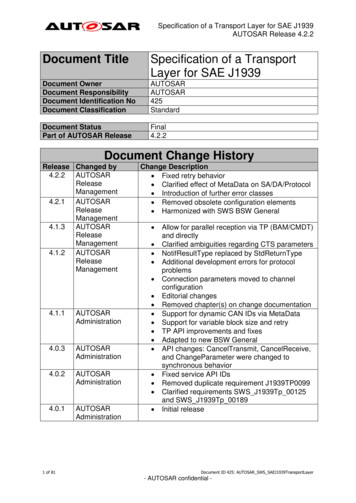
BridgeWay 2.0 Product DocumentationParameter LengthThe length of an individual parameter’s data.A parameter’s data may be contained in a single bit tomultiple bytes within the PGN message buffer. Note that datalength is not always in bytes but may be a number of bits.Parameter ResolutionThe scale and offset of a parameter’s data.The parameter data included in a PGN message is rawunsigned integer data. The scale and offset define thetranslation to convert the raw data to engineering units.J1939 PGN Message DefinitionsEach PGN has a message definition that specifies the size, transmission rate, and themessage layout. The message layout specifies how the data from the parameters in thegroup is arranged within the message buffer.PGN and Parameter Documentation ExamplesThere are many different ways that PGN message definitions are documented. Theexamples below show typical ways that parameters in the PGN 65263 Engine FluidLevel/Pressure message may be documented.J1939 Specification ExampleThe SAE J1939-71 specification contains the definitions for all standard PGNs. The PGNspecifications appear similar to the following representation:5.3.29 ENGINE FLUID LEVEL/PRESSURETransmission repetition rate:Data length:Data page:PDU format:PDU specific:Default priority:6Parameter group number:Byte:12345,6780.5 s8 bytes025423965 263 (00FEEF16)Fuel delivery pressureExtended crankcase blow-by pressureEngine oil levelEngine oil pressureCrankcase pressureCoolant pressureCoolant 5.385.2.5.73There is more information provided in the PGN definition than will be needed by the userresponsible for configuring the BridgeWay. The pertinent information for BridgeWayconfiguration is the transmission rate, the PGN number, and the parameter data offsets.Pyramid Solutions, Inc.3J1939 Data Mapping Explained
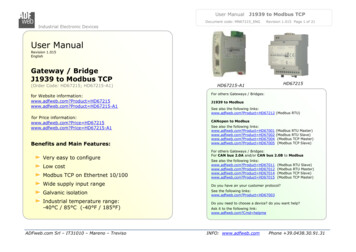
BridgeWay 2.0 Product DocumentationIt is important to note the following:1) In the specification, the offsets for parameter data in the message buffer aredefined by numbers starting with “1”. In the above example, Fuel Delivery Pressuredata is at the front byte or bit of the message (byte 1), while Engine Oil Pressure isin the 4th byte. When configuring BridgeWay I/O, message offsets are used ratherthan byte numbers, with message offset”0” being the front (i.e. first byte or bit) ofthe message buffer.2) Data transmitted in the PGN is “Raw” and may require scaling to arrive at theactual data value the PGN data represents. The following section defines wherethe scaling information is found.The PGN definition describes where the data is located in the message; however, thedescription of the actual data is found in the individual parameter descriptions. Thesection numbers to the right of the message buffer layout, specify where to find theparameter definitions.For instance, in the above example, the parameter definition for Engine Oil Pressure is insection 5.2.5.28 and may appear as follows:5.2.5.28 Engine Oil Pressure Gage pressure of oil in engine lubrication system as provided by oil pump.Data Length:Resolution:Data Range:Type:Suspect Parameter Number:Reference:1 byte4 kPa/bit gain, 0 kPa offset0 to 1000 kPa (0 to 145 psi)Measured1005.3.29The parameter definition gives the application or controls developer the rest of the storyon the data that is in the PGN message. The definition contains the actual parameter datalength, the scaling used to convert the “Raw” parameter data transmitted on the J1939network to engineering units, and the valid range of the data.The only information detailed above, pertinent to BridgeWay configuration is the datalength. The scaling and range information is useful for the application or controlsdeveloper who will use scaled or “cooked” data in their application or logic forprogrammatic purposes or when the data will be displayed for the end customer on anHMI or other display device. Likewise, the SPN may be useful for understandingdiagnostics.Note that a cross reference is included in the definition from the parameter back to thePGN definition section with which the parameter is grouped.Pyramid Solutions, Inc.4J1939 Data Mapping Explained
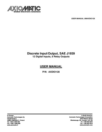
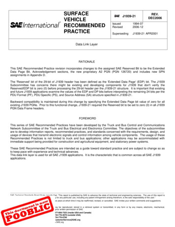
BridgeWay 2.0 Product DocumentationParameter Table ExampleIn some cases, equipment vendors and engine OEMs may provide a table that defines allthe PGNs / parameters that are available over the J1939 data link. These tables generallyprovide all the information needed for BridgeWay configuration and for the application orcontrols developer.The following is an excerpt from a table for the parameters in the PGN 65263 Engine FluidLevel/Pressure group.ParameterPGNSPNOffset7 bytesDataLength1 byteUpdateRate500msCoolant Level65263111Coolant Pressure652631096 bytes1 byte500msCrankcase Pressure652631014 bytes2 bytes500msEngine Oil Level65263982 bytes1 byte500msEngine Oil Pressure652631003 bytes1 byte500msExtended Crankcaseblow-by PressureFuel DeliveryPressure65263221 byte1 byte500ms65263940 bytes1 byte500msScaling0.4 %/bit0 % offset2 kPa/bit0 kPa offset0.0078 kPa/bit-250 kPa offset0.4 %/bit0 % offset4 kPa/bit0 kPa offset0.05 kPa/bit0 kPa offset4 kPa/bit0 kPa offsetRange0-100 %0-500 kPa-250-251.99 kPa1-100 %0-1000 kPa0-12.5 kPa0-1000 kPaFor the user responsible for configuring the BridgeWay, each parameter row contains thePGN number, offset into the message buffer, data length, and the expected transmissionrate. For the application and controls developer, the scaling, valid range and SPN aredefined for the parameters.Pyramid Solutions, Inc.5J1939 Data Mapping Explained
BridgeWay 2.0 Product DocumentationDetermining the BridgeWay Data Table LayoutAn important task when setting up the BridgeWay is determining how parameter data isgoing to be placed in the module’s data table. Although BWConfig will allow you to startadding parameters to the BridgeWay I/O tables and let the data end up where it falls, it issuggested that more thought be put into this process, to make the application or controlsdevelopment more straight-forward.Generally, placing parameters on word (16-bit) boundaries in the data table is suggested;however, this is somewhat controller dependent (i.e. some controllers are “little endian”and others are “big endian” regarding how memory values are accessed and stored). Thefollowing sections discuss suggested data table layouts for each type of controller.Note that J1939 PGN parameter data is stored in little endian format.Data Table Layout for Modbus RTU and Modbus TCP (Big Endian)It is suggested that parameters be mapped on 16-bit word boundaries in the BridgeWayfor applications with Modbus (big endian) controllers. This will result in individualparameters being conveniently mapped to individual Modbus (16 bit) registers, which willbe very useful and efficient for the application and controls developers.The Swap I/O Bytes option (checkbox) should be set (checked) in the BridgeWayconfiguration using BWConfig. This will ensure that data in the registers is in the properorientation to be read by the Modbus controller.Caveat: Parameter data with a length larger than 16 bits will span multiple Modbusregisters. Although the data in each register will be oriented correctly using this approach,the order of the data in the spanned registers will need to be manipulated in thecontroller. The least significant word will appear first in the register table. Hence a 4-byte(2 word) value will have the low word in the first register and the high word in the secondregister of the data table. This is reversed from what a Modbus controller expects and willrequire some manipulation by the Modbus controller logic or code to properly orient themultiple register data value.Important! All data is swapped once the Byte Swapping option is checked, includingoutgoing data (i.e. data coming into the BridgeWay data table from J1939 will be swappedand data sent to the BridgeWay output table by the application or controller will beswapped).Pyramid Solutions, Inc.6J1939 Data Mapping Explained
BridgeWay 2.0 Product DocumentationData Table Layout for EtherNet/IP (Little Endian)When determining the mapping boundaries for EtherNet/IP it must be determined howthe controller is going to use the data. ControlLogix controllers allow the connection datato be configured as bytes, 16-bit words, or 32-bit double words. Other EtherNet/IPscanners may treat the connection data as a simple string of bytes.If the connection data is to be treated as bytes, parameter data can be mapped on 8-bitboundaries. If mapped this way, any data larger than a single byte will have to bemanipulated by the controller program.When choosing the connection data format in the controller (in the case of ControlLogix)the size of the parameters must be taken into account. If all parameters are 8 bits or less,then the connection format can be configured as SINT (8-bit) data. If any of theparameters are larger than 8 bits, it may be beneficial to configure the connection formatas INT (16-bit) or DINT (32-bit) data. The mapping boundaries in the BridgeWay should beset according to the selected connection configuration.Pyramid Solutions, Inc.7J1939 Data Mapping Explained
BridgeWay 2.0 Product DocumentationConfiguring the BridgeWay I/O MappingOnce the J1939 parameters have been identified, their details collected, and the datatable layout has been determined, all that’s left is to enter all the information into theBridgeWay I/O configuration using BWConfig.Configuration AttributesFull details of the I/O configuration attributes can be found in the correspondingBridgeWay user manual. The table below describes how the information collected above,pertains to the BridgeWay configuration for input and output data points.PGNThe PGN of the group associated with the parameter as specified inthe PGN definition or by the parameter table.PriorityThe priority of the message as specified in the PGN definition.Care should be taken when assigning the Priority to an outgoingmessage. If it is unclear which priority to use, consult the ECU vendor.If it is still unclear use priority 6.Note that the Priority is only used when configuring Output I/Opoints; message priority is ignored when filtering messages for InputI/O points.Data TableOffsetThe offset for each parameter should be set according to the desireddata table layout. e.g. If a 16-bit boundary layout is desired, the offsetshould be set to an even byte boundary.Note that the table offset will auto-increment based on the datalength of the previous parameter and the word size selected; you mayor may not be required to reset the value when configuring the nextparameter.Data LengthPyramid Solutions, Inc.The length of the parameter data as specified in the parameterdefinition.8J1939 Data Mapping Explained
BridgeWay 2.0 Product DocumentationTargetAddressThe address of the ECU that is producing the parameter may bespecified in the parameter table or by the vendor.When configuring Input I/O points, in most cases the address may beset to 255 (don’t care) so that the parameter data will be capturedregardless of its source.When configuring Output I/O points, the address should be set asspecified by the vendor. Although it may be ok to broadcast somedata, in most cases the data which the BridgeWay will be sending willneed to be directed to a particular ECU.Update RateFor input parameters, the update rate must be set if the PGN’sdefined transmission rate is “on request”; otherwise the update ratecan be set to 0.For output parameters, the update rate should be set according tothe vendor’s specification in the parameter table.MessageOffsetPyramid Solutions, Inc.The offset into the message buffer for the parameter data specifiedby the PGN definition or by the parameter table.9J1939 Data Mapping Explained
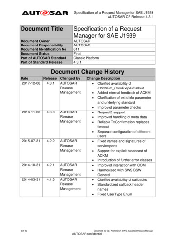
BridgeWay 2.0 Product DocumentationExample ConfigurationInput I/O ExampleUsing the information from the parameters defined for PGN 65263 above, the followingexample shows how to configure the BridgeWay to receive the Oil Pressure, CrankcasePressure and Fuel Pressure parameters.The data table is using 16-bit boundaries for parameter data. Note that the table offsetsare all on even bytes. Since the Oil Pressure parameter is only 8 bits in length; a byte wasskipped in the table when setting the table offset for the second parameter.The data lengths for each parameter were taken from the parameter table. The lengthsfor Oil, Crankcase, and Fuel pressure are 1, 2, and 1 byte respectively.Since PGN 65263 is transmitted every 500ms, the update rate was set to 0 since theBridgeWay will not have to send a request for the PGN.Note that it is recommended that you do not request the PGN (i.e. set the rate to otherthan 0) if the PGN is already being automatically transmitted by the ECU.The message offsets have been set according to the parameter offsets in the PGNdefinition. BWConfig represents offsets in “bits (bytes, bits)” format. Therefore, OilPressure is in byte 4 of the message buffer or offset 24 bits (3 bytes, 0 bits) from thebeginning of the buffer using 0 as the starting data offset. Crankcase Pressure is in bytes 5and 6, or offset 32 bits (4 bytes, 0 bits). Fuel pressure is at the beginning of the messagebuffer, byte 1 or offset 0 bits (0 bytes, 0 bits) as indicated in the table shown above.From the standpoint of a PLC scanning the BridgeWay, the data will appear in the inputtable as follows. Note that some BridgeWays (BW4031) insert status data at the front ofthe table offsetting the gister300033000430005Pyramid Solutions, Inc.BW2031ModbusRegisterData Description30001 Oil Pressure30002 Crankcase Pressure30003 Fuel Pressure10J1939 Data Mapping Explained
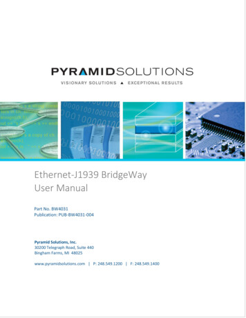
BridgeWay 2.0 Product DocumentationOutput I/O ExampleThe example that follows will illustrate a configuration to allow a controller to set theengine speed using PGN 0 through the BridgeWay.The following is an excerpt from a parameters table showing the parameters in the PGN 0,Torque/Speed Control.ParameterControl ModeControl ConditionControl PriorityRequested Speed /Speed LimitRequested Torque /Torque LimitPGNSPNOffset0 bits2 bits4 bits1 byteDataLength2 bits2 bits2 bits2 83 bytes1 byte10msScaling0.125 RPM/bit0 RPM offset1 %/bit-125 % offsetRange0 – 8031 RPM-125 – 125 %The configuration will allow control of the engine speed through the BridgeWay; hencethe Requested Speed and the control bit parameters are mapped to the output table.The data table is using 16-bit boundaries for parameter data. Note that the table offsetsare all on even bytes. Even the control bit parameters, which are all 2 bits each, have beenplaced so that they are each separated into their own words.The data lengths for each parameter were taken from the parameter table. The length forthe Requested speed is 2 bytes, while each control bit parameter is 2 bits in length.Based on the parameter table, PGN 0 is expected to be transmitted every 10ms; hence theupdate rate is set to 10ms in the I/O entries.The message offsets have been set according to the parameter offsets in the PGNdefinition. BWConfig represents offsets in “bits (bytes,bits)” format. Therefore, RequestedSpeed is in byte 2 of the message buffer or offset 8 bits (1 bytes, 0 bits) from the beginningof the buffer using 0 as the starting data offset. The control bit parameters are all withinthe first byte of the message at 2-bit offsets.Pyramid Solutions, Inc.11J1939 Data Mapping Explained
BridgeWay 2.0 Product DocumentationImportant Note: The PGN 0 message, like most J1939 messages, is 8 bytes. However, theBridgeWay only knows about the I/O data points that have been configured. In order toforce the BridgeWay to produce an 8-byte message, a pad bit must be configured that ismapped to the end of the message (bit 63, or byte 7, bit 7).From the standpoint of a PLC scanning the BridgeWay, the data will appear in output tableas follows. Note that some BridgeWays (BW4031) insert Command registers at the frontof the table offsetting the 410334000140002400034000440005Pyramid Solutions, Inc.Data DescriptionRequested SpeedSpeed Control ModeSpeed Control ConditionSpeed Control PrioritySpeed Control J1939 Message Padding12J1939 Data Mapping Explained
BridgeWay 2.0 Product DocumentationSupportTechnical Product AssistanceIf you require BridgeWay product technical support by phone: Call 248-549-1200 Dial 0 for the Operator Ask for BridgeWay SupportIf you require support by email: productsupport@pyramidsolutions.com Subject: “BridgeWay Support Request” Provide a detailed explanation of your question or issue in the email text.You can also obtain BridgeWay-related files and information online at the following nnectivity-support/Contact InformationPyramid Solutions, Inc.30200 Telegraph RoadSuite 440Bingham Farms, Michigan 48025Phone: 1-248-549-1200Toll free: 1-888-PYRASOLFax: 1-248-549-1400Website: www.pyramidsolutions.comPyramid Solutions, Inc.13J1939 Data Mapping Explained
J1939 Message Terminology Parameter A specific data element within a PGN message. Each parameter has a description, resolution, range, scaling, offset and data size defined by the vendor. Standard parameters are defined in the SAE J1939-71 specification. PGN Parameter Group Number Parameters are grouped by common purpose and assigned a PGN.