Transcription
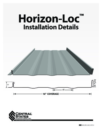
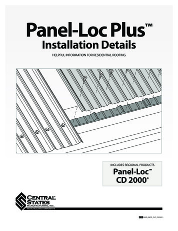
Panel-Loc Plus Installation DetailsHELPFUL INFORMATION FOR RESIDENTIAL ROOFINGINCLUDES REGIONAL PRODUCTSPanel-Loc CD 2000 C E GUID INSTL PLP 210101.1
We promise to improve your businessby accurately providing quality productsright when you need them. Every time.Visit our website for more product information, testing, installation guides, energyratings, warranties, photo gallery, color visualizer, and more.centralstatesmfg.com
INDEXImportant Information, Tools . . . . . . . . . . . . . . . . . 4Safety . . . . . . . . . . . . . . . . . . . . . . . . . . . . . . . . . . . . . . . . 5Care and Handling . . . . . . . . . . . . . . . . . . . . . . . . . . . . 5Field Cutting, Drilling, Fastening . . . . . . . . . . . . . . 6Fastener Spacing . . . . . . . . . . . . . . . . . . . . . . . . . . . . . 7Roof Preparation . . . . . . . . . . . . . . . . . . . . . . . . . . . . . 8-9Substructure Squareness . . . . . . . . . . . . . . . . . . . . . 10-11Installation Overview . . . . . . . . . . . . . . . . . . . . . . . . . 12-13Installing the First Panel . . . . . . . . . . . . . . . . . . . . . . 14-15Installing Sidelap Panel . . . . . . . . . . . . . . . . . . . . . . . 16Installing Endlap Panel . . . . . . . . . . . . . . . . . . . . . . . 17Residential Fascia Trim . . . . . . . . . . . . . . . . . . . . . . . . 18-19Residential Drip Edge . . . . . . . . . . . . . . . . . . . . . . . . . 20-21Residential Eave Trim . . . . . . . . . . . . . . . . . . . . . . . . . 22-23Valley Trim . . . . . . . . . . . . . . . . . . . . . . . . . . . . . . . . . . . . 24-25Gambrel Trim Lower . . . . . . . . . . . . . . . . . . . . . . . . . . 26-27Gambrel Trim Upper . . . . . . . . . . . . . . . . . . . . . . . . . . 28-29Residential Rake Trim . . . . . . . . . . . . . . . . . . . . . . . . . 30-31Ridge Cap . . . . . . . . . . . . . . . . . . . . . . . . . . . . . . . . . . . . 32-33Sidewall Trim . . . . . . . . . . . . . . . . . . . . . . . . . . . . . . . . . 34-35Endwall Flashing . . . . . . . . . . . . . . . . . . . . . . . . . . . . . 36-37NOTICE: This document illustrates conditions and details that are recommended for this product to minimize thenumber of potential water penetrations. Each project may have specific situations in which alternate methods maybe acceptable. A qualified contractor is able to adapt methods to a particular project.C E N T R A L S TAT E S M A N U FA C T U R I N G , I N C .Effective 01/2022 Information subject to change3
IMPORTANT INFORMATIONThis manual contains suggestions andguidelines on how to install Panel-Loc Pluspanels. The drawings in this guide are forillustration purposes only and may notapply to all building designs or productapplications. The installation details shownare proven methods of construction, butare not intended to cover all instances,building requirements, designs, or codes. Itis the responsibility of the designer/installerto ensure that the details meet particularbuilding requirements. The designer/installermust be aware of, and allow for, expansion/contraction of roof panels. The details mayrequire changes or revisions due to eachproject’s conditions.There are certain minimum live, snow,dead, collateral, and wind loads that a roofmust generally be designed to support.Consult local building officials to determinethe appropriate building design loadrequirements. A professional engineershould be consulted for all roof systemNOTEdesigns. It is the buyer’s responsibility toverify all applicable code requirements,check all measurements, and determinesuitability of product for the job. The buyeris also responsible for determining lengthsand quantities needed. Prior to ordering andinstalling materials, all dimensions should beverified with field measurements. Impliedwarranties of merchantability and fitnessfor a particular purpose are disclaimed.All Panel-Loc Plus instructions assume that aqualified firm or individual has been contactedregarding application of this product. Failureto comply with stated recommendationsrelieves the manufacturer of responsibility forany damage or deterioration of the productincurred and voids any applicable warranty.Central States Manufacturing reserves theright to modify, without notice, informationin this guide. If you have questions regardingproper installation of Panel-Loc Plus orinformation not included in this guide,contact your salesperson.Installation details shown also apply to Panel-Loc and CD2000 profiles.Follow the fastener spacing listed in their product guides at centralstatesmfg.com.TOOLS & EQUIPMENT Gloves Electric Metal Shear Safety Glasses Cordless Drill Snips/hand shear Caulking Gun Tape Measure Blind Rivet Tool Chalk Line4C E N T R A L S TAT E S M A N U FA C T U R I N G , I N C .Effective 01/2022 Information subject to change
CARE AND HANDLINGSAFETYEach job site presents different hazards;therefore it is the responsibility of thecontractor to determine the safest wayto install Panel-Loc Plus based on therecommended instructions contained inthis guide and provide crew members withappropriate safety measures. If you must walkon a metal roof, take great care. Metal panelscan become slippery, so always wear shoeswith non-slip soles. Avoid working on metalroofs during wet conditions, when the panelscan become extremely slippery. Walking orstanding on a metal roof which does not havea plywood or other deck beneath it is notrecommended. However, if you must do so,always walk on the purlins, never between.OSHA safety regulationscomplied with at all times.shouldbeAlways wear heavy gloves when working with steel panels to avoid cuts fromsharp edges. If power cutting or drilling steel panels, always wear safety glasses toprevent eye injury from flying metal fragments.RECEIVING MATERIALSHANDLINGWhen unloading panels, extreme cautionmust be employed. Care needs to be usedwhen unloading panels with a forklift. Paneledges and underside paint may becomedamaged if the forklift driver does not usecaution.When unbundling the panels, never dragthem across the surface of one another. Thismay cause scratches across the underneathpanels. It is recommended that the panels be“rolled” off the top of the bundle to preventscratching. Panels should only be lifted andcarried by their sides. Panel edges are verysharp, therefore, safety equipment should beworn by all workers handling the material.STORAGEAll materials should be stored in a dry place,preferably under a roof. Panels and trim aresubject to staining and premature rustingwhen water sits upon, or becomes trappedbetween them. You may stand panels on endand fan them out at the bottom to provideair circulation and moisture run off. If spacedoes not allow for this, the panels should beseparated, blocked off the ground at least12 inches to allow air flow and stored at anincline to encourage drainage. The panelsshould then be covered in a manner to stillallow airflow through the sheets. Do not usea plastic cover, as this may cause the panelsto sweat or condensation to occur. Failure toproperly store panels and trim could resultin product failure that is not covered bymanufacturers warranty.CAUTIONRemove the protective strippable filmfrom trim prior to installation. The longerstrippable is left on the material, the harder itwill be to remove.FOOT TRAFFICCare of metal panels and flashings must beexercised throughout installation. Foot trafficcan cause distortion of panel and damage tofinish. Traffic over the installed roof must bekept to an absolute minimum.If walking on the roof panels is unavoidable,walk only on the minor ribs to minimizedamage.Strippable film on Textured panels and trim must be removed within 30 days ofmanufacture date. Strippable that is left on for more than 30 days may be hard to peel offand is not a reason for a refund or replacement from the manufacturer.C E N T R A L S TAT E S M A N U FA C T U R I N G , I N C .Effective 01/2022 Information subject to changeCAUTION5
CUTTING AND DRILLINGFIELD CUTTINGCentral States recommends tin snips/handshears, electric nibblers or a profile shear tocut metal panels and trim. All product surfacesshould be free of debris at all times. Installedsurfaces should be wiped clean at the endof each work period. Never cut panels overmetal surfaces. When cutting metal panels,always wear heavy gloves to avoid cuts fromsharp edges and safety glasses to prevent eyeinjury.Central States discourages the use of a powersaw that may generate hot metal shavings.Hot shavings can stick to the painted surface.If loose shavings are not removed from thepanel surface immediately they will begin tocorrode and shorten the life of the product.One method of preventing this problem is toflip the panel over when cutting and only cutone panel at a time. This allows you to brushshavings off of the back of the panel andhelps to avoid damaging the painted finish.Make sure that stacks of panels are away fromthe cutting area so shavings do not blowonto other panels.DRILLINGAlways use a cover sheet underneath yourpanel if you are predrilling fastener holes. Donot predrill more than one panel at a time.Predrilling multiple panels can cause shavingsto become embedded in interior panels.Brush away any loose shavings immediately.CAUTION Shavings created by saw cutting or drilling may cause the panel to rust and couldresult in product failure that is not covered by manufacturers warranty.FASTENINGFastener length will be determined by thesubstrate under the panel. Use a fastener withwasher and drive it into the flats of the panelat every purlin or 9" on center, based on thefastener spacings shown on page 7.CORRECTThe fastener's washer should be compressedfirmly against the metal, but not overdrivenwhich can cause leakage. If a fastener missesa purlin, remove it and use caulk or a stitchscrew to fill the hole.TOO LOOSEOVERDRIVENOverdriven fasteners can cause the washer to fail and leak or a dimpleCAUTION in the panel which can collect water and cause rust.6C E N T R A L S TAT E S M A N U FA C T U R I N G , I N C .Effective 01/2022 Information subject to change
FASTENER SPACINGFollow the suggested fastener patterns below for interior or panel termination.Screws may be placed in either the flat or the rib. In the overlap condition, avoid usingfasteners in the major rib as this may damage the siphon groove.Fastener pattern at panel termination (Eave, endlap, valley)9"9"Fastener pattern at interior of panel9"9"SIPHON GROOVEPanel-Loc Plus has two vertical edges,the overlap and the sidelap. The sidelapedge has a specific bend in the lastmajor rib, called a siphon groove. Whenthe overlap edge is installed on top ofthe sidelap edge, it creates an air gapthat prevents water from wicking underthe panel. Panels should be installedwith the overlap facing away from theprevailing wind.Do not damage thesiphon groove by using astitch screw on top of themajor rib or clog it withbutyl tape.SIPHON GROOVEOVERLAPSIDELAPPREVAILINGWINDSOVERLAPSIDELAPC E N T R A L S TAT E S M A N U FA C T U R I N G , I N C .Effective 01/2022 Information subject to change7
ROOF PREPARATIONPanel-Loc Plus can be installed over existing shingles,over solid decking or over purlins/open framing.It is the responsibility of the contractor to ensure asuitable substrate prior to the application of PanelLoc Plus. Substructures should be designed to meetall necessary code requirements. Green lumber isnot recommended as moisture can damage themetal panels and cause fasteners to back out.Distortion in the panel caused by an unevensubstrate, ripples, or laps in the vapor barrier,debris, protruding nails and staples, button capnails, etc., are not defects in the materials and arenot the responsibility of Central States. To minimizedistortions from an uneven substrate, use Retroeaseor 1x4 furring strips.2'EXISTING SHINGLES1. Make sure any existing decking is smooth, level and in good condition.Remove any damaged shingles or debris that might interfere with installation.2. Apply 30 lb. felt or synthetic underlayment using nails or staples.3. Apply 1x4 furring strips or Retroease horizontally, every 2' on center.These strips will act as purlin framing that you will fasten panels to.4. Check for roof squareness. Follow guidelines on page 10.5. Begin installation of trim and panels following guidelines on pages 12-13.CAUTION8Check local codes when installing metal roofing over existing shingles. It is notrecommended to install over more than 2 layers of shingles. Shingles may rotbetween layers due to trapped moisture, or substructure may fail due to weightof shingles and metal roof.C E N T R A L S TAT E S M A N U FA C T U R I N G , I N C .Effective 01/2022 Information subject to change
ROOF PREPARATIONSOLID DECKING1. Make sure decking is smooth, level and in good condition. Remove anydebris that might interfere with installation.2. Apply 30 lb. felt or synthetic underlayment using nails or staples.3. Check for roof squareness. Follow guidelines on page 10.4. Begin installation of trim and panels following guidelines on pages 12-13.OPEN FRAMINGPanel-Loc Plus can be install directly over purlins/wood framing. Maximum purlinspacing is 2'. This method should only be used for heated spaces if adequateprotection against condensation is used. Without this protection, the underside ofthe panel may collect condensation and drip into structure.1. Check for roof squareness. Follow guidelines on page 10.2. Begin installation of trim and panels following guidelines on pages 12-13.C E N T R A L S TAT E S M A N U FA C T U R I N G , I N C .Effective 01/2022 Information subject to change9
SUBSTRUCTURE SQUARENESSThe installer should check the roof deck forsquareness before installation. Panel distortionmay occur if not applied over properly aligned anduniform substructure. Several methods can beused to verify squareness of the structure for properinstallation of the panels.CAUTIONIf the structure is out of square, you can use the 3-4-5triangle method to create an alignment line to startyour first run of panels.Correct any squareness issues as early in the installation as possible. It might notappear to be a problem at the beginning, but if left uncorrected it will be verynoticeable in the end.RIDGEOVERVIEWThe main goal is to create a trianglewith sides that are 3', 4' and 5'. Whenthis is accomplished you know youhave a right angle at the eave torake and can create an alignmentline that is square.5'RAKE4'3'EAVERIDGESTEP 11. Starting at the eave and 1/2" fromthe rake, place a nail at POINT A2. From POINT A, measure over 3'parallel with the eave and place anail at POINT B.RAKE1A1032BC E N T R A L S TAT E S M A N U FA C T U R I N G , I N C .Effective 01/2022 Information subject to changeEAVE
CRIDGESTEP 23. Hook one tape measure toPOINT A and run it up therake, approximately 4' towardsthe ridge.44"55"3"3RAKE44"32"23"22"1"11"4. Hook a second tape measureto POINT B and run it diagonaltowards the first tape measure toapproximately 5'.A1BBEAVE5. Mark POINT C with a nail wheretape measure one at 4' meetstape measure two at 5'.CSTEP 36. Snap a chalk line from the nailsat POINT A and POINT C. This isyour alignment line to start yourfirst panel on.7. Additional reference lines canbe marked ahead of panelinstallation by snapping a parallelline 10' from your first line. Thenas panels are installed you canmeasure points at the eave andridge against this second line tosee if the panels are still runningsquare.RIDGERAKEAC E N T R A L S TAT E S M A N U FA C T U R I N G , I N C .Effective 01/2022 Information subject to changeEAVE11
INSTALLATION OVERVIEWInstallation order will vary from roof to roof. Recommended installation of Panel-Loc Plus is shown below.The contractor will determine which conditions apply.12MOISTURE BARRIERFASCIA TRIM3EAVE TRIMNOTE: Install any additional ice and watershield in valleys if appropriate at this time.4VALLEY TRIM125PANELS6GAMBREL TRIMSC E N T R A L S TAT E S M A N U FA C T U R I N G , I N C .Effective 01/2022 Information subject to change
7PANELS10SIDEWALL8RAKE TRIM11ENDWALL9RIDGECAP12COMPLETEDC E N T R A L S TAT E S M A N U FA C T U R I N G , I N C .Effective 01/2022 Information subject to change13
INSTALLING THE FIRST PANELPanels should be installed in the correct sequenceas shown on pages 12-13. Install panels with thesidelap facing away from the prevailing wind.SIDELAPPREVAILINGWINDSCAUTION14Copper metallic panels must be installed in the same direction!See directional arrows or stickers provided with your metal panel order.C E N T R A L S TAT E S M A N U FA C T U R I N G , I N C .Effective 01/2022 Information subject to change
1. Start the first panel at the alignmentline you created on page 11.RIDGE2. The panel should overhang from theeave a desired amount. If installinggutters, a 1" overhang is suggested.An overhang of 6" or more may notsupport weight of snow or debris.3. Fasten at the eave according to thefastener pattern below. The fastenersshould penetrate through the insideclosure, through the eave trim andinto the substrate below.4. Continue by fastening the panelevery 2' running towards the ridge.Use the interior panel fastenerpattern.2'5. Continue with panel run usingsidelaps. If necessary use an endlapcondition shown on page 17.ALIGNMENTLINERAKEEAVEFastener pattern at panel termination (Eave, endlap, valley)9"9"Fastener pattern at interior of panel9"9"Fastener spacing for Panel-Loc or CD2000 can be found in product guides at centralstatesmfg.com.C E N T R A L S TAT E S M A N U FA C T U R I N G , I N C .Effective 01/2022 Information subject to change15
INSTALLING SIDELAP PANELAfter the first panel is secure, proceed with the nextpanel by overlapping it on the side. Continue withfastener pattern shown on page 15.OVERLAPPREVAILINGWINDSDo not damage the siphon groove by using a stitch screwCAUTION on top of the major rib or clog it with butyl tape.16C E N T R A L S TAT E S M A N U FA C T U R I N G , I N C .Effective 01/2022 Information subject to change
INSTALLING ENDLAP PANELThis application may not be required.1. Starting at 3" from the end of thepanel to be lapped, apply a line ofbutyl tape over the ribs.2. Overlap the next panel 6".3. Fasten the two panels togetherthrough the butyl tape and intothe substrate below. This should beabout 3" back from the overlappingpanel.3"6"4. Continue by fastening the panelevery 2' running towards the ridge.Use the interior panel fastenerpattern.C E N T R A L S TAT E S M A N U FA C T U R I N G , I N C .Effective 01/2022 Information subject to change17
RESIDENTIAL FASCIA TRIMPANEL-LOC PLUS#10 SCREWINSIDE CLOSUREAND BUTYL TAPE30 LB. FELT PAPER(MINIMUM)SOLID DECKINGRESIDENTIALEAVE TRIMWAFER HEADSCREWFASCIA BOARDRESIDENTIALFASCIA TRIM#10 SCREWILLUSTRATED TRIMS:Choose trim with leg length thatbest covers the fascia board.FASCIA TRIMRFT312RFT512RFT712Paintedside18C E N T R A L S TAT E S M A N U FA C T U R I N G , I N C .Effective 01/2022 Information subject to change
PANEL-LOC PLUS30 LB. FELT PAPER(MINIMUM)WAFERHEADSCREWINSIDE CLOSUREAND BUTYL TAPE#10 SCREWSOLID DECKINGRESIDENTIALEAVE TRIMFASCIA BOARDRESIDENTIALFASCIA TRIMDIRECTIONS:1. Choose a RFT with a leg length that best covers thefascia board.2. Place RFT at fascia board and make sure roof feltoverlaps RFT.3. Fasten RFT to bottom of fascia board at 24" on center.4. Continue by installing either Residential Drip Edge orResidential Eave Trim.C E N T R A L S TAT E S M A N U FA C T U R I N G , I N C .Effective 01/2022 Information subject to change19
RESIDENTIAL DRIP EDGENOTE: Residential Drip Edge is not recommended when using seamless gutters.Choose Residential Eave Trim instead.PANEL-LOC PLUS#10 SCREWINSIDE CLOSUREAND BUTYL TAPE30 LB. FELT PAPER(MINIMUM)SOLID DECKINGWAFER HEADSCREWRESIDENTIALDRIP EDGERESIDENTIALFASCIA TRIMILLUSTRATED TRIMS:Specify pitch when ordering trim.RESIDENTIAL DRIP EDGERDCpitch20PaintedsideC E N T R A L S TAT E S M A N U FA C T U R I N G , I N C .Effective 01/2022 Information subject to change
PANEL-LOC PLUS30 LB. FELT PAPER(MINIMUM)WAFERHEADSCREW#10 SCREWRESIDENTIALDRIP EDGESOLID DECKINGRESIDENTIALFASCIA TRIMINSIDE CLOSUREAND BUTYL TAPETIPWhen overlapping RDCs, trim off kickout at bottom of trimon underlapping trim.DIRECTIONS:1. Fasten the RDC to the roof deck as shown withappropriate fastener. Fastener spacing is not importantbecause the panel will fasten through the trim in alater step. Wafer head screws are recommended forthis portion of application. If you are using a hex-headscrew, fasteners should be placed appropriately tobe hidden under the panel rib. Fasteners should beplaced no more than .75” from the top of trim to allowfor closure placement in later step.2. Place a run of butyl tape directly between edge offastener and edge of roof. Then install inside closure ontop of the butyl tape. Place another run of tape on topof inside closure.3. Place panel on roof, aligning with inside closure. Theedge of the panel should be aligned with the edge ofthe RDC overhanging the fascia.4. Fasten panel according to fastener pattern, fasteningthrough the closure, into the roof.C E N T R A L S TAT E S M A N U FA C T U R I N G , I N C .Effective 01/2022 Information subject to change21
RESIDENTIAL EAVE TRIMNOTE: Use with seamless gutters applications.PANEL-LOC PLUS#10 SCREWINSIDE CLOSUREAND BUTYL TAPE30 LB. FELT PAPER(MINIMUM)SOLID DECKINGRESIDENTIALEAVE TRIMWAFER HEADSCREWRESIDENTIALFASCIA TRIMILLUSTRATED TRIMS:Specify pitch when ordering trim.RESIDENTIAL EAVE TRIMRETPaintedside22pitchC E N T R A L S TAT E S M A N U FA C T U R I N G , I N C .Effective 01/2022 Information subject to change
PANEL-LOC PLUS30 LB. FELT PAPER(MINIMUM)WAFERHEADSCREW#10 SCREWRESIDENTIALEAVE TRIMSOLID DECKINGINSIDE CLOSUREAND BUTYL TAPETIPWhen overlapping RETs, trim off kickout at bottomof trim on underlapping trim.DIRECTIONS:1. Fasten the RET to the roof deck as shown withappropriate fastener. Fastener spacing is not importantbecause the panel will fasten through the trim in alater step. Wafer head screws are recommended forthis portion of application. If you are using a hexhead screw, fasteners should be placed appropriatelyto be hidden under the panel rib. Fasteners should beplaced no more than .75” from the top of trim to allowfor closure placement in later step.2. Place a run of butyl tape directly between edge offastener and edge of roof. Then install inside closure ontop of the butyl tape. Place another run of tape on topof inside closure.3. Place panel on roof, aligning with inside closure. Theedge of the panel should be placed at the desiredoverhang of the fascia.4. Fasten panel according to fastener pattern, fasteningthrough the closure, into the roof.C E N T R A L S TAT E S M A N U FA C T U R I N G , I N C .Effective 01/2022 Information subject to change23
VALLEY TRIMVALLEYPANEL-LOC PLUSGRAYFLEX#10 SCREWSOLID DECKING30 LB. FELT PAPER(MINIMUM)WAFER HEADSCREWILLUSTRATED TRIMS:Specify pitch when ordering trim.VALLEYVT1VT2Paintedsidepitchpitch24C E N T R A L S TAT E S M A N U FA C T U R I N G , I N C .Effective 01/2022 Information subject to change
PANEL-LOC PLUSVALLEY30 LB. FELT PAPER(MINIMUM)WAFER HEADSCREW#10 SCREWGRAYFLEXEAVE TRIMDIRECTIONS:1. Place the VT1 into the valley of the roof so that bothsides sit flat on the roof decking.2. Prior to fastening the VT1, the lower end must be cut toline up with the edge of the roof sections.3. In most cases the top end of the VT1 will meet anotherVT1 coming from the other side of the roof section.The upper ends of each piece will need to be trimmedso that they can be overlapped.4. The VT1 should be fastened to the roof deck no morethan 2” from the outer edges. Place enough fastenersto secure VT1 until roof panel is applied. Wafer headscrews are recommended for this portion of application.If you are using a hex-head screw, fasteners should beplaced appropriately to be hidden under the panel rib.5. Grayflex expandable foam is the recommendedclosure for valley installations.6. When installing panels in a valley, the lower end of thepanels should stop 3-4 inches from the center of thevalley. Use endlap fastener pattern.C E N T R A L S TAT E S M A N U FA C T U R I N G , I N C .Effective 01/2022 Information subject to change25
GAMBREL TRIM LOWER (TRANSITION TRIM)PANEL-LOC PLUSWAFER HEADSCREWINSIDE CLOSUREAND BUTYL TAPEGAMBREL TRIMLOWER#14 LAP SCREW#10 SCREWPANEL-LOC PLUS30 LB. FELT PAPER(MINIMUM)SOLID DECKING#10 SCREWOUTSIDE CLOSURETIPAlways overlap Gambrel Lower trims the length oftwo ribs to reduce a wavy appearance.ILLUSTRATED TRIMS:Specify top and bottom pitchwhen ordering trim.GAMBREL TRIM LOWERGTLPaintedside26C E N T R A L S TAT E S M A N U FA C T U R I N G , I N C .Effective 01/2022 Information subject to change
INSIDE CLOSUREAND BUTYL TAPE#14 LAPSCREWWAFERHEADSCREWOUTSIDE CLOSUREAND BUTYL TAPEGAMBREL TRIMLOWER30 LB. FELT PAPER(MINIMUM)PANEL-LOC PLUSSOLID DECKINGBe careful to not press down hard on unhemmed leg of GTL when fastening.This could create a bend that might trap water.CAUTIONDIRECTIONS:1. The lower section of the roof transition with panelsmust be installed prior to installation of the GTL. Placeoutside closure near the upper end of the lower roofpanel where the transition trim will go.2. Place the GTL uphill until the top leg (unhemmed leg)rests against the upper section of roof decking and thebottom leg sits on the lower panel.3. Fasten the GTL through the closure into the lowerpanel section through each rib along the length of thetrim. Lap screws are recommended for this portion ofapplication.4. The upper leg of the GTL should be fastened 1” fromthe top of the trim into the roof decking. Placingthe fastener closer to the bend in the middle couldimpede later installation steps. Wafer head screws arerecommended for this portion of application. If youare using a hex-head screw, fasteners should be placedappropriately to be hidden under the panel rib.5. Before installing upper panels, place a run of butyl tapealong the length of the GTL approximately two inchesup from the bend. Then install inside closure on top ofbutyl tape. Place another run of butyl tape on top ofthe inside closure.6. Place the panel for the upper level of the transition,fastening through the closure into roof decking.C E N T R A L S TAT E S M A N U FA C T U R I N G , I N C .Effective 01/2022 Information subject to change27
GAMBREL TRIM UPPERPANEL-LOC PLUSINSIDE CLOSUREAND BUTYL TAPEWAFER HEADSCREWGAMBREL TRIMUPPER#10 SCREW#10 SCREW#14 LAP SCREWOUTSIDE CLOSUREAND BUTYL TAPE30 LB. FELT PAPER(MINIMUM)SOLID DECKINGPANEL-LOC PLUSTIPAlways overlap Gambrel Lower trims the length oftwo ribs to reduce a wavy appearance.ILLUSTRATED TRIMS:Specify top and bottom pitchwhen ordering trim.GAMBREL TRIM UPPERGTUpitch28PaintedsideC E N T R A L S TAT E S M A N U FA C T U R I N G , I N C .Effective 01/2022 Information subject to change
INSIDE CLOSUREAND BUTYL TAPEGAMBRELTRIMUPPERWAFERHEADSCREWOUTSIDE CLOSUREAND BUTYL TAPE30 LB. FELT PAPER(MINIMUM)#14 LAP SCREWPANEL-LOC PLUSSOLID DECKINGDIRECTIONS:1. The lower section of the roof transition with must beinstalled prior to installation of the GTU.2. Place a run of butyl tape near the upper end of thelower panel where the transition trim will go. Theninstall outside closure on top of butyl tape. Placeanother run of butyl tape on top of the outside closure.3. Place the GTU uphill until the top leg (unhemmed)rests against the upper section of roof decking. Thebottom leg should also rest against the bottom panel.4. Use appropriate fastener to attach the GTU throughthe closure into the lower panel section througheach rib along the length of the trim. Lap screws arerecommended for this portion of application.5. The upper leg of the GTU should be fastened 1” fromthe top of the trim into the roof decking. Placingthe fastener closer to the bend in the middle couldimpede later installation steps. Wafer head screws arerecommended for this portion of application. If youare using a hex-head screw, fasteners should be placedappropriately to be hidden under the panel rib.6. Before installing upper panels, place a run of butyltape along the length of the GTU approximately twoinches up from the bend. Install outside closure on topof butyl tape. Place another run of butyl tape in top ofoutside closure.7. Place the panel for the upper level of the transition.8. Starting run of screws for the upper panel shouldfasten through the closure into roof decking.9. Fasten the panel to the roof decking according to thefastener pattern.C E N T R A L S TAT E S M A N U FA C T U R I N G , I N C .Effective 01/2022 Information subject to change29
RESIDENTIAL RAKERESIDENTIALRAKE#10 SCREW#10 SCREWBUTYL TAPERESIDENTIALFASCIA TRIMSOLID DECKING30 LB. FELT PAPER(MINIMUM)PANEL-LOC PLUSILLUSTRATED TRIMS:RESIDENTIAL RAKERRTPaintedside30C E N T R A L S TAT E S M A N U FA C T U R I N G , I N C .Effective 01/2022 Information subject to change
PANEL-LOC PLUSRESIDENTIALRAKE#10 SCREWSOLID DECKINGRESIDENTIALFASCIA TRIMBUTYL TAPE30 LB. FELT PAPER(MINIMUM)DIRECTIONS:1. Install panel aligned with edge of roof.2. Apply butyl tape to the leg of the RRT that will befastened to the roof (the non-flat side). Extra widthof butyl tape should be hidden inside the trim, ratherthan exposed to the weather. To apply, unroll butyltape and stick to the trim. Leave backer on butyl tapeuntil just prior to installation.3. When ready to install the piece, peel the backer off ofthe butyl tape and align rake trim so that the face (flatside) of the RRT is against the fascia and the top of theRRT is at the same height as the panel rib.4. Install fastener through the hem and butyl tape intothe roof. Install another fastener into the face of theRRT and the fascia about an inch above the hem.Fasten the length of the trim following the fastenerpattern established at panel installation.C E N T R
5. Begin installation of trim and panels following guidelines on pages 12-13. 2' CAUTION Check local codes when installing metal roofing over existing shingles. It is not recommended to install over more than 2 layers of shingles. Shingles may rot between layers due to trapped moisture, or substructure may fail due to weight of shingles and .