Transcription
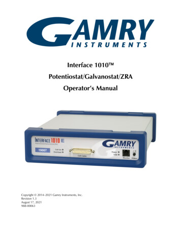
Interface 1010 Potentiostat/Galvanostat/ZRAOperator’s ManualCopyright 2014–2021 Gamry Instruments, Inc.Revision 1.3August 17, 2021988-00063
If You Have ProblemsIf You Have ProblemsPlease visit our service and support page at www.gamry.com/service-support/. This page contains informationon installation, software updates, and training. It also contains links to the latest available documentation. If youare unable to locate the information you need from our website, you can contact us via e-mail using the linkprovided on our website. Alternatively, you can contact us one of the following ne(215) 682-9330 9:00 AM 5:00 PM US Eastern Standard Time(877) 367-4267 Toll-free US & Canada OnlyPlease have your instrument model and serial numbers available, as well as any applicable software andfirmware revisions.If you have problems in installation or use of a system containing an Interface 1010, call from a phone next toyour computer, where you can type and read the screen while talking to us.We are happy to provide a reasonable level of free support for registered users of the Interface 1010Potentiostat/Galvanostat/ZRA. Reasonable support includes telephone assistance covering the normalinstallation, use, and simple customization of a computerized system containing an Interface 1010 connectedto a Windows -compatible computer.A service contract that extends both the hardware warranty and software update period is available at anadditional charge. Software updates do not include software enhancements offered to our customers atadditional cost.Enhancements to the Interface 1010 and Gamry’s standard applications software that require significantengineering time on our part can be performed on a contract basis. Contact us with your requirements.Limited WarrantyGamry Instruments, Inc. warrants to the original user of this product that it shall be free of defects resulting fromfaulty manufacture of the product or its components for a period of two years from the original shipment dateof your purchase.Gamry Instruments, Inc. makes no warranties regarding either the satisfactory performance of the Interface1010 Potentiostat/Galvanostat/ZRA including the software provided with this product or the fitness of theproduct for any particular purpose. The remedy for breach of this Limited Warranty shall be limited solely torepair or replacement, as determined by Gamry Instruments, Inc., and shall not include other damages.Gamry Instruments, Inc. reserves the right to make revisions to the system at any time without incurring anyobligation to install same on systems previously purchased. All system specifications are subject to changewithout notice.There are no warranties which extend beyond the description herein. This warranty is in lieu of, andexcludes any and all other warranties or representations, expressed, implied or statutory, includingmerchantability and fitness, as well as any and all other obligations or liabilities of Gamry Instruments,Inc.; including but not limited to, special or consequential damages.This Limited Warranty gives you specific legal rights and you may have others, which vary from state to state.Some states do not allow for the exclusion of incidental or consequential damages.No person, firm or corporation is authorized to assume for Gamry Instruments, Inc., any additional obligationor liability not expressly provided herein except in writing duly executed by an officer of Gamry Instruments,Inc.3
DisclaimersDisclaimersGamry Instruments, Inc. cannot guarantee that the Interface 1010 Potentiostat/Galvanostat/ZRA will work withall computer systems, operating systems, and third-party software applications/hardware/software.The information in this manual has been carefully checked and is believed to be accurate as of the time ofprinting. However, Gamry Instruments, Inc. assumes no responsibility for errors that might appear.CopyrightsInterface 1010 Potentiostat/Galvanostat/ZRA Operator’s Manual copyright 2014 2018 GamryInstruments, Inc., all rights reserved.Gamry Framework copyright 1989 2021 Gamry Instruments, Inc., all rights reserved.Interface 1010 , Interface 5000 , Reference 620 , Reference 3000TM, Reference 3000AETM,Reference 30K , LPI1010 , eQCM 10M , ECM8 , Gamry Framework , Faraday Shield , and Gamry aretrademarks of Gamry Instruments, Inc.Windows is a registered trademark of Microsoft Corporation.No part of this document may be copied or reproduced in any form without the prior written consent ofGamry Instruments, Inc.4
Table of ContentsTable of ContentsIf You Have Problems . 3Limited Warranty . 3Disclaimers . 4Copyrights . 4Table of Contents. 5Chapter 1: Safety Considerations . 9Inspection . 9Product Safety. 9AC Mains Connection to the Power Brick . 9Grounding in the Interface 1010 . 10Operation with Earth-grounded Cells and Auxiliary Apparatus . 10Temperature and Ventilation . 11Defects and Abnormal Stresses . 11Environmental Limits . 12Cleaning . 12Service . 13RF Warning . 13Electrical Transient Sensitivity . 13CE Compliance . 14RoHS Compliance. 14Chapter 2: Introduction . 15About this Manual . 15About the Interface 1010 . 15Software and Applications . 16Multichannel Systems . 16Front Panel Customization . 17Notational Conventions . 17Chapter 3: Installation . 19Initial Visual Inspection . 19Physical Location . 19Computer Requirements . 20Quick-start Guide for System Installation . 20Software Installation . 20Reboot your Computer after Software Installation . 21Power Cord and Power Connection . 21Power Up Test . 22USB Cables . 22Multiple Potentiostat Systems . 23Cell Cable Installation. 24Front Panel USB LED . 24Running the Framework . 24Framework Device Status Bar . 24Types of Interface 1010 instruments . 25Authorization Codes and Label. 26Firmware Update . 26The Interface 1010 Customization Label. 26Introduction to the Interface 1010 Customization Label . 26Label Sheet Provided with Each Interface 1010. 275
Table of ContentsProcedure to Change a Label. 27Chapter 4: Calibration . 31Introduction . 31DC Calibration . 31Cable Calibration . 32Procedure to calibrate the cable . 33Chapter 5: Cell Connections . 37Normal Cell Connections . 37ZRA-Mode Cell Connections . 38Membrane Cell Connections . 39Chapter 6: Panel Indicators and Connectors . 41Front Panel . 41Power Switch . 41The Power LED . 41Cell Cable Connector . 42Monitor Connector . 42The USB LED . 42Cell On LED. 43Overload LED . 44Customization Label Area . 45Rear Panel . 45Power In Jack . 45Chassis Ground . 46USB Port . 46User I/O Connector . 46Sync Port . 47Chapter 7: Instrument Circuitry . 49Interface 1010 Schematic/Block Diagrams . 49Chapter 8: Stability in Potentiostat Mode . 55Capacitive Cells and Stability . 55Improving Potentiostat Stability . 55Chapter 9: Measurement of Small Signals . 59Overview . 59Measurement System Model and Physical Limitations . 59Johnson Noise in Zcell . 60Finite Input Capacitance. 61Leakage Currents and Input Impedance . 61Voltage Noise and DC Measurements . 62Shunt Resistance and Capacitance . 62Hints for System and Cell Design . 62Faraday Shield. 62Avoid External Noise Sources . 63Length and Construction of the Cell Cable . 63Lead Placement . 63Cell Construction . 64Reference Electrode . 64Instrument Settings . 64EIS Speed . 64Ancillary Apparatus . 64Floating Operation . 65Appendix A: Interface 1010 Specifications . 676
Table of ContentsControl Amplifier . 67Differential Electrometer. 67Voltage Measurement. 67Current to Voltage Converter . 68Current Measurement . 68Potentiostatic Mode . 69Galvanostatic Mode . 69Environmental . 69General . 69Appendix B: Interface 1010 Cell Connector . 73Appendix C: I/O Connectors . 75User I/O Connector. 75Sync Port . 76Monitor Connector . 76I Monitor Signal . 77E Monitor Signal . 77Temperature Monitor Signal . 78External Signal In . 78Appendix D: Power LED Blink Codes . 81Normal Start-up . 81Failure in an electronics module . 81Severe problem . 81Error Messages and Limitations . 81Error Message This instrument is not authorized for Freq . 81Error Message This instrument is not authorized for IERange . 82Error Message This instrument is not authorized for ScanRate . 82Error Message This instrument is not authorized for SampleTime . 82Appendix E: Certifications . 83Declaration of Conformity: No. DOC-2017-CE-IFC1010 . 83Declaration of Conformity: No. DOC-2021-UKCA-IFC1010 . 84Appendix F: Heat in Interface 1010 Multichannel Systems . 85Introduction to Device Power-Dissipation. 85Potentiostat/Galvanostat Power Model . 85Discharging a Battery . 86Single Interface 1010 . 87Vertical Stacks . 87Interface Power Hub Systems . 87Appendix G: Capabilities of Various Models of Interface 1010 . 89Appendix H: Index . 937
Safety Considerations – InspectionChapter 1: Safety ConsiderationsYour Interface 1010 Potentiostat/Galvanostat/ZRA has been supplied in a safe condition. This chapter containsinformation and warnings that you must follow to insure continued safe operation of the Interface 1010.InspectionWhen you receive your Interface 1010 Potentiostat/Galvanostat/ZRA, inspect it for evidence of shippingdamage. If you note any damage, please notify Gamry Instruments Inc. and the shipping carrier immediately.Save the shipping container for possible inspection by the carrier.Warning: An Interface 1010 damaged in shipment can be a safety hazard. Do not operatedamaged apparatus until a qualified service technician has verified its safety. Tag a damaged Interface 1010to indicate that it could be a safety hazard.Product SafetyThe Interface 1010 has been designed, tested and certified to meet the requirements of EN 61010, Safetyrequirements for electrical equipment for measurement, control, and laboratory use. As defined in this standard,it is a Category II apparatus, with any “hazardous live voltages” protected by “reinforced insulation.”Most of the Interface 1010 circuitry is at voltages low enough to be considered safe. The Interface 1010contains a limited amount of internal circuitry that is at “hazardous live” voltages as defined in EN 61010 (thestandard mentioned above). “Reinforced insulation” (again defined in EN 61010) is used to reduce the risk ofelectrical shock caused by this hazardous live voltage.The majority of the Interface 1010’s circuitry does not contain voltages higher than 24 V DC. As ageneralization, input and output voltages in the Interface 1010 are limited to 24 V. This voltage level isconsidered safe.The “AC Adapter” supplied with the Interface 1010 is certified under EN 60950. The AC Adapter converts theAC mains voltage to 48 V DC, which is used to power the Interface 1010.Always use the AC adapter (power brick) supplied with your Interface 1010 to supply DC power to theinstrument.Caution: Use only Gamry-approved DC power sources with your Interface 1010. Otherpower sources may alter the performance and/or safety characteristics of the Interface 1010.AC Mains Connection to the Power BrickThe Interface 1010 does not connect directly to an AC Mains supply. Instead, the mains are connected todesktop AC adapter (power brick), which outputs 48 V DC, which in turn powers the Interface 1010.The Interface 1010’s AC Adapter is rated for operation from 100 to 240 V AC, 47 to 63 Hz.It should therefore be useful throughout the world.9
Safety Considerations – Grounding in the Interface 1010The Interface 1010 is normally provided with an AC line cord suitable for your location. This AC line cordconnects the AC mains to the AC power adapter. If your Interface 1010 has been provided without an AC linecord, or a cord that is not compatible with your local AC mains socket, obtain a line cord certified for use inyour country. Contact your local Gamry Representative or e-mail to techsupport@gamry.com if you areuncertain what AC line cord to use.Grounding in the Interface 1010The circuitry and the metal case of the Interface 1010 are not connected to an earth ground. If they wereconnected to earth ground, it would compromise the Interface 1010’s ability to make measurements inelectrochemical cells that contain earth-grounded metal. A few examples of such cells include autoclaves,metallographic stress apparatus, and detectors for capillary electrophoresis.Most electrochemical cells are isolated from earth ground, so isolation of the Interface 1010 from earth is notrequired. In these cases, connection of the Interface 1010 chassis to an earth ground may lower the noise seenin an electrochemical test. A Chassis Ground banana jack on the rear panel of the Interface 1010 easilyimplements this connection. Simply run a wire from this binding post to a suitable source of earth ground. Ablack 1.2-meter wire is provided with the Interface 1010 to facilitate this connection.Sources of earth ground include Most metal water pipes, The chassis of most electronic apparatus (which are generally earth-grounded), and The protective ground terminal of an AC mains power plug.We recommend that you discuss grounding with an electrical or electronics professional prior to makingthis earth-ground connection.This connection of the Interface 1010 to an earth ground is not a “Protective Earth Ground” as defined in EN61010. The Interface 1010 is safe in the absence of this connection.This binding post is not intended for any use other than connecting the Interface 1010 to an earth ground toimprove shielding against noise. Connecting this binding post to a hazardous voltage can create a significantsafety hazard.Warning: Do not connect the chassis ground binding post to any voltage other than earthground. An improper connection can create a safety hazard, which could result in personal injury or death.The Interface 1010 contains surge suppressors that limit the voltage difference between the Interface 1010’schassis ground and earth ground to about 28 V. These surge suppressors are not part of the safety mechanismsin the Interface 1010. Instead, they are present to limit the possibility of improper instrument operation orinstrument damage caused by electrostatic discharge (static electricity) and other surge events such as lightning.Operation with Earth-grounded Cells and Auxiliary ApparatusAs descri
desktop AC adapter (power brick), which outputs 48 V DC, which in turn powers the Interface 1010. Warning: An Interface 1010 damaged in shipment can be a safety hazard. Do not operate damaged apparatus until a qualified service technician has verified its safety. Tag a damaged Interface 1010 to indicate that it could be a safety hazard.
