Transcription
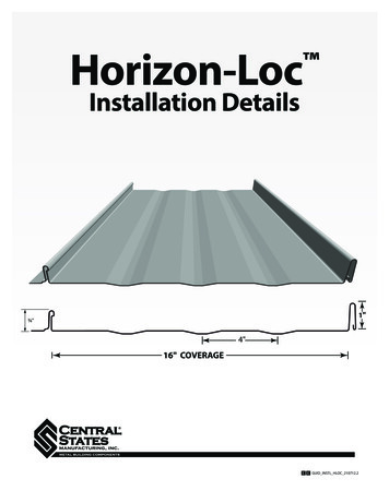
Horizon-Loc Installation Details1"¾"4"16" COVERAGEC E GUID INSTL HLOC 210712 .2
INDEXInformation in the catalog may vary by plant location.Please call your salesperson to verify product availability.Important Information & Safety . . . . . . . . . . . . . . . . . . . . . . . . . . . . . . 3Fastener Spacing . . . . . . . . . . . . . . . . . . . . . . . . . . . . . . . . . . . . . . . . . . . . 4Tool & Equipment . . . . . . . . . . . . . . . . . . . . . . . . . . . . . . . . . . . . . . . . . . . 4Concealed Fastener Tools . . . . . . . . . . . . . . . . . . . . . . . . . . . . . . . . . . . . 4Foot Traffic . . . . . . . . . . . . . . . . . . . . . . . . . . . . . . . . . . . . . . . . . . . . . . . . . . 5Field Cutting . . . . . . . . . . . . . . . . . . . . . . . . . . . . . . . . . . . . . . . . . . . . . . . . 5Roof Preparation Tips . . . . . . . . . . . . . . . . . . . . . . . . . . . . . . . . . . . . . . . . 5Substrate Penetration . . . . . . . . . . . . . . . . . . . . . . . . . . . . . . . . . . . . . . . 6Substructure Condition . . . . . . . . . . . . . . . . . . . . . . . . . . . . . . . . . . . . . . 6Panel Installation Overview . . . . . . . . . . . . . . . . . . . . . . . . . . . . . . . . . . 7Trim Installation Overview . . . . . . . . . . . . . . . . . . . . . . . . . . . . . . . . . . . 7Panel Installation . . . . . . . . . . . . . . . . . . . . . . . . . . . . . . . . . . . . . . . . . . . . 8Eave Termination . . . . . . . . . . . . . . . . . . . . . . . . . . . . . . . . . . . . . . . . . . . . 9Concealed Fastener Conditions . . . . . . . . . . . . . . . . . . . . . . . . . . . . . . 10-23Drip Edge Trim . . . . . . . . . . . . . . . . . . . . . . . . . . . . . . . . . . . . . . . . . 10-11Rake Trim . . . . . . . . . . . . . . . . . . . . . . . . . . . . . . . . . . . . . . . . . . . . . . 12-13Sidewall Trim . . . . . . . . . . . . . . . . . . . . . . . . . . . . . . . . . . . . . . . . . . . 14-15Endwall Trim . . . . . . . . . . . . . . . . . . . . . . . . . . . . . . . . . . . . . . . . . . . 16-17Valley Trim . . . . . . . . . . . . . . . . . . . . . . . . . . . . . . . . . . . . . . . . . . . . . 18-19Transition Trim . . . . . . . . . . . . . . . . . . . . . . . . . . . . . . . . . . . . . . . . . 20-21Ridgecap Trim . . . . . . . . . . . . . . . . . . . . . . . . . . . . . . . . . . . . . . . . . 22-23Exposed Fastener Conditions . . . . . . . . . . . . . . . . . . . . . . . . . . . . . . . . 24-31Eave Trim . . . . . . . . . . . . . . . . . . . . . . . . . . . . . . . . . . . . . . . . . . . . . . 24-25Rake Trim . . . . . . . . . . . . . . . . . . . . . . . . . . . . . . . . . . . . . . . . . . . . . . 26-27Ridge/Hip Trim . . . . . . . . . . . . . . . . . . . . . . . . . . . . . . . . . . . . . . . . . 28-29Valley Trim . . . . . . . . . . . . . . . . . . . . . . . . . . . . . . . . . . . . . . . . . . . . . 30-312C E N T R A L S TAT E S M A N U FA C T U R I N G , I N C .Effective 01/2022 Information subject to change
IMPORTANT INFORMATIONThis manual contains suggestions and guidelines onhow to install Horizon-Loc panels.The drawings in thisguide are for illustration purposes only and may notapply to all building designs or product applications.The installation details shown are proven methodsof construction, but are not intended to cover allinstances, building requirements, designs, or codes.It is the responsibility of the designer/installer toensure that the details meet particular buildingrequirements. The designer/installer must be awareof, and allow for, expansion/contraction of roofpanels. The details may require changes or revisionsdue to each project’s conditions.There are certain minimum live, snow, dead,collateral, and wind loads that a roof must generallybe designed to support. Consult local buildingofficials to determine the appropriate buildingdesign load requirements. A professional engineershould be consulted for all roof system designs. Itis the buyer’s responsibility to verify all applicablecode requirements, check all measurements,and determine suitability of product for the job.The buyer is also responsible for determininglengths and quantities needed. Prior to orderingand installing materials, all dimensions shouldbe verified with field measurements. Impliedwarranties of merchantability and fitness for aparticular purpose are disclaimed. All HorizonLoc instructions assume that a qualified firm orindividual has been contacted regarding applicationof this product. Failure to comply with statedrecommendations relieves the manufacturer ofresponsibility for any damage or deterioration of theproduct incurred and voids any applicable warranty.Central States Manufacturing reserves the right tomodify, without notice, information in this guide.If you have questions regarding proper installationof Horizon-Loc or information not included in thisguide, contact your salesperson.SAFETYEach job site presents different hazards; thereforeit is the responsibility of the buyer/installer todetermine the safest way to install the HorizonLoc roof panel system based on the recommendedinstructions contained in this guide. Provide crewmembers working on the roof with required safetyrailing, netting or safety lines. If you must walk ona metal roof, take great care. Metal panels canbecome slippery, so always wear shoes with nonslip soles. Avoid working on metal roofs during wetconditions when the panels can become extremelyslippery. Walking or standing on a metal roof whichdoes not have a plywood or other deck beneath itis not recommended. However, if you must do so,always walk on the purlins, never between. HorizonLoc is designed to be installed over solid plywooddecking.OSHA safety regulations should be complied withat all times.Always wear heavy gloves when working with steel panels to avoid cuts from sharp edges.When power cutting or drilling steel panels, always wear safety glasses to prevent eyeinjury from flying metal fragments.C E N T R A L S TAT E S M A N U FA C T U R I N G , I N C .Effective 01/2022 Information subject to changeCAUTION3
FASTENER SPACINGMaximum fastener spacing* for 16" wide 26 gaugepanels with wind loads up to 80 mph:DECK THICKNESSSPACING1/2".18" o.c.5/8".21" o.c.3/4".24" o.c.TIPTo follow UL580 testing for aClass 90 rating, fasteners shouldbe spaced at 4.9" on center.*Slot on leg may not coincide with above chart.TOOLS & EQUIPMENT SnipsTape MeasureElectric Metal Shear*Caulking GunCordless DrillBlind Rivet ToolChalk Line6" Hand SeamerHemming/Folding ToolGlovesNotcher*We do not recommend the use of a power circularsaw to cut panels. Use of a power saw could: Increase the instance of edge rust. Cause hot metal shavings on panel surfaceto damage panel finish.We recommend that the installer have priorexperience and knowledge of the listed tools andtheir uses in working with metal roofing.CONCEALED FASTENER TOOLSHand Snips4NotcherRivet HolePunchHand RiveterFoldingToolsC E N T R A L S TAT E S M A N U FA C T U R I N G , I N C .Effective 01/2022 Information subject to change6" HandSeamer
FOOT TRAFFICCare of metal panels and flashings must beexercised throughout installation. Foot traffic cancause distortion of panel and damage to finish.Traffic over the installed system must be kept toan absolute minimum. If continuous foot trafficis necessary for maintenance over certain areasof the roof, then a permanent walkway shouldbe installed. If continuous foot traffic is necessaryduring installation, provide walking platforms toavoid any panel damage, or leave panels off wherethere is easiest access to roof until projects is almostcomplete. Then install panels in this area.When walking on the roof panels is unavoidable,walk only in the flats of the panel. Walking on theribs can cause damage to the panels.All applicable safety regulations, including OSHA regulations, should be complied withduring the panel installation process.CAUTIONFIELD CUTTINGThere are a number of ways to cut sheet metalquickly and accurately. Tin snips or a “nibbler” typeelectric tool are recommended for field cuttingHorizon-Loc panels. Cutting over a trash barrel willhelp catch the tiny metal shavings that the machineproduces.Although Central States discourages it, if a powersaw is used, the blade will generate slivers ofmetal chips. These slivers and metal chips must beimmediately removed from the Horizon-Loc panelsbecause they will damage the finish and shortenthe life of the product. One method of preventingthis problem is to flip the panels over when cutting.This allows the slivers and metal chips to be brushedfrom the back side and avoids damaging the painton the top side of the panels. Make sure that stacksof panels are away from the cutting area so shavingsdo not blow onto other panels.All product surfaces should be free of debris at all times. Installed surfaces should be wiped cleanat the end of each work period. Never cut panels over metal surfaces. When cutting metal panels,always wear heavy gloves to avoid cuts from sharp edges and safety glasses to prevent eye injury.CAUTIONShavings created by saw cutting or drilling may cause the panel to rustand will void warranties in affected areas.ROOF PREPARATIONS TIPS Horizon-Loc is designed to be installed oversolid decking. We recommend a minimum 1/2"plywood sheathing Make sure any existing decking is smooth, leveland in good condition. Replace any deckingnot meeting those requirements. If there is an existing asphalt shingle roof itmust be removed. Make sure the roof is clear of any debris thatmight interfere with installation. Use minimum 30 lb. felt or syntheticunderlayment. Use an alignment or “chalk” line where the firstpanel is installed. Central States recommendsthat this line be vertical and 1/4" from the rakeedge of the roof deck and square with the eave.Other methods of confirming the squarenesscan also be used.C E N T R A L S TAT E S M A N U FA C T U R I N G , I N C .Effective 01/2022 Information subject to change5
SUBSTRATE PENETRATIONIn warm weather and tropical climates, red rosinpaper should be applied over the felt paper toprevent the felt paper from sticking to the panelsand tearing the vapor retarder. The red rosin paperwill allow for better thermal expansion. In coldweather climates, it is recommended that you usean ice and water shield at the valley and eave. Thisneeds to be applied over the substrate before theunderlayment is installed.ROOF SLOPE FACTOR .08331.11801.1180HIP/VALLEYSLOPEROOFSLOPE 60081.64151.64151.68531.68531.73201.7320NOTE: This chart to be used as a quoting guide only. Central States Manufacturing recommends field measuring all lengths before placing an order.NOTE: This chart to be used as a quoting guide only. Central States Manufacturing recommends field measuring all lengths before placing order.(L) x (Hip Valley Multiplier)H Multiplier) H(L) x (Hip Valley(F) x (Slope Factor) S(F) x (Slope Factor) SSUBSTRUCTURE CONDITIONPanel distortion may occur if not applied overproperly aligned and uniform substructure.The installer should check the roof deck forsquareness before installing Horizon-Loc panels.Several methods can be used to verify squarenessof the structure for proper installation of the panels.by measuring diagonally between the two pointsestablished, the dimension should be exactly amodule of five (5) to have a square corner. Multipleuses of this system may be required to determinebuilding squareness. If the endwall cannot be madesquare the roof system cannot be installed as shownin these instructions.Method A – One method for checking the roof forsquareness is to measure diagonally across oneslope of the roof from similar points at the ridge andeave and obtain the same dimension.Method B – The 3-4-5 triangle system may also beused. To use this system, measure a point from thecorner along the edge of the roof at a module ofthree (3). Measure a point from the same corneralong another edge at a module of four (4). Then,6C E N T R A L S TAT E S M A N U FA C T U R I N G , I N C .Effective 01/2022 Information subject to change
PANEL INSTALLATION OVERVIEWFamiliarize yourself with all installation instructionsbefore starting work. Before beginning installation,you should examine the substrate or framing toensure that all supporting members are straight,level, and plumb to avoid any panel distortion.Substructures should be designed to meet allnecessary code requirements.Some field cutting and fitting of panels and trimsis to be expected by the installer and minor fieldcorrections are a part of normal installation work.It is the responsibility of the installer to ensure asuitable substrate prior to the application of HorizonLoc. Underlayment must be nailed or stapleddown. Distortion in the panel caused by an unevensubstrate, ripples, or laps in the vapor barrier, debris,protruding nails and staples, button cap nails, etc.,are not defects in the materials and are not theresponsibility of Central States Manufacturing.All trims, closures, and accessories shown on theinstallation drawings are available from CentralStates Manufacturing unless noted otherwise.Oil canning in the flat area of the panels is commonto the industry and does not affect the integrity ofthe panel. Therefore, oil canning is not a reason forrejection.The panels should be installed plumb, straight, andsquare to the eave. To keep the bottom edge of theroof perfectly straight and even, the panels mustbe installed square to the bottom edge. Begin bychecking the roof for square; if it is square, you maypull the layout marks directly from the edge of therake.If the roof isn’t perfectly square, install the first panelparallel to your square line, making sure that the firstrib does not hang over the gable edge of the roofsheathing. (Any overhang can prevent the gabletrim from fitting tight against the rake.)NOTE: Copper metallic panels must be installedin the same direction! See directional arrows orstickers provided with your metal panel orderduring the panel installation process.TRIM INSTALLATION OVERVIEWOn runs of more than 10' 2" that require more thanone length of trim, overlap the pieces by 2". Thematerial is thin enough that the overlaps are notnoticeable. Trim is attached with rivets or gasketedscrews; take care to drive the screws enough toflatten the neoprene washer but not enough todeflect the roofing or the trim.The tricky part is finishing the ends of each trimrun. It may take a bit more time, but cutting andfolding the ends of the trim will give the roof amore finished look.When hooking the hem, measure over on hem3" from end of trim piece. Cut hem 1/8" up fromthe bend to 3" mark. Cut off back of hem. On lappiece, open up hem with screwdriver. Insert piece.Slide together. Use rivets and sealant on lap whereneeded.Remove strippable film from panels and trims beforeinstallation.Strippable film on Textured panels and trim must be removed within 30 days ofmanufacture date. Strippable that is left on for more than 30 days may be hard to peel offand is not a reason for a refund or replacement from the manufacturer.C E N T R A L S TAT E S M A N U FA C T U R I N G , I N C .Effective 01/2022 Information subject to changeCAUTION7
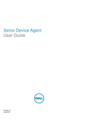
PANEL INSTALLATION1. Align the female edge of the first panel with thechalk line that was snapped at the rake edge. Thisline can be 0" – 1 3/4" from the rake. Panel shouldoverhang eave 1 1/2". See Figure 1.4. Align the second panel female edge with thestarter panel male edge. See Figure 2. Panels mustbe flush to one another. Remember, panels shouldextend over eave trim by 1 1/2".2. Panels should be installed perpendicular to ridgefor ridge trim attachment. Check panel alignment.If panel is properly aligned proceed to step 3.5. Lightly compress and snap panels together atseam. Snap panels from eave to ridge. Screw thesecond panel in place using 1" low profile waferhead screw in the male edge fastening flange.3. Attach rake edge to roof with a 1" paintedneoprene metal to wood fastener spaced at 48"on center. Then fasten the panel along the maleedge fastening flange with 1" low profile waferhead. Special care has to be taken not to overdrivethe screws in the male edge fastening flange.The screw flange is slotted to allow for slightpanel movement during normal expansionand contraction. To avoid panel distortion and toallow for maximum expansion and contraction ofthe panel, the screws should be snugged againstthe flange, but not so snug that the flange deflectsunder the screw head. To allow for movement ofthe panel towards the eave or ridge, place thefastener in the middle of the 5/8" slot. See fastenerspacing on page 4.6. Continue to apply panels as in steps 4 and 5.7. Panels at the eave can be terminated in twoways, with fasteners or without. Each will dependon aesthetic consideration determined by theinstaller or building owner.FIGURE 11" WAFER HEAD SCREW8C E N T R A L S TAT E S M A N U FA C T U R I N G , I N C .Effective 01/2022 Information subject to change
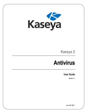
EAVE TERMINATION WITH FASTENERSPanels can be fastened along the eave with a #10 x 1" painted neoprene metal to wood fastener. Use butyltape under the panel. Fasten along a line parallel to the eave edge and 3" up from the eave edge. Thefasteners can be spaced 4" apart in the minor rib striations as shown in Figure 3.1" METAL TO WOOD SCREWHORIZON-LOC BUTYL TAPEFIGURE 3EAVE TERMINATION WITHOUT FASTENERSPanels can also be terminated with a hemming toolto provide a smoother appearance. When using thedrip edge condition to terminate the eave, panelsmustbe ordered 2" longer than your eave length toHORIZON-LOC account for the drip edge lip and the panel’s hem.STEP 1: Create a tab in the panel by cutting a notch in both sides of the panel. Cut through the male and femalelegs/ribs 1" up from panel end. Then cut on inside of major ribs with metal shears. See Figure 4.HORIZON-LOC FIGURE 4STEP 2: Place the hemming tool over the newlycreated tab in the panel as shown in Figure 5.STEP 3: With the hemming tool bend the tab downand under to 180 as shown in Figure 6.HORIZON-LOC FIGURE 5HORIZON-LOC FIGURE 6STEP 4: The panel is then ready to be installed over the Drip Edge trim, using the lip on the Drip Edge trim to securethe panel in place at the eave as shown on page 10.C E N T R A L S TAT E S M A N U FA C T U R I N G , I N C .Effective 01/2022 Information subject to change9
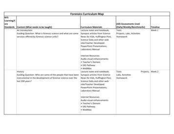
/////////////////////////////////////////CONCEALED FASTENERDRIP EDGE TRIM CONDITION1" WAFER HEAD SCREW(IN FLANGE)HORIZON-LOC 1" WAFER HEAD SCREW(12" ON CENTER)REQUIRED TRIMS:TIPWhen ordering Horizon-Loc panels, be sure to add an extra2" to the length for hemming over the drip edge. (One inchcovers the drip edge and one inch is hemmed under).DRIP EDGE - RDCPaintedsidepitch10C E N T R A L S TAT E S M A N U FA C T U R I N G , I N C .Effective 01/2022 Information subject to change
/////////////////////////////////////////CONCEALED FASTENERDRIP EDGE TRIM CONDITIONHORIZON-LOC FIGURE 1.FIGURE 2.DIRECTIONS:NOTE: See page 9 for detailed information on eave termination without fasteners1. Screw the drip edge to the decking.4. Slide panel over drip edge, snap inpanel, and screw into decking.2. Notch the Horizon-Loc panels atthe rib (1 inch from the end of thepanel).5. Repeat steps 2-4 for each HorizonLoc panel along the drip edge.3. Using the Horizon-Loc foldingtool, fold the panel at the notchingso that theunpainted sides of the1" WAFER HEAD SCREWpanel are(INfacingFLANGE)each other.6. Seal end thoroughly as in Figure1, or leave tab when notching andfold over end for a more finishedlook as in Figure 2.HORIZON-LOC C E N T R A L S TAT E S M A N U FA C T U R I N G , I N C .Effective 01/2022 Information subject to change1" WAFER HEAD SCREW(12" ON CENTER)See page 24 forexposed fastenercondition11
/////////////////////////////////////////CONCEALED FASTENERRAKE TRIM CONDITIONPOP RIVET(2’ O.C.)HORIZON-LOC BUTYL TAPE - BTL(CONTINUOUS)1" WAFER HEAD SCREW(12" ON CENTER)1" WAFER HEAD SCREW(12" ON CENTER)See page 26 forexposed fastenerconditionREQUIRED TRIMS:OPEN HEM RAKE - CFRAZEE CLOSURE - HLZCCLEAT - HLCL11 16"PaintedsidePaintedside11 8"Paintedside11 16"12C E N T R A L S TAT E S M A N U FA C T U R I N G , I N C .Effective 01/2022 Information subject to change
/////////////////////////////////////////CONCEALED FASTENERRAKE TRIM CONDITIONHORIZON-LOC POP RIVET(2’ O.C.)BUTYL TAPE - BTL(CONTINUOUS)DIRECTIONS:1. Install the cleat along the rake ofthe roof and install Horizon-Locpanel on top of the cleat. The edgeof the panel should meet with theedge of the rake. POP RIVET(2’ O.C.)2. Install zee closure on top of thepanel. Use butyl tape beneath toensure proper sealing. Run the zeealong the length of the rake andscrew down to the panel.3. Install the rake trim to the cleat andzee closure by snapping the openhems of the rake trim over thecleat and zee. Pop rivet the rake tothe zee along the joints and every5 feet along the rake. Overlap trimsa minimum of 2" with butyl tapebetween laps.HORIZON-LOC C E N T R A L S TAT E S M A N U FA C T U R I N G , I N C .Effective 01/2022 Information subject to change13
HORIZON-LOC /////////////////////////////////////////CONCEALED FASTENERSIDEWALL TRIM CONDITION1" WAFER HEAD SCREW(12" ON CENTER)POP RIVET(2’ O.C.)HORIZON-LOC BUTYL TAPE - BTL(CONTINUOUS)1" WAFER HEAD SCREW(12" ON CENTER)REQUIRED TRIMS:OPEN HEM SIDEWALL - CFSIPaintedsidepitchZEE CLOSURE - HLZC11 16"Paintedside11 8"11 16"14C E N T R A L S TAT E S M A N U FA C T U R I N G , I N C .Effective 01/2022 Information subject to change
/////////////////////////////////////////CONCEALED FASTENERSIDEWALL TRIM CONDITIONPOP RIVET(2’ O.C.)BUTYL TAPE - BTL(CONTINUOUS)HORIZON-LOC DIRECTIONS:1" WAFER HEAD SCREW(12" ON CENTER)1. Install Horizon-Loc panels up tothe sidewall. Install zee closure ontop of the panel along the sidewallusing butylPOPtapeRIVET to ensure propersealing. (2’ O.C.)3. Repeat steps 1 and 2 for each panelalong the sidewall.4. Install Horizon-Loc panels over thesidewall. Overlap trims a minimumof 2" with butyl tape between laps.2. Slide the open hem of the sidewalltrim over the zee and screwHORIZON-LOC intosidewall. Pop rivet the sidewalltrim to the zee closure.C E N T R A L S TAT E S M A N U FA C T U R I N G , I N C .15Effective 01/2022 Information subject to changeBUTYL TAPE - BTLBUTYL TAPE - BTL
/////////////////////////////////////////CONCEALED FASTENERENDWALL TRIM CONDITION1" WAFER HEAD SCREW(12" ON CENTER)POP RIVET(2’ O.C.)HORIZON-LOC BUTYL TAPE - BTL(CONTINUOUS)1" WAFER HEAD SCREW(2 PER PANEL)REQUIRED TRIMS:OPEN HEM ENDWALL - CFSIZEE CLOSURE - HLZCVented Zee Closure available if needed.Paintedsidepitch11 16"Paintedside11 8"11 16"16C E N T R A L S TAT E S M A N U FA C T U R I N G , I N C .Effective 01/2022 Information subject to change
/////////////////////////////////////////CONCEALED FASTENERENDWALL TRIM CONDITIONPOP RIVET(2’ O.C.)HORIZON-LOC BUTYL TAPE - BTL(CONTINUOUS)DIRECTIONS:1" WAFER HEAD SCREW(12" ON CENTER)1. Install Horizon-Loc panels up tothe endwall. Install zee closure ontop of the panel along the endwallusing butyl tape to ensure propersealing. Zee closures will needto be cut in 15-1/2" lengths andscrewed to the panel. Use a drill athigh rpm to avoid damaging butyltape seal when fastening screws.Seal cut edge of zee closure withtube sealant.2. Slide the open hem of the endwalltrim over the zee and screw intoendwall. Overlap trims a minimumof 2" with butyl tape between laps.Pop rivet the endwall trim to thePOP RIVETzee closure.(2’ O.C.)3. Repeat steps 1 and 2 for each panelalong the endwall.4. Install wall panels over the endwall.HORIZON-LOC C E N T R A L S TAT E S M A N U FA C T U R I N G , I N C .Effective 01/2022 Information subject to change17
/////////////////////////////////////////CONCEALED FASTENERVALLEY TRIM CONDITIONThere are two methods for installing concealed fastener valley. The 1 piece valley can be difficult to lap.The 3 piece valley system can be used if valleys need to be overlapped.1" WAFER HEAD SCREW(IN FLANGE)1" WAFER HEAD SCREW(12" ON CENTER)HORIZON-LOC 1 PIECE VALLEY1" WAFER HEAD SCREW(IN FLANGE)HORIZON-LOC BUTYL TAPE - BTL(CONTINUOUS)VALLEY CLEAT3 PIECE VALLEYSee page 30 forexposed fastenerconditionREQUIRED TRIMS:OPEN HEM VALLEY - CFVTVALLEY -VT1WIDE VALLEY - "14"C E N T R A L S TAT E S M A N U FA C T U R I N G , I N C .Effective 01/2022 Information subject to changeVALLEY CLEAT - HLVCPaintedsidePaintedsides
/////////////////////////////////////////CONCEALED FASTENERVALLEY TRIM CONDITIONTYPICAL PANELEND SEALMITER CUTTO MATCHSLOPE1" WAFER HEAD SCREW(IN FLANGE)DIRECTIONS:1" WAFER HEAD SCREW(12" ON CENTER)HORIZON-LOC HORIZON-LOC (MITER CUTTO MATCHSLOPE)1. Using the folding tool,hemthe3. Hem the panel at a 45 angle (orBUTYL TAPE- BTL slideend of the valley 1 inchandaccording to the valley pitch)(CONTINUOUS)over drip edge (if drip edge iswhere it meets the valley and slidebeing used).under the open hem on the valley.5. Repeat step 3 for each panel as itmeets the valley. Overlap trimsa minimum of 6" with butyl tapebetween laps.2. Install valley to decking, placingscrews as far up as possible on the3-1/8" section of the valley.6. Use tube sealant at panel end.4. Slide panel over valley, snap inpanel, and screw into decking.C E N T R A L S TAT E S M A N U FA C T U R I N G , I N C .Effective 01/2022 Information subject to change1" METAL TO WOOD SCREW(4 PER PANEL)19
BUTYL TAPE - //////CONCEALED FASTENERTRANSITION TRIM CONDITION1" WAFER HEAD SCREW(12" ON CENTER)HORIZON-LOC POP RIVET(2’ O.C.)HORIZON-LOC BUTYL TAPE - BTL(CONTINUOUS)1" WAFER HEAD SCREW(2 PER PANEL)REQUIRED TRIMS:OPEN HEM GAMBREL - CFGAZEE CLOSURE - HLZCPaintedsidepitch11 16"Paintedside11 8"11 16"20C E N T R A L S TAT E S M A N U FA C T U R I N G , I N C .Effective 01/2022 Information subject to change
/////////////////////////////////////////CONCEALED FASTENERTRANSITION TRIM CONDITIONHORIZON-LOC HORIZON-LOC BUTYL TAPE - BTL(CONTINUOUS)1" WAFER HEAD SCREW(12" ON CENTER)HORIZON-LOC DIRECTIONS:1. Install the bottom Horizon-Locpanels and attach zee closures.Zee closures will need to be cutin 15-1/2" lengths and screwed tothe panel. Use butyl tape to ensureproper sealing. Seal cut edge ofzee closure with tube sealant.2. Slide the open hem of gambreltrim over zee, and screw gambrelto upper decking. Overlap trimsa minimum of 2" with butyl tapePOP RIVETbetween laps.(2’ O.C.)3. Notch and hem panel 1" and slideover open hem on gambrel trim.Screw panel to decking.4. Pop rivet trim to zee on lowerportion of the trim.5. Repeat steps 1 through 3 for eachpanel along the transition.HORIZON-LOC C E N T R A L S TAT E S M A N U FA C T U R I N G , I N C .Effective 01/2022 Information subject to change21
/////////////////////////////////////////CONCEALED FASTENERBUTYL TAPE (BTL)(CONTINUOUS)RIDGECAP TRIM CONDITIONHORIZON-LOC BUTYL TAPE (BTL)(CONTINUOUS)POP RIVET(2’ O.C.)HORIZON-LOC 1" WAFER HEAD SCREW(IN FLANGE)1" METAL TO WOOD SCREW(2 PER PANEL)See page 28 forexposed fastenerconditionREQUIRED TRIMS:OPEN HEM RIDGECAPCFRCPaintedsideOPEN HEM WIDE RIDGECAPPaintedCFWRCsideOPEN HEM FLAT RIDGEPaintedCFFRCZEE CLOSURE - HLZCVented Zee Closure available if needed.side11 16"pitchpitchpitchPaintedside11 8"11 16"22C E N T R A L S TAT E S M A N U FA C T U R I N G , I N C .Effective 01/2022 Information subject to change
/////////////////////////////////////////CONCEALED FASTENERRIDGE CAP TRIM CONDITION1" METAL TO WOOD SCREW(2 PER PANEL)POP RIVET(2’ O.C.)BUTYL TAPE (BTL)(CONTINUOUS)HORIZON-LOC DIRECTIONS:1. Install panels on both sides of roofup to the ridge, and install zeeclosures. Zee closures will needto be cut in 15-1/2" lengths andscrewed to the panel. Use butyltape to ensure proper sealing.Seal cut edge of zee closure withtube sealant. When venting, leavea gap for air flow at ridge.BUTYL TAPE (BTL)2. Snapridgecap over zee closures(CONTINUOUS)and pop rivet to the zee every 2’and at joints.POP RIVET(2’ O.C.)When overlapping ridgecap, cut 6" off bottom HORIZON-LOC hem of theunderlapping ridgecap and slide upper ridgecap over. Pop rivet withsealant on each lap. Overlap trims a minimum of 6" with butyl tapeor sealant between laps.1" WAFER HEAD SCREW(IN FLANGE)METALNTOUWOODSCREWC E N T R A L S T A T E S 1"FA CTURING, INC.(2MPERAPANEL)Effective 0
The installation details shown are proven methods of construction, but are not intended to cover all instances, building requirements, designs, or codes . . their uses in working with metal roofing . FASTENER SPACING TOOLS & EQUIPMENT CONCEALED FASTENER TOOLS Hand Snips Notcher Rivet Hole Punch Hand Riveter Folding Tools