Transcription
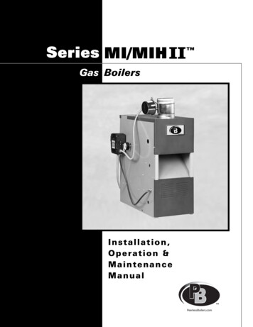
Series MI/MIH II Gas BoilersInstallation,Operation &MaintenanceManual
TABLE OF CONTENTSTABLE OF CONTENTSUSING THIS MANUAL1A. INSTALLATION SEQUENCE . . . . . . . . . . . . .1B. SPECIAL ATTENTION BOXES . . . . . . . . . . . .11. PREINSTALLATION2A. ACCESSIBILITY CLEARANCES . . . . . . . . . . .2B. CLEARANCE FROM COMBUSTIBLECONSTRUCTION . . . . . . . . . . . . . . . . . . . . . .2C. AIR FOR COMBUSTION ANDVENTILATION . . . . . . . . . . . . . . . . . . . . . . . . .3D. INSTALLATION SURVEY . . . . . . . . . . . . . . . .6E. PLANNING THE LAYOUT . . . . . . . . . . . . . . . .62. BOILER SET-UP73. WATER PIPING AND CONTROLS8A. BOILER SUPPLY AND RETURN . . . . . . . . . . .8B. SAFETY RELIEF VALVE . . . . . . . . . . . . . . . . .9C. PIPING FOR ZONED SYSTEMS . . . . . . . . .10D. EXPANSION TANK . . . . . . . . . . . . . . . . . . . .11E. INDIRECT-FIRED WATER HEATER . . . . . . .11F. FREEZE PROTECTION . . . . . . . . . . . . . . . . .114. VENTING12A. INTEGRAL DRAFT HOOD . . . . . . . . . . . . . .12B. VENT DAMPER INSTALLATION –GENERAL . . . . . . . . . . . . . . . . . . . . . . . . . . .12C. VENT PIPING AND CHIMNEY . . . . . . . . . . .13D. BOILER REMOVAL FROM COMMONVENTING SYSTEM . . . . . . . . . . . . . . . . . . .145. GAS PIPING156. ELECTRICAL17A. WIRING . . . . . . . . . . . . . . . . . . . . . . . . . . . . .17B. ZONED SYSTEM WIRING . . . . . . . . . . . . . .17C. CONTROLS . . . . . . . . . . . . . . . . . . . . . . . . . .17D. SEQUENCE OF OPERATION . . . . . . . . . . . .207. START-UP PROCEDURES21A. COMPLETING THE INSTALLATION . . . . . .21B. CONTROL DESCRIPTIONS . . . . . . . . . . . . .24C. ADJUSTMENT OF GAS PRESSUREREGULATOR . . . . . . . . . . . . . . . . . . . . . . . . .24D. CHECKING BURNER INPUT . . . . . . . . . . . . .24E. CHECK-OUT PROCEDURE . . . . . . . . . . . . . .258. TROUBLESHOOTING26A. SHUT-DOWN CAUSED BY PILOT OUTAGE,BLOCKED VENT SHUT-OFF SWITCH ORFLAME ROLL-OUT SAFETY SHUT-OFFSWITCH . . . . . . . . . . . . . . . . . . . . . . . . . . . .26B. TROUBLESHOOTING GUIDES . . . . . . . . . .269. MAINTENANCE29A. GENERAL . . . . . . . . . . . . . . . . . . . . . . . . . . .30B. DAILY (WITH BOILER IN USE) . . . . . . . . . . .30C. WEEKLY (WITH BOILER IN USE) . . . . . . . . .30D. MONTHLY (WITH BOILER IN USE) . . . . . . .30E. ANNUALLY (BEFORE START OF HEATINGSEASON) . . . . . . . . . . . . . . . . . . . . . . . . . . .3010. BOILER DIMENSIONS & RATINGS3211. REPAIR PARTS33A. BASE/COMBUSTIBLE FLOOR PAN . . . . . . .33B. MANIFOLD, GAS VALVE & PILOT . . . . . . . .34C. BLOCK/DRAFT HOOD & JACKET . . . . . . . .36D. CONTROLS/CIRCULATOR/VENT &DAMPER . . . . . . . . . . . . . . . . . . . . . . . . . . . .38
USING THIS MANUALUSING THIS MANUALA. INSTALLATION SEQUENCEFollow the installation instructions provided in thismanual in the order shown. The order of theseinstructions has been set in order to provide the installerwith a logical sequence of steps that will minimizepotential interferences and maximize safety duringboiler installation.B. SPECIAL ATTENTION BOXESThroughout this manual you will see special attentionboxes intended to supplement the instructions and makespecial notice of potential hazards. These categoriesmean, in the judgment of PB Heat, LLC.:DANGERIndicates a condition or hazard which will causesevere personal injury, death or major propertydamage.WARNINGIndicates a condition or hazard which may causesevere personal injury, death or major propertydamage.CAUTIONIndicates a condition or hazard which will or cancause minor personal injury or property damage.NOTICEIndicates special attention is needed, but not directlyrelated to potential personal injury or propertydamage.1
PREINSTALLATION1. PREINSTALLATIONRead carefully, study these instructions before beginning work.This boiler must be installed by a qualified contractor.The boiler warranty can be voided if the boiler is not installed, maintained and serviced correctly.NOTICEThe equipment must be installed in accordance with those installation requirements of the authority havingjurisdiction or, in the absence of such requirements, to the current edition of the National Fuel Gas Code, ANSIZ223.1/NFPA 54 and/or CAN/CSA B149.1, Natural Gas and Propane Installation Code.Where required by the authority having jurisdiction, the installation must conform to American Society ofMechanical Engineers Safety Code for Controls and Safety Devices for Automatically Fired Boilers, ASME CSD-1.IMPORTANTIn accordance with Section 325 (f) (3) of the Energy Policy and Conservation Act, this boiler is equipped with afeature that saves energy by reducing the boiler water temperature as the heating load decreases. This feature isequipped with an override which is provided primarily to permit the use of an external energy managementsystem that serves the same function.THIS OVERRIDE MUST NOT BE USED UNLESS AT LEAST ONE OF THE FOLLOWING CONDITIONS IS TRUE: An external energy management system is installed that reduces the boiler water temperature as theheating load decreases. This boiler is not used for any space heating This boiler is part of a modular or multiple boiler system having a total input of 300,000BTU/hr or greater. This boiler is equipped with a tankless coil.A. ACCESSIBILITY CLEARANCESInstall boiler not less than 24″ (610 mm) between the leftside, top, and front of the boiler and adjacent wall orother appliance, when access is required for servicing.B. CLEARANCE FROM COMBUSTIBLECONSTRUCTIONThe design of this boiler is certified for alcove installationwith the following clearances:1. 6″ (152 mm) between sides and combustibleconstruction.2. 24″ (610 mm) between top of jacket andcombustible construction.3. 6″ (152 mm) between draft hood and combustibleconstruction.4. 6″ (152 mm) between vent pipe and combustibleconstruction.5. 10″ (254 mm) between rear of jacket andcombustible construction.2WARNINGDo not install this boiler on combustible flooringunless it is installed on a special combustible floorpan provided by PB Heat, LLC. Boiler installation oncombustible flooring without the special pan is a firehazard.To order combustible floor pan, use the 5-digit stockcodes listed in Table 11.1 of this manual.WARNINGDo not install this boiler on carpeting. Boilerinstallation on carpeting is a fire hazard. Install thisboiler on non-combustible flooring or use acombustible floor pan to install this boiler on othernon-carpeted flooring.
PREINSTALLATIONC. AIR FOR COMBUSTION ANDVENTILATION1. Adequate combustion air and ventilation air must beprovided for this appliance in accordance with thesection of the National Fuel Gas Code entitled, “Airfor Combustion and Ventilation” or applicableprovisions of the local building code. Subsections 2through 8 as follows are based on the National FuelGas Code requirements.2. Required Combustion Air Volume: The total requiredvolume of indoor air is to be the sum of the requiredvolumes for all appliances located within the space.Rooms communicating directly with the space inwhich the appliances are installed and throughcombustion air openings sized as indicated inSubsection 3 are considered part of the requiredvolume. The required volume of indoor air is to bedetermined by one of two methods.3. Indoor Air Opening Size and Location: Openingsconnecting indoor spaces shall be sized and locatedas follows:a. Combining spaces on the same floor:Provide two permanent openings communicatingwith additional spaces that have a minimum freearea of 1 in2 per 1000 Btu/hr (22 cm2 per 1000 W)of the total input rating of all gas fired equipmentbut not less than 100 in2 (645 cm2). Oneopening is to begin within 12 inches (305 mm)from the top of the space and the other is tobegin within 12 inches (305 mm) from the floor.The minimum dimension of either of theseopenings shall be 3 inches (76 mm). See Figure1.1 for an illustration of this arrangement.a. Standard Method: The minimum requiredvolume of indoor air (room volume) shall be 50cubic feet per 1000 BTU/Hr (4.8 m3/kW). Thismethod is to be used if the air infiltration rate isunknown or if the rate of air infiltration is knownto be greater than 0.6 air changes per hour. Asan option, this method may be used if the airinfiltration rate is known to be between 0.6 and0.4 air changes per hour. If the air infiltration rateis known to be below 0.4 then the Known AirInfiltration Rate Method must be used. If thebuilding in which this appliance is to be installedis unusually tight, PB Heat recommends that theair infiltration rate be determined.b. Known Air Infiltration Rate Method: Wherethe air infiltration rate of a structure is known, theminimum required volume of indoor air forappliances other than fan assisted and for theSeries MI Boiler shall be determined as follows:21 ft3ACH I other Btu 1000 /hr Required Volumeother where:Iother Input of appliances other than fanassisted in Btu/hrACH air change per hour (percent of thevolume of the space exchanged perhour, expressed as a decimal)Figure 1.1: Air Openings – All Air from Indoorson the Same Floorb. Combining spaces on different floors:Provide one or more permanent openingscommunicating with additional spaces that havea total minimum free area of 2 in2 per 1000Btu/hr (44 cm2 per 1000 W) of total input ratingof all equipment. See Figure 1.2 for anillustration of this arrangement.For fan assisted appliances, calculate the requiredvolume of air using the following equation:Ifan15 ft3ACH I fan Btu/1000hr Required Volumefan Input of the fan assisted appliances inBtu/hrNote: These calculations are not to be used forinfiltration rates greater than 0.60 ACH.Figure 1.2: Air Openings – All Air from Indoorson Different Floors3
PREINSTALLATION4. Outdoor Combustion Air: Outdoor combustion air isto be provided through one or two permanentopenings. The minimum dimension of these airopenings is 3 inches (76 mm).a. Two Permanent Opening Method: Providetwo permanent openings. One opening is tobegin within 12 inches (305 mm) of the top ofthe space and the other is to begin within 12inches (305 mm) of the floor. The openings areto communicate directly or by ducts with theoutdoors or with spaces that freely communicatewith the outdoors. The size of the openings shallbe determined as follows:i.ii. Where communicating with the outdoorsthrough horizontal ducts, each opening shallhave a minimum free area of 1 in2 per 2000Btu/hr (22 cm2 per 2000 W) of total ratedinput for all appliances in the space. SeeFigure 1.5.Where communicating directly or throughvertical ducts with the outdoors each openingshall have a minimum free area of 1 in2 per4000 Btu/hr (22 cm2 per 4000 W) of totalinput rating for all equipment in the space.See Figure 1.3 for openings directlycommunicating with the outdoors or Figure1.4 for openings connected by ducts to theoutdoors.Figure 1.5: Air Openings – All Air from Outdoorsthrough Horizontal DuctsFigure 1.3: Air Openings – All Air Directly fromOutdoorsFigure 1.4: Air Openings – All Air from Outdoorsthrough Vertical Ducts4b. One Permanent Opening Method: Provideone permanent opening beginning within 12inches (305 mm) of the top of the space. Theopening shall communicate directly with theoutdoors, communicate through a vertical orhorizontal duct, or communicate with a spacethat freely communicates with the outdoors. Theopening shall have a minimum free area of 1 in2per 3000 Btu/hr of total rated input for allappliances in the space and not less than thesum of the cross-sectional areas of all ventconnectors in the space. The gas-fired equipmentshall have clearances of at least 1 inch (25 mm)from the sides and back and 6 inches (150 mm)from the front of the appliance. See Figure 1.6for this arrangement.Figure 1.6: Air Openings – All Air from Outdoorsthrough One Opening
PREINSTALLATION5. Combination Indoor and Outdoor Combustion Air: Ifthe required volume of indoor air exceeds theavailable indoor air volume, outdoor air openings orducts may be used to supplement the availableindoor air provided:a. The size and location of the indoor openingscomply with Subsection 3.b. The outdoor openings are to be located inaccordance with Subsection 4.c. The size of the outdoor openings are to be sizedas follows: VavailVreq Areq Afull x 1 –where:Areq minimum area of outdoor openings.Afull full size of outdoor openings calculatedin accordance with Subsection 4.Vavail available indoor air volumeVreq required indoor air volume6. Engineered Installations: Engineered combustion airinstallations shall provide an adequate supply ofcombustion, ventilation, and dilution air and shall beapproved by the authority having jurisdiction.ii. Where the free area through a louver or grilleis not known, it shall be assumed that woodenlouvers will have 25% free area and metallouvers and grilles will have 75% free area.iii. Nonmotorized dampers shall be fixed in theopen position.b. Motorized dampers shall be interlocked with theequipment so that they are proven in the fullopen position prior to ignition and duringoperation of the main burner.i.The interlock shall prevent the main burnerfrom igniting if the damper fails to openduring burner startup.ii. The interlock shall shut down the burner ifthe damper closes during burner operation.9. Combustion Air Ductsa. Ducts shall be constructed of galvanized steel oran equivalent corrosion- resistant material.b. Ducts shall terminate in an unobstructed space,allowing free movement of combustion air to theappliances.7. Mechanical Combustion Air Supply:c. Ducts shall serve a single space.a. In installations where all combustion air isprovided by a mechanical air supply system, thecombustion air shall be supplied from theoutdoors at the minimum rate of 0.35 ft3/min per1000 Btu/hr (0.034 m3/min per 1000 W) of thetotal rated input of all appliances in the space.b. In installations where exhaust fans are installed,additional air shall be provided to replace theexhaust air.c. Each of the appliances served shall beinterlocked to the mechanical air supply toprevent main burner operation when themechanical air supply system is not in operation.d. In buildings where the combustion air is providedby the mechanical ventilation system, the systemshall provide the specified combustion air rate inaddition to the required ventilation air.8. Louvers & Grills:a. The required size of openings for combustion,ventilation, and dilution air shall be based on thenet free area of each opening.i.Where the free area through a louver or grilleis known, it shall be used in calculating theopening size required to provide the free areaspecified.d. Ducts shall not serve both upper and lowercombustion air openings where both suchopenings are used. The separation between ductsserving upper and lower combustion airopenings shall be maintained to the source ofcombustion air.e. Ducts shall not be screened where terminating inan attic space.f. Horizontal upper combustion air ducts shall notslope downward toward the source of thecombustion air.g. The remaining space surrounding a chimney liner,gas vent, special gas vent, or plastic piping installedwithin a masonry, metal, or factory built chimneyshall not be used to supply combustion air.h. Combustion air intake openings located on theexterior of buildings shall have the lowest side ofthe combustion air intake opening at least 12inches (305 mm) above grade.WARNINGLiquefied Petroleum (LP) is heavier than air and maycollect or “pool” in a low area in the event of a leakfrom defective equipment. This gas may then ignite,resulting in a fire or explosion.5
PREINSTALLATIOND. INSTALLATION SURVEYFor new and existing installations, a Water InstallationSurvey is available from PB Heat, LLC. The survey willprovide information on how a hot water boiler workswith your specific system and will provide an overviewof hot water system operation in general.You can also use this survey to locate system problemswhich will have to be corrected. To obtain copies of theWater Installation Survey, contact your PB Heatrepresentative or download it from PeerlessBoilers.com.6E. PLANNING THE LAYOUTPrepare sketches and notes of the layout to minimize thepossibility of interferences with new or existingequipment, piping, venting and wiring.
BOILER SET-UP2. BOILER SET-UP1. Provide a sound, level foundation. Locate boiler asnear to the chimney or outside wall as possible andcentralized with respect to the heating system.4. Separate the wood shipping pallet from the boilerbase by removing two (2) hold-down bolts at eachend of the boiler base.2. Locate boiler in front of installation position beforeremoving crate.5. Move boiler into final position. If using combustiblefloor pan, install boiler on pan as outlined in theinstructions included with the pan.3. If using combustible floor pan, position pan onfoundation or flooring.7
WATER PIPING AND CONTROLS3. WATER PIPING AND CONTROLSA. BOILER SUPPLY AND RETURN1. Size the supply and return to suit the system. Atypical piping arrangement is shown in Figure 3.1.Refer also to the I B R Guide - ResidentialHydronic Heating Installation/Design and the PBHeat Water Survey for additional guidance duringwater piping installation.2. Return Piping:Pipe the drain valve to a tee, provided, and the1-1/4 NPT return tapping near the bottom of the leftsection. Pipe the return to the tee. Pipe the drainvalve nipples and tee to the 1-1/4 NPT returntapping as shown in Figure 3.1.Figure 3.1: Supply and Return Piping83. Supply Piping:Pipe the supply to the 1-1/2 NPT supply tapping atthe top and rear of the boiler.4. When system return water temperature will be below130 F (54 C), pipe the boiler with a bypassarrangement to blend the system return and hotsupply to obtain at least 130 F (54 C) entering theboiler. For more information on bypass piping,consult the PB Heat Water Survey.
WATER PIPING AND CONTROLS6. Install this boiler so that the gas ignition systemcomponents are protected from water (dripping,spraying, etc.) during appliance operation andservice (circulator replacement, condensate trap,control replacements, etc.).7. If this boiler and distribution system is used inconjunction with a refrigeration system, pipe thechilled medium in parallel with the boiler and installthe proper valve to prevent the chilled medium fromentering the boiler. A drawing illustrating this hookup is provided in Figure 3.2.8. When the boiler is connected to heating coilslocated in air handling units where they may beexposed to refrigerated air circulation, install flowcontrol valves or other automatic means to preventgravity circulation of the boiler water during thecooling cycle.9. If this boiler is installed above radiation level,provide a low water cutoff device, either as a part ofthe boiler or at the time of boiler installation.Figure 3.2: Parallel Hook-Up with Water ChillerB. SAFETY RELIEF VALVE1. Locate safety relief valve and fittings in bagassembly.2. If air elimination is not required at the safety reliefvalve tapping, install valve and piping as shown inFigure 3.3.3. For air elimination at the safety relief valve tapping,install valve and piping as shown in Figure 3.4.CAUTIONPipe the discharge of safety relief valve to preventinjury in the event of pressure relief. Pipe thedischarge to a drain. Provide piping that is the samesize as the safety relief valve outlet.Figure 3.3: Safety Relief Valve Hook-UpInstallation with Air Elimination inSystem PipingFigure 3.4: Safety Relief Valve Hook-Up withAir Elimination9
WATER PIPING AND CONTROLSC. PIPING FOR ZONED SYSTEMS1. See Figures 3.5 and 3.6 for basic zoned systemlayouts.2. Run each zone pipe down then up to zone toprevent air accumulation in piping.3. If required, provide means to isolate and drain eachzone separately.Figure 3.5: Zone Piping with Zone ValvesFigure 3.6: Zone Piping with Circulators10
WATER PIPING AND CONTROLSD. EXPANSION TANKF.For new or existing systems that must be freezeprotected:1. Consult the tank manufacturer’s instructions forspecific information relating to tank installation. Sizethe expansion tank for the required system volumeand capacity. See Table 10.2 in Section 10 for boilerwater content.2. Expansion tanks are available with built-in fill valvesand check valves for reducing supply water pressureand maintaining minimum system pressure. Checkthe design features of the tank and provide valves asnecessary. Refer back to Figure 3.1 for typicalexpansion tank piping.FREEZE PROTECTIONWARNINGUse only inhibited propylene glycol solutions of up to50% by volume with water. Ethylene glycol is toxicand can attack gaskets and seals used in hydronicsystems.E. INDIRECT-FIRED WATER HEATERIf the boiler is to be used in conjunction with an indirectfired water heater, refer to Figure 3.7 for typical piping.Follow the instructions provided by the water heatermanufacturer. Pipe the water heater as a separate zone.1. Glycol in hydronic applications is speciallyformulated for this purpose. It includes inhibitorswhich prevent the glycol from attacking metallicsystem components. Make certain that the systemfluid is checked for the correct glycol concentrationand inhibitor level.2. The glycol solution should be tested at least once ayear and as recommended by the glycolmanufacturer.3. Glycol solutions expand more than water. Forexample, a 50% by volume solution expands 4.8%in volume for a temperature increase from 32 F(0 C) to 180 F (82 C), while water expands 3% withthe same temperature rise. Allowance must be madefor this expansion in system design.4. For more information, consult the PB Heat WaterInstallation Survey and the glycol manufacturer.Figure 3.7: Typical Piping with Indirect-Fired Water Heater11
VENTING4. VENTINGA. INTEGRAL DRAFT HOOD1. The MI/MIH II boiler is equipped with a built-indraft hood. This device is designed to:a. provide for the ready escape of flue gases fromthe boiler in the event of no draft.b. prevent a backdraft from entering the boiler.B. VENT DAMPER INSTALLATION –GENERAL1. Do not use one vent damper to control two or moreheating appliances. See Figure 4.1.2. Follow these and the installation instructions that areincluded with the vent damper. Observe the cautionsand warnings that accompany all instructions.c. control stack draft during operation.These tasks are accomplished without the extraheight requirements of a separate draft hood.2. The draft hood relief opening is the large rectangularpassage at the front of the boiler. Make certain thatthere are no obstructions to airflow in front of thisopening.3. A vent safety shut-off switch is located within thedraft relief opening to shut off the boiler in case of ablocked vent condition. See Section 7B for detailsregarding this device. See Figure 6.1 in Section 6(Electrical) for spill switch location.4. The vent damper can be mounted directly onto theround draft hood outlet (vent connector) on top ofthe boiler, or in vent piping close to the boiler. Seethe Vent Damper Installation Instructions below.Figure 4.1: Venting Multiple Appliances123. Make certain that minimum clearances provided inthe vent damper manufacturer’s instructions aremaintained and that adequate space is available fordamper access and service.4. Orient the damper operator to facilitate connectionof the harness with the vent damper and boiler. Noteflue gas flow arrow on vent damper and orient asrequired. For installation with damper mounted invertical position, see Figure 4.2. For installation withdamper mounted in horizontal position, mount theunit as shown in Figure 4.3 to avoid excessive heaton the operator or condensation drips into theoperator.
VENTINGC. VENT PIPING AND CHIMNEY1. Install vent piping in accordance with Venting ofEquipment part of the National Fuel Gas Code,ANSI Z223.1/NFPA 54, sections 7.2, 7.3 or 7.4 ofCAN/CSA B149.1, Natural Gas and PropaneInstallation Code, or applicable provisions of thelocal building codes.2. Inspect the existing chimney and lining for structuralsoundness, corrosion and perforations. Repair asnecessary.3. Install vent pipe to slope upward at least 1/4" perlineal foot (21 mm per meter) between the drafthood outlet and the chimney.4. Before connection of joints, inspect the vent pipeinterior for foreign objects such as tools, equipment,rags, etc. and remove if present.5. Insert vent pipe into but not beyond the inside wallof the chimney flue.6. Do not connect vent connectors serving appliancesvented by natural draft into any portion of mechanicaldraft systems operating under positive pressure.7. Support horizontal portions of the venting system toprevent sagging by use of metal strapping orequivalent means. Locate supports at no more than4 foot (1.2 meter) intervals.Installer le tuyau d’évent avec une pente ascendanteminimum de 21 mm au mètre (1/4 po au pied) à lasortie du coupe-tirage et la cheminée.Fournir un support à toute portion horizontale dusystème d’évacuation à l’aide de courroies de métalou une méthode équivalente afin de l’empêcher des’affaisser. Placer les supports à des intervalles nedépassant pas cent vingt deux (122) centimètres(4 po), ou en suivant les recommandations d’installation du fabricant.Figure 4.2: Venting with Vent Damper in Vertical PositionFigure 4.3: Venting with Vent Damper in Horizontal Position13
VENTINGD. BOILER REMOVAL FROM COMMONVENTING SYSTEMAt the time of removal of an existing boiler, follow thesesteps with each appliance remaining connected to thecommon venting system placed in operation, while theother appliances remaining connected to the commonventing system are not in operation:Au moment de retirer une chaudière existante, il estimportant de suivre les étapes suivantes pour chaqueappareil raccordé au système d’évacuation commun quisont en service, alors que les autres appareils demeurantraccordés au système d’évacuation commun ne sont pasen service :a. Seal any unused openings in the common ventingsystem.Sceller toute ouverture du système d’évacuationcommun non utilisée.b. Visually inspect the venting system for proper sizeand horizontal pitch and determine there is noblockage or restriction, leakage, corrosion anad otherdeficiencies which could cause an unsafe condition.Effectuer un contrôle visuel du système d’évacuationpour vérifier la taille et la pente horizontale ets’assurer qu’il n’existe aucun blocage ou obstruction,fuite, corrosion ni tout autre problème pouvantmenacer la sécurité.c. Insofar as is practical, close all building doors andwindows and all doors between the space in whichthe appliances remaining connected to the commonventing system are located and other spaces of thebuilding. Turn on any clothes dryers and anyappliance not connected to common venting system.Turn on any exhaust fans, such as range hoods andbathroom exhausts, so they will operate at maximumspeed. Do not operate a summer exhaust fan. Closefireplace dampers.Dans la mesure du possible, fermer toutes les porteset fenêtres de l’immeuble ainsi que toutes les portesentre l’espace dans lequel les appareils quidemeurent raccordés au système d’évacuationcommun se trouvent et le reste de l’immeuble.Mettre en marche les sécheuses et tout autre appareilnon raccordé au système d’évacuation commun.Mettre en marche tous les ventilateurs aspirant, telsque les hottes de cuisinière et les ventilateurs de sallede bain, en les faisant fonctionner à vitessemaximum. Ne pas faire fonctionner les ventilateursaspirant d’été. Fermer les registres de foyers.14d. Place in operation the appliance being inspected.Follow the lighting instructions. Adjust thermostat soappliance will operate continuously.Mettre en service l’appareil à inspecter. Suivre lesinstructions concernant l’allumage. Régler lethermostat afin que l’appareil fonctionne sans arrêt.e. Test for spillage at the draft hood relief opening after5 minutes of main burner operation. Use the flameof a match or candle, or smoke from a cigarette,cigar, or pipe.Vérifier toute fuite à l’orifice de décharge du coupetirage après que le brûleur ait fonctionné pendant 5minutes. Utiliser la flamme d’une allumette ou d’unechandelle ou encore la fumée d’une cigarette, d’uncigare ou d’une pipe.f. After it has been determined that each applianceremaining connected to the common venting systemproperly vents when tested as outlined above, returndoors, windows, exhaust fans, fireplace dampers andany other gas-burning appliance to their previousconditions of use.Après avoir établi que les résidus de combustion dechaque appareil qui demeure raccordé au systèmecommun sont adéquatement évacués lorsque soumisau test décrit ci-dessus, remettre en place les portes,fenêtres, portes intérieures, ventilateurs aspirants,registres de foyer et appareils fonctionnant au gaz.g. Any improper operation of the common ventingsystem should be corrected so that the installationconforms with the current edition of the NationalFuel Gas Code, ANSI Z223.1/NFPA 54 and/orCAN/CSA B149.1, Natural Gas and PropaneInstallation Code. When resizing any portion of thecommon venting system, the common ventingsystem should be resized to approach the minimumsize as determined using the appropriate tables in theNational Fuel Gas Code, ANSI Z223.1/NFPA 54and/or CAN/CSA B149.1, Natural Gas and PropaneInstallation Code.Tout fonctionnement inadéquat du systèmed’évacuation commun doit être corrigé de manière àrespecter les normes du National Fuel Gas Code,ANSI Z223.1/NFPA 54 et/ou des Codes d’installationCAN/ACG B149. Lorsqu’il est nécessaire de modifierles dimensions de toute portion du systèmed’évacuation commun, ces dernières doivent êtremodifiées de manière à respecter les dimensionsminimums indiquées dans les tableaux du chapitre «Sizing of Category I Venting Systems » du NationalFuel Gas Code, ANSI Z223.1/NFPA 54 ou des Codesd’installation CAN/ACG B149
GAS PIPING5. GAS PIPING1. Size and install the gas supply piping properly inorder to provide a supply of gas sufficient to meetthe maximum demand without undue loss ofpressure between the mete
† An external energy management system is installed that reduces the boiler water temperature as the heating load decreases. † This boiler is not used for any space heating † This boiler is part of a modular or multiple boiler system having a total input of 300,000 BTU/hr or greater. † This boiler is equipped with a tankless coil. IMPORTANT