Transcription
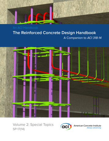
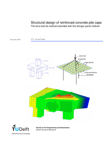
Structural design of reinforced concrete pile capsThe strut-and-tie method extended with the stringer-panel methodDecember 2006A.V. van de Graafcolumn loadstrut elementsstringer elementsshear panel elementsstrut elementFaculty of Civil Engineering and GeosciencesSection Structural Mechanics
A.V. van de GraafStructural design of reinforced concrete pile capsStructural design of reinforced concrete pile capsThe strut-and-tie method extended with the stringer-panel methodA.V. van de GraafDelft, December 2006Delft University of TechnologyFaculty of Civil Engineering and GeosciencesSection Structural Mechanicsi
A.V. van de GraafStructural design of reinforced concrete pile capsPersonaliaSTUDENTAnne Vincent van de Graaf1040626annevandegraaf@yahoo.com 31 (0)6 12 29 61 32GRADUATION COMMITTEEprof.dr.ir. J.G. Rots (supervisor graduation committee)Delft University of TechnologyFaculty of Civil Engineering and Geosciences – Section Structural Mechanicsj.g.rots@bk.tudelft.nl 31 (0)15 278 44 90dr.ir. P.C.J. Hoogenboom (daily supervisor)Delft University of TechnologyFaculty of Civil Engineering and Geosciences – Section Structural Mechanicsp.hoogenboom@citg.tudelft.nl 31 (0)15 278 80 81ir. W.J.M. PeperkampDelft University of TechnologyFaculty of Civil Engineering and Geosciences – Section Concrete Structuresw.peperkamp@citg.tudelft.nl 31 (0)15 278 45 76ir. J.W. WellemanDelft University of TechnologyFaculty of Civil Engineering and Geosciences – Section Structural Mechanicsj.w.welleman@citg.tudelft.nl 31 (0)15 278 48 56ir. L.J.M. Houben (graduation coordinator)Delft University of TechnologyFaculty of Civil Engineering and Geosciences – Section Road & Railway Engineeringl.j.m.houben@tudelft.nl 31 (0)15 278 49 17iii
A.V. van de GraafStructural design of reinforced concrete pile capsPrefaceThis graduation report has been written within the framework of a Master of ScienceProject originally entitled WWW Design of Reinforced Concrete Pile Caps. This projectwas put forward by the Structural Mechanics Section of the Faculty of Civil Engineeringand Geosciences at Delft University of Technology.Although I spent a lot of time in mastering the Java programming language andimplementing the design model in an applet using Java SE Development Kit (JDK) [ 14 ],not much of this work can be found directly in this report. The same applies to the initialwork that I have done in TurboPascal using Borland Delphi [ 13 ]. Therefore, thisgraduation report is rather brief. For those readers, who are interested in using the applet,please refer to the following web address: http://www.mechanics.citg.tudelft.nl/pca.Hereby I would like to thank ir. H.J.A.M. Geers (Faculty of Electrical Engineering,Mathematics and Computer Science at Delft University of Technology) for his adviceduring the design and implementation of the applet. Many thanks also to ir. J.A. den Uijlfor his contribution with Atena 3D. And last but not least, I would like to thank dr.ir.P.C.J. Hoogenboom for his support and suggestions during this project.Delft, December 12, 2006Anne van de Graafv
A.V. van de GraafStructural design of reinforced concrete pile capsTable of contentsPersonalia . iiiPreface . vSummary. ixList of symbols . xi1 Introduction .12 Design problem of the reinforced concrete pile cap . 32.1 Problem description .32.2 Modeling the pile cap.32.3 Research outline.43 Mathematical description of the used elements. 73.1 Co-ordinate systems and notations.73.2 Stringer element .73.3 Shear panel element.103.4 Strut element.143.4.1 Element description .143.4.2 Element rotation.154 Assembling the model and solving the system . 234.1 Assembling the system stiffness matrix .234.2 Processing imposed forces.244.3 Processing tying .244.4 Processing imposed displacements.274.5 Solving the obtained system of linear equations .295 Applet design.315.1 Applet setup and Java basics.315.2 Preprocessor .335.3 Kernel .345.4 Postprocessor .356 Equilibrium considerations. 376.1 Case 1: Symmetrical pile cap consisting of three piles and one column .376.1.1 Equilibrium consideration of the whole structure .386.1.2 Equilibrium consideration of a part of the structure.406.2 Case 2: Asymmetrical pile cap consisting of six piles and two columns .44vii
Structural design of reinforced concrete pile capsA.V. van de Graaf7 Non-linear finite element analysis. 477.1 Geometry of the considered pile cap and material parameters . 477.2 Ultimate load predicted by Pile Cap Applet (PCA). 487.3 Ultimate load predicted by non-linear finite element analysis. 508 Conclusions and recommendations . 57References. 59Appendix A1: Numbering and generating stringer elements. 61Appendix A2: Numbering and generating shear panel elements. 65Appendix A3: Numbering and generating strut elements. 69Appendix B1: Assembling the elements . 73Appendix B2: Generating and processing imposed forces. 79Appendix B3: Generating and processing tying . 81Appendix B4: Generating and processing imposed displacements . 85Appendix B5: Detailed consideration on LU decomposition. 87Appendix C: Matrix and vector classes in Java. 95viii
A.V. van de GraafStructural design of reinforced concrete pile capsSummaryMany foundations in The Netherlands, mainly those in coastal areas, are on piles. Thesepiles are often over 15 m long at distances of 1 to 4 m. If possible, these piles are driveninto the soil at the positions of walls and columns of a building. The presence of piles of aprevious building may hamper a free choice of the new pile positions. Removing the oldpiles is not a solution, because this leaves holes in deep clay layers through which salinegroundwater may penetrate into the upper soil. Moreover, the old piles cannot be reusedbecause their quality cannot be guaranteed. As a consequence, pile caps often have tocover piles that are positioned in an irregular pattern.The objective of this Master of Science Project was to develop a design model forcalculating the pile loading and reinforcement stresses for pile caps on irregularlypositioned foundation piles. This model has been based on the strut-and-tie method,however, the ties have been replaced by another model consisting of stringer elements andshear panel elements. This model predicts vertical pile reactions, reinforcement stressesand shear stresses in concrete. For practical application, it has been implemented in acomputer program called Pile Cap Applet (PCA). This applet was designed to be userfriendly, to require only a moderate amount of data and to execute fast.PCA has been tested and validated in two ways. Firstly, it has been shown that the designmodel meets all equilibrium requirements. This has been tested for two pile caps. Bothcases revealed that the design model complies with horizontal and vertical forceequilibrium and moment equilibrium. From the theory of plasticity it then follows that thismodel gives a safe approximation of the ultimate load. Secondly, the ultimate loadpredicted by PCA has been compared to the ultimate load predicted by a non-linear finiteelement analysis. This comparison yielded several interesting conclusions whereof themost important ones are included in this summary.The ultimate load predicted by PCA is very conservative. Clearly, the real structure cancarry the load in more ways than an equilibrium system (PCA) assumes. Furthermore, forthe considered pile cap the design model predicted another failure mechanism than thefinite element analysis. PCA predicted that the considered pile cap ‘collapsed’ because ofreaching the yield strength in one of the reinforcing bars. In the finite element analysis, thepile cap collapsed because of a shear failure. This failure mechanism cannot be predictedby PCA. For the considered pile cap the vertical pile reactions predicted by PCA areapproximately equal to those predicted by the non-linear finite element analysis. However,the reinforcement stresses at serviceability load according to PCA are much higher thanthose determined by the finite element analysis. This implies that the stresses calculated byPCA are not useful for checking the maximum crack width.ix
A.V. van de GraafStructural design of reinforced concrete pile capsList of symbolsLatin symbolsabcdxdyEcap concreteEcomplE pile concreteErebarEAFGcap concretehNStuilength of a shear panel element [mm]width of a shear panel element [mm]concrete cover [mm]center-to-center distance of reinforcing bars incenter-to-center distance of reinforcing bars inx -direction [mm]y -direction [mm]2Young’s modulus of the cap concrete [N/mm ]complementary energy [Nmm]2Young’s modulus of the pile concrete [N/mm ]2Young’s modulus of the reinforcement [N/mm ]extensional stiffness [N]external force [N]2shear modulus of cap concrete [N/mm ]depth of the pile cap [mm]normal force [N]shear force [N]effective depth of the pile cap with regard to shear stresses [mm]displacement in directioni[mm]Greek symbolsγ xyνστφxφyshear angle [rad]Poisson’s ratio [-]2normal stress [N/mm ]2shear stress [N/mm ]reinforcing bar diameter inreinforcing bar diameter inx -direction [mm]y -direction [mm]Remaining symbolAlength of a stringer element or strut element [mm]xi
A.V. van de Graaf1Structural design of reinforced concrete pile capsIntroductionIt is well-known that many buildings in The Netherlands, mainly those in coastal areas, arefounded on piles. These piles can easily reach a length of over 15 m and are usually spacedat distances of 1 to 4 m. If possible, these piles are driven into the soil at the positions ofwalls and columns. Unfortunately, a structural designer is not always free in this choice,because piles of a previous building may be present. Removing these old piles is not asolution, since this leaves holes in deep clay layers through which saline groundwater maypenetrate into the upper soil. Reusing the old piles is not an option either, because theirquality cannot be guaranteed. These restrictions often result in irregular pile patterns,which makes calculation of pile caps by hand difficult if not impossible.The objective of this Master of Science Project is to develop a design model forcalculating the pile loading and reinforcement stresses for pile caps on irregularlypositioned foundation piles. This design method is based on the strut-and-tie methodextended with the stringer-panel method. The model is implemented in an applet and canbe used for structural design.The composition of this report is as follows. Chapter 2 gives a problem definition,discusses the model constitution and outlines the research. Chapter 3 considers themathematical description of stringer elements, shear panel elements and strut elements.These are used as building blocks for the design model. In Chapter 4 it is explained howto assemble the system starting from the mathematical element descriptions given in theprevious chapter. Furthermore, this chapter includes processing the boundary conditionsand solving the obtained system of linear equations. Chapter 5 discusses the design of theapplet and three important procedures, namely the preprocessor, the kernel and thepostprocessor. In Chapter 6 the Java implementation is tested by checking equilibriumrequirements in two specific cases. Chapter 7 compares the ultimate load predicted by theapplet with a non-linear finite element analysis. Finally, Chapter 8 presents the conclusionsand recommendations.1
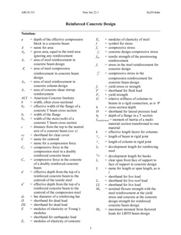
A.V. van de Graaf2Structural design of reinforced concrete pile capsDesign problem of the reinforced concrete pile capThis chapter defines the design problem that was introduced in Chapter 1. Section 2.1gives a description of the problem to be solved. Section 2.2 explains which elements areused and how these elements constitute the pile cap model. Section 2.3 gives an outline ofthe research area including aspects that are not taken into account. In the next chapter,Chapter 3, the elements which constitute the model presented in this chapter aremathematically described.2.1Problem descriptionThe problem to be solved is to develop a designmodel for determining the pile loading and thereinforcement stresses for pile caps on irregularlypositioned foundation piles in buildings (Figure 1).One way of calculating pile caps is to create a modelin a 3D finite element package. An importantdisadvantage of this approach is that it is timeconsuming. Creating the computer model as well asperforming an advanced calculation requires a lot of Figure 1 Example pile captime. Another method for solving this problem is to use rough models, which may becalculated by hand. But since these rough models introduce a lot of uncertainty, a largesafety factor is required. Clearly, structural designers need a reliable and rationalcalculation method, which can be carried out easily.2.2Modeling the pile capFor stocky structures loaded by concentrated forces, thestrut-and-tie method is commonly adopted [ 10 ]. Thismethod uses solely compression members (struts) andtension members (ties). In Figure 2 a strut-and-tie modelhas been drawn for the example pile cap given in Figure 1.Compression members have been drawn in green andFigure 2 Strut-and-tie model fortension members have been drawn in red. If reinforcingthe example pile cap of Figure 1bars are put in the directions of the ties the result wouldbe very impractical to make. Moreover, if a pile cap consists of more piles and columnsthe reinforcement patterns would be even more complicated and therefore labor-intensiveand prone to error. Orthogonal reinforcement patterns with fixed center-to-centerdistances are far more practical. But then, the above mentioned strut-and-tie method isnot convenient anymore. Therefore, the ties are replaced by another model (Figure 3),consisting of stringer elements and shear panel elements ([ 1 ], [ 2 ]). In this renewedmodel, the stringer elements represent the reinforcing bars, while the shear panel elements3
Structural design of reinforced concrete pile capsA.V. van de Graafrepresent the concrete in between. From Figure 3 it can be seen that the load is carried bystrut elements that are hold in place by a combination of stringer elements and shear panelelements.2.3Research outlineSome restrictions need to beintroduced to arrive at apractical design model.column loadstrut elementsstringer elementsThe first restriction is thatcolumns can only transfershear panel elementsnormal (vertical) loads. Astrut elementcolumn load is represented bya concentrated force, which isapplied at the center of gravityof the column (Figure 3).Figure 3 Strut-and-tie model extended with a stringer-panel modelTherefore, moments in thecolumns cannot be included. Horizontal loads and bending moments are excluded fromthis research. Since the piles are modeled as strut elements, they can only transfer normalloads. Furthermore, it is assumed that the tip of the pile is restrained in all directions. Thebehavior of the soil in which the piles are embedded is not taken into consideration, whichalso means that no pile-soil interaction is taken into account. For the axial stiffness of thestringer elements, only the extensional stiffness of the reinforcing bars is taken intoaccount. This means it is assumed that the concrete does not contribute to the transfer oftensile forces and that effects like tension-stiffening are not taken into consideration. Onlymain reinforcement is considered, which means that shear reinforcement and other kindsof reinforcement are excluded from the model. In both directions, only one layer ofreinforcing bars is taken into account. Another restriction is that the dead weight of thepile cap is not taken into consideration. This is acceptable since the dead weight of the pilecap is only a fraction of the load that is carries.The implementation of the design model in an applet also posesa few restrictions. To ensure an orderly Graphical User Interface(GUI) it is decided to limit the maximum number of columns tofour and the maximum number of piles to six. The minimumnumber of piles is set to three to ensure a kinematicaldeterminate system. The center-to-center distances of thereinforcing bars are equal per direction. Only one reinforcing bardiameter can be specified per direction.4Figure 4 Pier on a pile cap
A.V. van de GraafStructural design of reinforced concrete pile capsThe design problem discussed in this graduation report is mainly aimed at pile caps usedin buildings. But the general nature of the design model to be discussed makes itsapplication also suitable for use in for example piers on pile caps (Figure 4).5
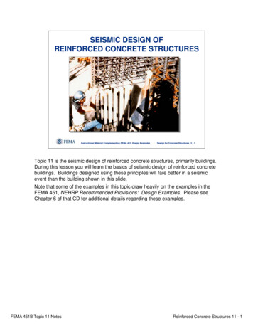
A.V. van de Graaf3Structural design of reinforced concrete pile capsMathematical description of the used elementsIn Chapter 2 it was explained that the model which represents the pile cap consists ofthree different elements, namely stringer elements, shear panel elements and strutelements. This chapter describes the structural behavior of these elements in amathematical way. First, Section 3.1 gives the general agreements concerning local andglobal co-ordinate systems and notations. Then, in Section 3.2, the stiffness relation for astringer element is derived, based on the graduation work of Hoogenboom (1993) [ 6 ]. InSection 3.3 the stiffness relation for a shear panel element is derived using the work ofBlaauwendraad (2004) [ 4 ]. Finally, in Section 3.4 a description of the strut element isgiven, which has been based on the work of Nijenhuis (1973) [ 8 ] and Hartsuijker (2000)[ 5 ]. In the next chapter, Chapter 4, these descriptions are used to formulate the structuralbehavior of the pile cap.3.1Co-ordinate systems and notationsThe global co-ordinate system xyz for the pile capyis indicated in Figure 5. In the next sections, localxco-ordinate systems xyz are defined. In the case ofstringer elements and shear panel elements, thezorientation of the local co-ordinate axes is in thesame direction as the global co-ordinate system(Figure 5). This implies that for these elements arotation matrix is not needed. Because strutelements have a three dimensional orientationFigure 5 Global co-ordinate system(Figure 3) and their local co-ordinate system ischosen according to the orientation of the element, a rotation matrix is necessary.Therefore, Section 3.4 is divided in two subsections. Subsection 3.4.1 gives themathematical description of the strut element. In subsection 3.4.2 the rotation matrix isderived. In the next sections, the following (common) convention is used: scalars are notunderlined, vectors are underlined and matrices are doubly underlined. The derivations inthis chapter are valid for single elements only. To be formally correct a superscript( e ) should be used, but for the sake of convenience this superscript is left out.3.2Stringer elementThe stringer element consists of a bar with length A and extensional stiffness EA andpossesses three degrees of freedom (DOF): u x 1 , u x 2 and u x 3 (Figure 6). The DOF at theends of the element are called u x 1 and u x 3 respectively. The intermediate DOF is namedu x 2 . The element is loaded by two concentrated forces at the ends of the bar, which arecalled Fx 1 and Fx 3 , and an evenly distributed shear force τ t along the bar axis. Thisdistributed shear force is a result of interaction with adjacent shear panel elements, which7
Structural design of reinforced concrete pile capsA.V. van de Graafare described in Section 3.3. The sum of the distributed shear force over the length A isequal to Fx 2 .EAτtFx 1ux1Fx 3ux 3ux 2Ax 0xx AN2N1N (x )Figure 6 Stringer element in a local co-ordinate system xyz [figure taken from Hoogenboom [ 6 ]]The normal force N ( x ) in the bar can be described byN ( x ) N1 x( N1 N 2 ) .A(1)From equilibrium of the bar ends (Figure 7) it may be concluded thatFx 1 N1 and Fx 3 N 2 .(2)Fx 2 can be expressed asFx 2 N1 N 2 τ t A τ t Fx 1N1 N 2.A(3)τtτtN1N2ΔxFx 3Δxlim ( Fx 1 N1 τ t Δx ) Fx 1 N1 0lim ( N 2 Fx 3 τ t Δx ) N 2 Fx 3 0Δx 0Δx 0Figure 7 Equilibrium consideration of the end parts of the stringer elementThe stiffness relation for the stringer element is derived using complementary energy. Theexpression for the complementary energy of the bar reads [ 6 ]AEcompl x 0A12N2dx Fx 1u x 1 Fx 3u x 3 τ tu x ( x ) dx .EAx 0Substitution of equations ( 1 ), ( 2 ) and ( 3 ) in the expression for the complementaryenergy ( 4 ) gives8(4)
A.V. van de GraafStructural design of reinforced concrete pile capsAN1 N 2 N1 N 21 x 0 2 EA N1 x A dx N1ux1 N 2ux 3 x 0 A ux ( x ) dx .AEcompl 2(5)The intermediate DOF u x 2 is now defined as [ 6 ]Aux 2 2u x ( x )dx ,A x 0(6)which may be interpreted as the mean displacement of the stringer element. Furtherelaboration of expression ( 5 ) using equation ( 6 ) leads to2 N12 N1 N 21 22 N1 N 2 Nxx2 dx N1u x 1 N 2 u x 3 ( N1 N 2 ) u x 21 x 0 2 EA AA AEcompl A2N 2 N1 N 2 2 1 3 N1 N 2 1 2 x 3x N1 x 1 N1u x 1 N 2 u x 3 N1u x 2 N 2 u x 22 EA AA x 01 N12 A ( N12 N1 N 2 )A 13 A( N12 2 N1 N 2 N 22 ) N1u x 1 N 2 u x 3 N1u x 2 N 2 u x 22 EA 1 1 N1 N 2 A 13 N12 A 13 N 22 A N1u x 1 N 2 u x 3 N1u x 2 N 2 u x 2 2 EA 3A N12 N1 N 2 N 22 N1u x 1 N 2 u x 3 N1u x 2 N 2 u x 2 . 6 EA The complementary energy should be stationary in relation to variations of the stresses,meaning that the derivatives with respect to N1 and N 2 need to be equal to zero [ 6 ] Ecompl N1 Ecompl N 2 A( 2 N1 N 2 ) ux1 u x 2 0,6 EA A( N1 2 N 2 ) u x 3 ux 2 0.6 EAIn matrix notation these equations read ux1 A 2 1 N1 1 1 0 ux 2 ,6 EA 1 2 N 2 0 1 1 u x 3 (7)where the dot implies matrix multiplication.Pre-multiplication of equation ( 7 ) by the inverse of the left hand side matrix of equation( 7 ), gives ux1 EA 4 2 A 2 1 N1 EA 4 2 1 1 0 ux 2 A 2 4 6 EA 1 2 N 2 A 2 4 0 1 1 u x 3 9
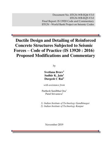
Structural design of reinforced concrete pile capsA.V. van de Graaf ux1 1 0 N1 N1 EA 4 6 2 A 2 6 4 u x 2 . 0 1 N 2 N 2 u x3 (8)From equations ( 2 ) and ( 3 ) it follows that the relation between the internal forces N1and N 2 and external loads Fx 1 , Fx 2 and Fx 3 can be described by Fx 1 1 0 F 1 1 N1 . x2 N Fx 3 0 1 2 (9)The final step in the derivation of the stiffness relation for a stringer element, is tosubstitute equation ( 8 ) into equation ( 9 ), which leads to Fx 1 1 0 ux1 4 6 2 u x 1 F 1 1 EA 4 6 2 u EA 6 12 6 u . x2 A 2 6 4 x 2 x2 A u Fx 3 0 1 264 x3 u x 3 As explained in Section 3.1, a rotation matrix is not needed. So the above relation alsoholds for the global co-ordinate system and reads Fx1 4 6 2 u x1 F EA 6 12 6 u . x2 x2 A Fx 3 2 6 4 u x 3 ( 10 )As stated in Section 2.3, for the axial stiffness of the stringer elements, only theextensional stiffness of the reinforcing bars is taken into account. Therefore, theextensional stiffness EA in equation ( 10 ) can be calculated from the Young’s modulus ofthe reinforcement Erebar and the cross-sectional area of a reinforcing bar. The length A inequation ( 10 ) is equal to the length or width of the adjacent shear panel element.Generating the stringer elements in the applet and the global numbering of the stringerelement DOF is explained in Appendix A1. Once the displacements u x 1 , u x 2 and u x 3 areknown, the normal forces N1 and N 2 acting at the ends of the stringer element can becalculated by using equation ( 8 ).3.3Shear panel elementA shear panel element is a rectangular element that is meant for transmitting an evenlydistributed shear force τ t (Figure 8). At its edges this shear stress interacts with adjacentstringer elements. A shear panel element has a length a , a width b and an effective deptht . Determining this effective depth is explained at the end of this section. The shearpanel element possesses a shear stiffness Gcap concrete , which can be calculated from thewell-known expression10
A.V. van de GraafStructural design of reinforced concrete pile capsGcap concrete Ecap concrete2 (1 ν ),where Ecap concrete represents the Young’s modulus of the cap concrete and ν representsPoisson’s ratio.Fx1ux1Fy1τtFy2xτtu y1τtbyu y2ux2Fx2τtaFigure 8 Shear panel element in a local co-ordinate systemxyzSince the shear stress τ t is constant, the shear angle γ xy will also be constant. Moreover,the edges of the deformed shear panel element remain straight and do not elongate.Therefore, the deformation of the shear panel element can be described by four DOF:u x 1 , u x 2 , u y1 and u y 2 , which are chosen halfway each edge.The resulting shear forces along the edges can be calculated asFx 1 τ ta and Fx 2 τ ta ,( 11 )Fy 1 τ tb and Fy 2 τ tb .From the constitutive relation it is known thatτ t Gtγ xy .( 12 )The shear angle γ xy can be determined from Figure 9γ xy Δu x Δu y u x 2 u x 1 u y 2 u y 1. baba( 13 )aΔu ybΔu xFigure 9 Deformed shear panel elementSubstitution of equation ( 13 ) into equation ( 12 ) gives11
Structural design of reinforced concrete pile capsA.V. van de Graaf u x 2 u x 1 u y 2 u y1 .baa bτ t Gt ( 14 )Substitution of equation ( 14 ) into equations ( 11 ) yields the following stiffness relationu y 2 u y1 uu u x 2 a u x 1a u y 2 u y1 ,Fx 1 Gta x 2 x 1 Gt bbaabb u y 2 u y1 uu u x 2 a u x 1a u y 2 u y1 ,Fx 2 Gta x 2 x 1 Gt baa b b bu y 2 u y1 u y 2 b u y1b u u Fy 1 Gtb x 2 x 1 Gt u x 2 u x 1 ,baa aa b ( 15 )u y 2 u y1 u y 2 b u y1b u uFy 2 Gtb x 2 x 1 Gt u x 2 u x 1 .baa aa b For convenience, the following dimensionless parameters are definedα aband β α 1 .ba( 16 )By using the dimensionless parameters α and β from ( 16 ) and by writing equations( 15 ) in matrix form, the element stiffness relation is obtained Fx 1 α α F x 2 Gt α α Fy 1 1 1 Fy 2 1 11 1β β 1 u x 1 1 u x 2 . β u y1 β u y 2 As explained in Section 3.1, a rotation matrix is not needed. Therefore, the above relationalso holds
Many foundations in The Netherlands, mainly those in coastal areas, are on piles. These piles are often over 15 m long at distances of 1 to 4 m. If possible, these piles are driven into the soil at the positions of walls and columns of a building. The presence of piles of a previous building may hamper a free choice of the new pile positions.