Transcription
Section5INTRODUCTION TOLAND NAVIGATIONKey Points1234Understanding AzimuthsConverting AzimuthsDetermining ElevationCalculating Distance on a MapTactics andTechniques Track
Introduction to Land Navigation 199IntroductionTo accomplish your mission, you must be in the right place at the right time. Being inthe right place requires you to navigate well. Knowing how to read a map is onething—knowing how to use a map to navigate requires that you understand how touse azimuths, elevation, and map distance.In the previous section, you learned how to identify and interpret topographicsymbols, colors, contour lines, and marginal information found on a military map. Youalso learned about the military grid reference system and how to plot grid coordinatesusing a military map and protractor.This section will expand your map-reading skills and introduce you to how themilitary navigates using a map, compass, and protractor. You will learn what anazimuth is and how to convert azimuths in order to navigate using a compass andmap. You will also learn how to determine the elevation of the terrain by analyzing thecontour lines and contour interval data from the marginal information on a militarymap. Lastly, you will learn to compute straight-line and road distance using the scale inthe margin of the military map. Coupled with your learning from your orienteeringand map reading lessons, you will have the basic knowledge to navigate from onepoint to another and arrive safely at your destination.In the following vignette, COL John Zierdt Jr., commander of the 1st SupportCommand during the first Gulf War, remembers how a group of Soldiers paid a seriousprice when they decided to rely on familiarity rather than put into practice basic mapreading and land-navigation skill required of all Soldiers.Captured During Desert StormThe driver had been on a particular route two or three times and thought heknew where he was going. Then instead of turning left, he kept going straight.They even saw the water on their right, which was a dead giveaway that theywere going north rather than west. There were two HETs [heavy trucks] followingeach other. The guy, the one that was eventually captured, was in the leadvehicle, and stopped. And the guys behind him said, “You’re going the wrongway and we need to turn around.” He said, “I am not.” He says, “I’m goingstraight. You can follow me or turn around if you want.”So, they kept going straight. The next thing you knew they were in the middleof a firefight. The second vehicle got turned around in time [and] got out ofthere; the [first] vehicle got stuck and didn’t get turned around, and the two ofDepartment of the Army, XVIII Airborne Corps andUS Army Center of Military HistoryTactics andTechniques Trackthem got captured.
200 SECTION 5eCritical ThinkingIf the drivers of the two vehicles had looked at and oriented their maps, whatmight have told them they were headed in the wrong direction?What would you have done if you were in the second vehicle? Would youhave continued to follow the first vehicle after you decided it was going thewrong way?What could you have said over the radio to the Soldiers in the first vehicle thatmay have triggered in their minds that they were, in fact, going in the wrongdirection?Understanding Azimuthsazimuththe horizontal angle,measured clockwise bydegrees or mils betweena reference directionand the line to anobserved or designatedpoint—there are threebase (reference)directions or azimuths:true, grid, and magneticazimuthThe terms azimuth anddirection areinterchangeable.grid azimuththe angle between gridnorth and a line drawnon the mapEverything in land navigation begins with an azimuth. An azimuth is a horizontal anglemeasured clockwise by degrees or mils between a reference direction and a line to anobserved or designated point. There are three base directions or azimuths: true, grid, andmagnetic.The Army uses azimuths to express direction. Direction is determined from yourstart point, or where you are, outward toward your desired destination, or your intendedtarget. Because you use north (0 or 360 degrees) as your base line, 270 degrees away fromnorth will always be due west.Think of yourself as standing in the middle of a Nebraska cornfield. You are facingnorth. The horizon stretches around you in a great 360-degree circle. If you travel anazimuth of zero degrees—or 360 degrees—or due north—you will wind up in Canada.If you turn to your right and travel on an azimuth of 90 degrees—due east—you willwind up in the Atlantic Ocean, probably off the coast of New Jersey.An azimuth of 180 degrees—due south—will take you into Mexico, and an azimuthof 270 degrees—due west—will take you to the Pacific, just off the coast of NorthernCalifornia.Determining a Grid Azimuth Using a ProtractorThere are two ways you can determine an azimuth. You can use a map to determine agrid azimuth, or you can use a compass to determine a magnetic azimuth. Regardless ofthe technique, you will learn in this chapter how to convert a grid azimuth to a magneticazimuth and a magnetic azimuth to a grid azimuth. You will first use a map and learnhow to determine a grid azimuth. The steps in this process should be very familiar if youhave ever taken a geometry class.To begin, select a start point on the map. Mark it as point A. Identify an end point onyour map. Mark it as point B. Using the edge of your protractor, draw a straight pencilline between points A and B. The line is your azimuth. Now you must determine the gridazimuth of that line—the angle between the line and grid north.When you lay your protractor down on your map, make sure you place it right sideup; verify this by checking to see that the writing on the protractor is not backward. If yourprotractor is wrong side up, you will get grid azimuths that are 180 degrees off from the
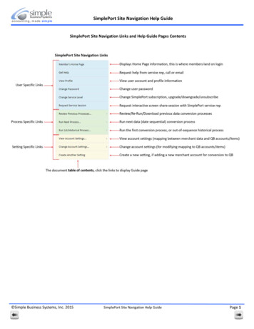
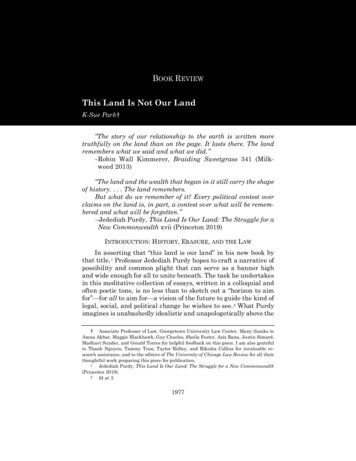
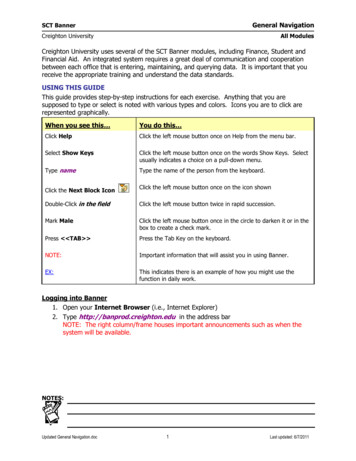
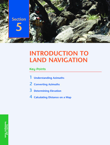
Introduction to Land Navigation 201Although having themils scale on the outsideof the protractor mayseem confusing now,don’t get into the habitof cutting the mils scaleoff your protractor. Laterin your military career,your militaryoccupational specialty(MOS) may require youto state azimuths inmils as well as degrees.Figure 5.1 Army Protractor (GTA 5-2-12, 1981)correct grid azimuth. Also, make sure the 0- or 360-degree mark of your protractor istoward the top (or north) of your map, and make sure the 90-degree mark is toward theright (or east) of your map. If you place your protractor down incorrectly on your map, thegrid azimuth that you determine will be a minimum of 90 degrees off and as much as 270degrees off the actual azimuth.Follow these three steps to determine your grid azimuth from the arbitrary points Aand B (Figure 5.2):1. Place the index of your protractor (the place where the etched vertical line andthe etched horizontal line meet) at the point where the line you drew on yourmap crosses a vertical, north-south grid line.2. Keeping the index at this point, line up the 0-to-180-degree line, or base line, ofthe protractor on the vertical, north-south grid line.3. Follow your line outward to the degree scale of your protractor. Read the valueof the angle from the protractor. This is your grid azimuth from point A to pointB expressed in degrees.Next, you will plot an azimuth from a known point on a map. Imagine you receive anorder to move from your current position in a given direction. Plotting the azimuth onyour map will allow you to see the terrain and objects you will need to navigate throughalong the entire length of your azimuth. The steps are as follows:
202 SECTION 5Figure 5.2 Measuring an Azimuth1. Place your protractor on the map with the index mark at the center of theknown point and the base line parallel to a vertical, north-south grid line.This is the same methodyou will use todetermine the gridazimuth between anytwo points on the map.2. Using your pencil, make a small tick mark on the map at the edge of theprotractor at the desired azimuth. Remember that your protractor will havedegrees on the inner scale and mils on the outer scale. Ensure the tick mark onthe map is beside the desired azimuth in degrees and not mils.3. Lift and reposition the protractor so you can use its side as a straightedge. Drawa line connecting the known point and the tick mark on the map. This is yourgrid direction line—your azimuth.
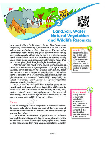
Introduction to Land Navigation 203Determining a Back AzimuthA back azimuth is simply the opposite direction to your azimuth. A simple example iswhen you get on the interstate going north when you wanted to go south. At the nextexit, you get off the interstate, turn around, and get back on the interstate going south. Youjust took a back azimuth, or in slang, you just “did a 180.”To compute a back azimuth from an azimuth, simply add or subtract 180 degrees toor from your original azimuth. Remember that a circle has 360 degrees, so if your azimuthis greater than 180 degrees, adding 180 degrees to determine your back azimuth will giveyou an azimuth that is more than 360 degrees. For example, if your azimuth were 200degrees, adding 180 degrees would result in a back azimuth of 380 degrees, whereassubtracting 180 degrees would result in a back azimuth of 20 degrees. The back azimuth380 degrees is obviously greater than the number of degrees in a circle—20 degrees greater.Sure, you could subtract 360 degrees from 380 degrees and still get the same correct backazimuth of 20 degrees. But this simply adds another step to the process. So, subtracting180 degrees from azimuths greater than 180 degrees simplifies determining back azimuths.Determining a Magnetic Azimuth to an ObjectA magnetic azimuth is an azimuth determined using magnetic instruments, such as acompass. The Army uses two types of compasses: the M2 compass and the lensatic compass.Soldiers use the M2 compass primarily for positioning indirect fire weapons such as mortars.The lensatic compass, pictured in Figure 5.3, is the compass the Army uses for landnavigation.To determine a magnetic azimuth using a compass:1. Open your compass to its fullest so the cover forms a straightedge with the base.Move the lens (the rear sight) to the rearmost position. This allows the dial tofloat freely.2. Place your thumb through the thumb loop, form a steady base with your thirdand fourth fingers, and extend your index finger along the side of the compass.3. Place the thumb of your other hand between the lens (rear sight) and the bezelring; extend your index finger along the remaining side of the compass, and yourremaining fingers around the fingers of your other hand. Tuck your elbows intoyour sides. This will place the compass between your chin and your belt.4. Turn your body toward the object that you wish to get an azimuth to, pointingyour compass cover directly at the object.5. Look down and read the azimuth from beneath the fixed black index line on thecompass face.eCritical Thinking1. Why is it important for you to understand how to determine a back azimuth?2. When would you use a back azimuth?back azimuththe opposite direction ofan azimuth—to obtaina back azimuth from anazimuth, add 180degrees if the azimuth is180 degrees or less, orsubtract 180 degrees ifthe azimuth is 180degrees or more
204 SECTION 5Figure 5.3 Centerhold Technique With aLensatic CompassFigure 5.4 True, Magnetic, and Grid NorthShooting an Azimuth with a CompassWhen you already know the magnetic azimuth that you want to navigate along, you followthe above steps, but reverse steps 4 and 5. You look down at the compass bezel and slowlyturn your body until you see the azimuth you wish to take. Once you see your azimuth onthe bezel, look up, and identify an easily recognizable object off in the distance that is in linewith your azimuth. Once you have identified the object on your azimuth, you can putyour compass away and move to that object. As long as you continue to move to youridentified object, you will be on your desired azimuth. This method is known as “shootingan azimuth.”Converting Azimuthsdeclination diagramthe chart in the maplegend that tells you thedifferences in anglebetween true north, gridnorth, and magneticnorthTwo problems complicate your easy use of a map and compass:First, the surface of the earth is curved, while the surface of your map is flat. This createsproblems between what your map shows as north (grid north) and what really is north(true north).Second, the earth’s magnetic pole is not the same as the earth’s axis. This creates adifference between what your compass shows as north (magnetic north) and what reallyis north (true north).Your map contains information to help you overcome these problems. The declinationdiagram in your map’s legend gives you the information you need to compensate for thedifferences—declination—between grid north, true north, and magnetic north.The declination diagram (Figure 5.4) shows you the difference in angle between anyof these norths. Since you will navigate with a magnetic compass and a grid map, yourprimary concern is the difference between grid north and magnetic north. The differencebetween grid north and magnetic north is known as the G-M angle (grid-magnetic angle).
Introduction to Land NavigationFigure 5.5 Map Declination DiagramThe G-M angle will be shown in the declination diagram and will be expressed indegrees. The G-M angle will either be to the west of grid north (westerly G-M angle) orto the east of grid north (easterly G-M angle). To reduce the confusion of converting easterlyand westerly G-M angles from grid to magnetic or magnetic to grid, the mapmakers nowinclude easy-to-understand instructions on the declination diagram so you can quicklyconvert azimuths without remembering formulas (Figure 5.5).The three vectors that make up the declination diagram (true north, grid north, andmagnetic north) are not drawn to scale. Use the written value for the G-M angle and donot try to measure the vectors to determine the G-M angle.Most military maps will display the declination diagram in the lower margin. Somemaps may not display the declination diagram and will only list the declination informationas a note in the map margin.Adjusting for the Grid-Magnetic (G-M) AngleThe G-M angle value is the size of the angle between grid north and magnetic north. Youwill see it as an arc, indicated by a dashed line, connecting the grid-north and magneticnorth vectors.The G-M angle is important because if you don’t adjust for the G-M angle, your gridazimuth translated from your map to your compass will be wrong by the size of the angleand vice versa. For example, if your G-M angle is 8 degrees and you don’t adjust for thatangle, your grid or magnetic azimuth will be off by 8 degrees. The farther you move awayfrom your start point on your incorrect azimuth, the farther off you will be from yourobjective. The angular error increases the farther you move. Not using the G-M angle whenconverting from a grid azimuth to a magnetic azimuth can cause you to miss your objective.Likewise, if you forget to use the G-M angle when you convert a magnetic azimuth to agrid azimuth, you will plot the wrong azimuth on your map. This could result in passingon incorrect information or calling in inaccurate indirect fire missions.Look at the notes that accompany the G-M angle diagram (Figure 5.5). One note tellsyou how to convert your magnetic azimuth to a grid azimuth; another tells you how toconvert your grid azimuth to a magnetic azimuth. 205
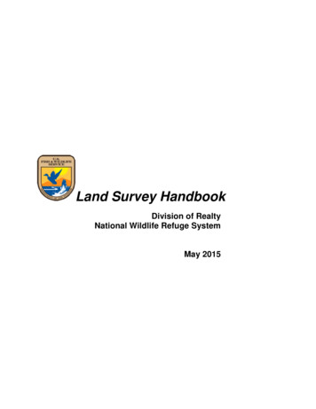
206 SECTION 5A typical note may read “To convert a magnetic azimuth to grid azimuth, subtractG-M angle.” If you have a magnetic azimuth of 270 degrees, and the G-M angle is 8 degrees,your grid azimuth will be 262 degrees.The conversion (whether to add or subtract) depends on whether your map has aneasterly or westerly G-M angle. If your magnetic north is to the right (east) of the gridnorth, then your map has an easterly G-M angle. If your magnetic north is to the left (west)of the grid north, then your map has a westerly G-M angle.You will learn more about azimuths and land navigation as you progress throughROTC. By the end of your MSL III year, you must master land navigation in order to succeedat the Leader Development and Assessment Course (LDAC), which you will attend atFort Lewis, Wash., after your MSL III year.Determining ElevationYou can determine the elevation of any location on your map without any special equipmentusing two things on your map that you learned about in the previous Map Readingsection—contour lines and the contour interval. Before you can determine the elevationof any point on your map, you must first know the contour interval for the map you areusing. As you read previously, you can find the contour interval in the margin of yourmap—usually in the middle of the lower margin. Recall that the contour interval is ameasurement of the vertical distance between adjacent contour lines.Refer to Figure 5.7 to learn how to determine the specific elevation of a point ona map:1. Identify the contour interval and the unit of measure used (feet, meters, oryards) from your map’s marginal information at Figure 5.6 (most military mapsuse meters).Using the map example at Figure 5.7, if you wanted to determine the elevationto point A, you would find the numbered index contour line nearest point A. InFigure 5.7, the closest numbered contour line to point A is the 500-metercontour interval.Determine if point A is above (higher in elevation) the 500-meter contour line,or if point A is below (lower in elevation) than the 500-meter line. Since point Alies between the 500-meter contour line and the 600-meter contour line, movingfrom the closest contour line (500-meter) to point A would be traveling uphill toa higher elevation.2. Determine the elevation of point A by starting at the index contour linenumbered 500 and counting the number of intermediate contour lines (theunmarked contour lines) to point A.Point A is on the second intermediate contour line above the 500-meter indexcontour line. Since the contour interval is 20 meters (Figure 5.6), eachintermediate contour line crossed to get to point A adds 20 meters to the 500meter index contour line. The elevation of point A is 540 meters.3. Determine the elevation of point B by going to the nearest index contour line. Inthis case, it is the upper index contour line, numbered 600. Point B is located on theintermediate contour line immediately below the 600-meter index contour line.Therefore, point B is located at an elevation of 580 meters. Remember, if you areincreasing elevation, add the contour interval to the nearest index contour line.If you are decreasing elevation, subtract the contour interval from the nearestindex contour line.
Introduction to Land NavigationFigure 5.6 Example of a Contour Interval NoteFigure 5.7 Points on Contour LineseCritical ThinkingWhy is it important for you to know how to determine elevation on a militarymap? Think about the azimuth you will plot on your map in order to travel frompoint A to point B. How will knowing elevation help you when navigating frompoint A to point B? Can knowing the elevation help you decide which azimuthsor routes to take to your destination? 207
208 SECTION 54. Estimate the elevation of the hilltop, point C, by adding one-half of the contourinterval to the elevation of the last contour line. In this example, the last contourline before the hilltop is an index contour line numbered 600. Add one-half thecontour interval, 10 meters, to the index contour line. The elevation of thehilltop would be 610 meters. You use the same process to estimate the elevationof a depression, except you subtract half of the contour interval to estimate theelevation at the bottom of the depression.Calculating Distance on a MapNow you know how to plot and determine azimuths on your map, and you understandhow to determine elevation on your map or along your plotted azimuth. But how far is itfrom your start point to your destination? The marginal information on your map allowsyou to determine both straight-line distance and road distance. You can use the graphicscale—located in the lower center portion of the map margin—as a ruler to convertdistances on the map to distances on the ground (Figure 5.8).The graphic scale is divided into two parts. To the right of the zero, the scale is markedin full units of measure and is called the primary scale. To the left of the zero, the scale isdivided into tenths and is called the extension scale.Most maps have three or more graphic scales, each with a different unit of measure,such as meters, yards, statute miles, and nautical miles. When you use the graphic scale,be sure that you use the appropriate unit of measure.Straight-Line DistanceTo calculate the straight-line distance between two points on your map:1. Lay a straight-edged piece of paper on the map so the edge of your papertouches both points and extends past them.2. Make a tick mark on the edge of the paper at each point (Figure 5.9).3. Then move your paper to the graphic bar scale, and use the scale to measure thedistance between the two points. Note that you should align the tick mark on theright with a printed number in the primary scale so that the left tick mark fallswithin the extension scale (Figure 5.10).Figure 5.8 Using a Graphic (Bar) Scale
Introduction to Land NavigationFigure 5.9 Transferring Map Distance to Paper StripFigure 5.10 Measuring Straight-Line Map Distance 209
210 SECTION 5Curved-Line DistanceThe more tick marksyou make whenmeasuring your curvedroute, the moreaccurate your finaldistance will be. This isespecially true whenmeasuring along curves.To measure the distance along a curved route, such as a road, trail, waterway, or othercurved line:Put a straight-edged piece of paper on your map with the edge next to your startingpoint. Place a tick mark on the paper and on your map.Line up the straight edge of the paper with the straight portion of the curved routeyou are measuring. Make a tick mark on both map and paper when the edge of the paperleaves the straight portion of the line you’re measuring. (See View A in Figure 5.11.)Pivot the paper until another straight portion of the curved line lines up with theedge of the paper. Continue in this manner until you have completed the distance youwant to measure. (See View B in Figure 5.11. Notice the number of small ticks on the edgeof the paper and that the last is labeled tick mark B.)Move the paper to the graphic scale to determine the ground distance. The only tickmarks you need to measure are tick marks A and B. (See View C in Figure 5.11.)In order to maintain accuracy when measuring curved distance, it is important to keepthe straight edge of your paper on the same side of the curve you are measuring. If youstart off measuring a curved road on one side of that road, then keep your paper on thatside of the road and mark all of your tick marks on that same side of the road. Do not crossover and start making tick marks on the opposite side of the road.
Introduction to Land NavigationFigure 5.11 Measuring a Curved Line 211
212 SECTION 5eCONCLUSIONYou are a Cadet now. In the not-too-distant future, you may be an Army secondlieutenant leading a platoon. Perhaps, in the distant future, you will be alieutenant colonel commanding a battalion, a colonel commanding a brigade, oreven a major general commanding a division. Whatever your position and rank,you will always need to get your Soldiers from one point to another. If you can’tdo so, you endanger your mission and perhaps the lives of your Soldiers.It’s impossible to overemphasize the importance of map reading and landnavigation. They are critical leadership skills. They are also perishable skills—theyrequire constant practice and review, regardless of a Soldier’s rank or experience.Start now to develop your expertise and work to keep your skills honed and atthe ready.Learning Assessment1. What is an azimuth?2. Explain how to determine a grid azimuth.3. Explain how to determine a magnetic azimuth.4. Explain the differences between the three norths.5. Explain how to use the G-M angle to convert grid and magnetic azimuth.6. What is a contour interval?7. Explain how to determine elevation on a map.8. Explain how to measure the straight line and curved distance between twopoints on a map.
Introduction to Land NavigationKey Wordsazimuthgrid azimuthback azimuthdeclination diagramReferencesField Manual 3-21.8, The Infantry Rifle Platoon and Squad. 28 March 2007.Field Manual 3-25.26, Map Reading and Land Navigation. 18 January 2005.Department of the Army, XVIII Airborne Corps and US Army Center of MilitaryHistory. (10 June 1991). Operations Desert Shield and Desert Storm. Oral HistoryInterview DSIT AE 108. Fort Bragg, NC, and Washington, DC. Retrieved 8 July 2005from 108.htm 213
Determining a Back Azimuth A back azimuthis simply the opposite direction to your azimuth.A simple example is when you get on the interstate going north when you wanted to go south. At the next exit,you get off the interstate,turn around,and get back on the interstate going south.You