Transcription
Modeling Power Electronics inDymola 5Nick BenavidesUniversity of IllinoisUrbana-Champaign
Outline Dymola/Modelica overviewInterface and basic operationText based model exampleComponent creationHalf wave rectifier exampleControlled 2-output flyback converter
Modelica/Dymola Modelica is the underlying modeling language used inthe Dymola Software package The Modelica language allows differential equationmodels to be built without state form, from which stateequations are derived automatically Dymola allows Modelica models to carry a graphicalform, and also provides integration algorithms for usewith the models http://www.modelica.org/ http://www.dynasim.de/
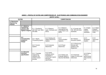
Modeling InterfaceDymola Modeling Interface
Modeling Window Library Tree– Selects active Model– Components can be dragged into active Model’sDiagram Icon– Graphic used when placing in other models Diagram– Graphical Internal Model Modelica Text– Contains all information about Icon, Diagram,– and Documentation when text is expanded
Transorb Icon
Transorb Diagram
Transorb Text
Dymola Simulation Interface
Experiment Setup (General)
Experiment Setup (Output)
Modelica.Electrical.Analog.Interface.Pin Annotation (Graphical Attributes) Removedconnector PinReal v;flow Real i ;end Pin;
M.Electrical.Analog.Interface.OnePort Annotation (Graphical Attributes) Removedpartial model OnePortReal v ;Real I;Pin p;Pin n;equationv p.v - n.v;0 p.i n.i;i p.i;end OnePort;
NbLib.Switches.DiodeCVmodel s.OnePort;parameter Real Goff 1e-5;parameter Real Ron 1e-5;parameter Real Von 0.5;parameter Real Ion Von*Goff ;Boolean off(start true);protectedReal s "Auxiliary variable";equationoff s 0;v - Von s*(if off then 1else Ron);i - Ion s*(if off then Goffelse 1);end DiodeCV;
Starting a Package Return to Modeling interface Select File- New - Package Enter name “DymolaTutorial” and leave all otherentries blank. Check Save Package as single file and click OK Now double click the new package in the LibraryTree and click save to save the new file
Starting a Model Right-click on package DymolaTutorial and selectEdit- New Class in Package- new Model. Enter Name “BouncingBall” and be sure that themodel is inserted in package “DymolaTutorial” To begin editing the BouncingBall, double click onthe model in the Library Tree Enter Text Modeling mode
Bouncing Ball Simulation (1)model BouncingBallReal x(unit "m");Real y(unit "m");Real dx(unit "m/s", start 3);Real dy(unit "m/s", start 10);parameter Real g(unit "m/s 2") 9.8;parameter Real c 0.9 "Coefficienctof elasticity";
Bouncing Ball Simulation (2)equationder(x) dx;der(dx) 0;der(y) dy;der(dy) -g;when (y) 0 thenreinit(dy, -c*dy);end when;end BouncingBall;
Bouncing Ball (3) Integration Options:–Start Time: 0–Stop Time: 20–Intervals: 5000 Click store in model. Now try Plotting some variables such as y byclicking on them in the Variable list Also try right clicking on x and selectingindependent variable as x, then click on y to ploty(x)
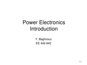
Half Wave Rectifier Circuit (1)
Half Wave Rectifier Circuit (2) Components ��Modelica.Electrical.Analog.Sources.SineVoltage V 170 Freq 60Hz–Modelica.Electrical.Analog.Basic.Inductor L 10e-3 H–Modelica.Electrical.Analog.Basic.Capacitor C 10e-6 F–Modelica.Electrical.Analog.Basic.Resistor R 1 ohm–NB Lib.Switches.Diode CV Ron 1e-5, Goff 1e-5, Von 0.8
Half Wave Rectifier Circuit (3) Integration Options:–Start Time: 0–Stop Time: 0.2–Intervals: 5000–Algorithm: Dassl Click store in model.
Half Wave Rectifier Circuit (4)
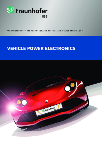
Controlled 2 Output FB (1)
Controlled 2 Output FB (2) Components ge V 48–Modelica.Electrical.Analog.Basic.Capacitor C1 500e-6 F, C2 500e-6 F–Modelica.Electrical.Analog.Basic.Resistor R 10 ohm, R2 2 nsor–Modelica.Blocks.Sources.Constant K 5
Controlled 2 Output FB (3) Components Needed (cont):–NB Lib.Passive.Transformer 3wind L11 180e-6, L12 112e-6, L13 41e-6, L22 73e-6, L23 25.5e-6, L33 9.77e-6–NB Lib.Switches.SwitchIdeal Ron 1e-5, Goff 1e-5, Vth 0.0001–NB Lib.Switches.Diode CV Ron 1e-5, Goff 1e-5, Von 0.8–NB Lib.Controllers.PWM Controller F 75e3 Hz, Von 1–NB Lib.Controllers.PI Controller kp 0.1, ki 50, LowLim 0.05, HighLim 0.95, non-inv (1)
Controlled 2 Output FB (4)
Modelica/Dymola Modelica is the underlying modeling language used in the Dymola Software package The Modelica language allows differential equation models to be built without state form, from which state equations are derived automatically Dymola allows Modelica models to carry a graphical