Transcription
Intelligent GSMAuto-dial Alarm SystemUser’s ManualProfileFor a better understanding of this product, please read this usermanual thoroughly before using it.
CONTENTS[Function Instruction][Control Panel Introduction][Door Contact][PIR Detector][Initialization][Voice Recording][Monitor Panel Power][Connect Outdoor Siren][Monitor GSM Signal][Function Settings]1. Pair Remote Controls2. Pair Wireless Sensors3. Command Chart[Operation Instructions]1. Arm/ disarm Operation2. Emergency Help3. Alarming4. Remote Control[Technical Parameters][Components List][Care and Maintenance]2
[Function Instruction]96 wireless and 3 wired defense zones; each could be programmedindependently and the alarm SMS is editable;Maximum 99 remote controls; both IC 2262 and EV 1527 compatible;Control panel tamper alarm;Sensor low-power alarm, and sensor tamper alarm; it will send SMS whenalarming;English voice prompt for all operations;5 groups alarm phone number and 5 SMS number;One relay link to arm or disarm; one relay support remote control;External power failure/ recovery alert;System settings could be finished by SMS or call DTMF;Built-in RF transmitter: easy to set with wireless sirens;10-second voice recording: will be heard when receiving alarm call;[Control Panel Introduction]In order to make the main panel get the wireless signal well for all wirelessaccessories, please put the alarm host at the central place of your defense area.Make sure it’s away from large metal objects and household appliances whichmay cause high frequency interference, as well as barriers such as reinforcedconcrete wall or fire door, etc.3
LED indicator:LEDLED StatusSystem working statusPOWEROFFNo powerON (red)Power supply is normalFlashing slowly in redPowered by built-in batteryFlashChecking GSM networkSTATUSpersecondand(orange)SIM cardON (orange)GSM network or SIM card isabnormalON (green)FlashperDisarm statussecondAway arm status(green)Flash every 2 secondsHome arm statusON (red)AlarmingFlash per second (red)Delay alarmingFlash quickly in redUnder remote control4
MON/SPKONMonitor/ intercom statusRECONRecordingFlash quicklyRecord replayingONRemoteRFcontroller/wirelesssensor paringZONEONWireless sensor paringOUT2OFFRelay P2 is disconnectedON (red)Relay P2 is connectedOFFRelay P1 is disconnectedON (red)Relay P1 is connectedOUT1Alarm panel built-in buzzer:Buzzer StatusSystem working statusShort beepParing completedOne short beepSystem armLongbeepforGSM network checked successful; receiving correct500msSMSTwo short beepsSystem disarmFour short beepsRepeat paringVoice PromptCorrespondent Operationsystem armedAway arm/ home armsystem disarmedDisarmcoding completedRemote controls or wireless sensors paringplease enter passwordPrompt for remote control operation5
wrong passwordWhen you input a wrong passworddelete completedDeletion is successful.setting completedThe setting is correct.please enter instructionAfter correct passwordBack panel:Wired terminal block:6
1SPK Positive of siren (red cable)2SPK-Negative of siren (black cable)3LB Positive of speaker (red cable)4LB-Negative of speaker (black cable)5P1This switch will be connected when arming; anddisconnected when disarming.67P2Use command to set it connected/ disconnected.Please refer to the “command chart” part on page 989Z1Wired sensor 1 (zone number: 97)10Z2Wired sensor 2 (zone number: 98)11Z3Wired sensor 3 (zone number: 99)12GNDGround7
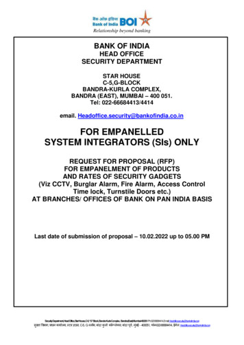
Note:1.Please pay attention to the siren connection. Positive side to “SPK ”and negative to “SPK-”. Do not mix the two cables together whenconnecting. Otherwise, it will damage the transistor in the main panel.2.Wired sensor connection: connect one cable of the wired sensor to GNDand the other to “Z1, Z2 or Z3”.3.Relay P1 will be connected when system armed, and the OUT1 indicatorwill be on. It will be disconnected when system disarmed, and theOUT1 indicator will be off.[Door Contact]Door sensors are used for detecting the status of open and close of windowsand doors. It will detect it and send the signal to main panel.Tear apart the double-side adhesive tape on the magnet and thetransmitter. Then adhere them to the appropriate position.Magnet shouldbe near to thesideoftransmitter withindicator.twoTheshouldalign with eachother and thedistance should not exceed 10mm.Please plug out the antenna for better signal.If the low-power indicator is on, please change the battery.8
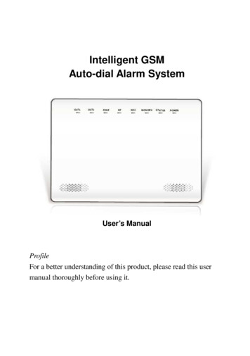
[PIR Detector]PIR detectors are used to detect the movement within a certain range.Fixtheadjustmentbracket on thewallwiththeprovided screwsandattachthedetector to the bracket. It is recommended to mount it at a height of2-2.2m above the floor.Effect of the PIR detection is best when the detection direction is in 90 angle with the walking direction of the intruder. Choose the mostsuitable installation place and angle according to actual situation andtaking the following installation diagram as reference to ensure thedetection effect is best.Please do not fix it under direct sunlight or other strong lights and alsokeep it away from places with frequent strong air stream.If the low-power indicator is on, please change the battery.[Initialization]-Please insert SIM card. Make sure the card has enough balance to make calland send sms.-Connect the siren, wired sensors, or relay-Plug in power adaptor, and turn on the power switch. The POWER indicatorwill be on and the STATUS LED flashes in orange. The system startschecking the GSM network.9
-After checking the SIM card and GSM network normally, the panel willmake a long beep and the STATUS LED will turn green. At this time, thesystem enters into disarm status.If the GSM network is not checked successfully, the STATUS LED will be inorange.-Pair the extra wireless sensors and remote controllers that are not included inthe standard pack, and make function settings.[Voice Recording]In disarm status, press the “REC” button at the back side of the panel. RECindicator at the front panel will turn on. You can start recording now. 10seconds later, it will exit recording and play the recorded voice automatically.At the same time, the REC light will flash quickly. After playing record, youcan press REC button again to re-record.[Monitor Panel Power]This system has the function of SMS alert for external power failure andrecovery. When the external power is cut off, the built-in LI battery will keepthe system working.The SMS content for external power disconnection: Power charger off;power recovery: Power charger on.[Connect Outdoor Siren]The alarm panel has built-in transmitter which can work together withwireless sirens. You need not to connect external transmitters.Setting method:-turn on the Wireless Transmission function (check the command chart onpage 12);-make the siren into coding status (check the siren manual);-make the control panel into disarm status, and then press the SOS button onthe remote control. The panel will send signal to the siren. The siren will makea beep sound after successfully receiving which means setting completed.-siren: exit coding status.10
[Monitor GSM Signal]This system has the function of alert for bad GSM signal. When the GSMsignal is less than 10, the panel will send SMS “bad GSM signal”. And whenthe signal is equal to 0, the siren will start ringing for 5 minutes.The factory default for this function is off, you can turn it on by“password#17#0#” (check the command chart on page 10).[Function Settings]1. Pair Remote ControlsExtra remote controls have to be set with the control panel in order toperform normally. The one in the standard package has been paired.This alarm system supports maximum 99 remote controls.Find the RF button next to the SIM card slot. Press it during disarm status.The RF LED turns on and then press any button on the remote control. Youwill hear a beep sound which means setting is successful. Then press the RFbutton again to save the setting. If the panel makes four short beeps, it meansthe remote control has been paired before or the remote control numberexceeds 99.2. Pair Wireless SensorsWireless detectors have to be set with the control panel in order to trigger italarm. The wireless PIR sensor and door contact in the standard packagehave been paired.This alarm system has 96 wireless defense zones.Press the RF button twice during disarm status. The RF LED and ZONE LEDboth turn on. At this time, trigger the sensor you want to set. You will hear abeep sound which means setting is successful. Then press the RF button againto save the setting. If the panel makes four short beeps, it means the sensor hasbeen paired before or the sensor number exceeds 96.The serial number of the remote controls and sensors is defined by the settingsequence. That means, the first remote control set is NO.1, and the third11
sensor set is in NO.3 zone.3. Command ChartFor all the settings of this alarm system, you can finish by sending SMS ormaking call to the control panel. The SMS content: password#commandDefault password: 123456Alarm receiving: after receiving alarm call, you can do the settings directlywithout inputting password.CommandFunction1#1#Away arm1#2#Home arm1#0#Disarm11#1#Siren on when alarm (default)11#0#Siren off when alarm12#1#Send SMS when alarm (default)12#0#No SMS when alarm15#1#Make call when alarm (default)15#0#No call when alarm17#1#17#0#GSM signal monitor activatedGSM signal monitor deactivated(default)Turn on the siren immediatelyTurn off the sirenInquire the system statusChangepassword(default:123456)Inquire GSM signal (0 31)Inquire IMEI code hodCall or SMS12AlarmreceivingYESNOYESCallSMSCall or SMSSMSNO
#1#40#0#41#xxxx#42#1#42#0#43#1#Set the siren ring time (default: Call or SMS3min; xx: 0 15min)Delete all settings except sensorsand remote controlsDelete sensorsDelete remote controlsDefense zone type setting. AA: defense zonenumber (01 99);B: zone type (1: 24 hours; 2: real-time; 3: delay;4: bypass.);C: home arm setting (0: deactivate, 1: activate);after activation, in home arm status, when thesensor in this zone is triggered, it will triggeralarm.Default: all defense zones are real time, homearm deactivated.Call and SMS setting both ok.Alarm SMS setting. AA: defense SMSzone number (01 99); xx: SMScontent(maximum16characters)Turn off listen-inCallTurn on listen-inTurn on Wireless TransmissionCall or SMSTurn off Wireless Transmission(default)WirelessSirenCodingEncryption (xxxx: 0000 9999;default: FFFF)Turn on SMS reply function(default)Turn off SMS reply functionTurn on arm/disarm SMS13YESNO
61#X#notificationTurn off arm/disarm SMSnotification (default)Arm/ exit delay time setting(00 99seconds, default: 0)Disarm/ entry delay time setting(00 99seconds, default: 0)Turn on arm/ disarm voicepromptTurn off arm/ disarm voiceprompt (default)Turn on all voice promptTurn off all voice prompt(default)Turn on the panel buzzer(default)Turn off the panel buzzerInquire alarm phone numbersSet alarm phone number (1st) X:maximum 15 numbersSet alarm phone number (2nd)Set alarm phone number (3rd)Set alarm phone number (4th)Set alarm phone number (5th)Delete alarm phone number (1st)Delete alarm phone number(2nd)Delete alarm phone number (3rd)Delete alarm phone number (4th)Delete alarm phone number (5th)Inquire alarm SMS numbersSet alarm SMS number (1st) X:maximum 15 numbers14SMSCall or SMSSMSCall or SMS
62#X#63#X#64#X#65#X#61##62##Set alarm SMS number (2nd)Set alarm SMS number (3rd)Set alarm SMS number (4th)Set alarm SMS number (5th)Delete alarm phone number (1st)Delete alarm phone number(2nd)Delete alarm phone number (3rd)Delete alarm phone number (4th)Delete alarm phone number (5th)Turn on the siren for arm/disarmoperationTurn off the siren for arm/disarmoperation (default)Turn on two-way intercomCall94#1#Turn off two-way(default)Connect relay P2Call or SMS94#0#Disconnect relay P295#1#Set zone 97 as NO95#0#Set zone 97 as NC (default)96#1#Set zone 98 as NO96#0#Set zone 98 as NC (default)97#1#Set zone 99 as NO97#0#Set zone 99 as NC 46##98#1#YESintercomNOFactory reset (all settings aredeleted and all the sensors andremote controls are deleted)Turn on tamper alarm function15
98#0#99##99#xx#Turn off tamper alarm function(default)Delete the common SMS content(check explanation in “Note”)Set common SMS. xx: SMScontent(maximum30characters)SMSNote:* Common SMS content: after this setting, all the alarm SMS will start withthis content you set. For example, “99#Tom#”, you may receive alarmmessage like this “Tom 1 Zone Alarm!”. System default for this is empty.*Factory reset: you can also do it like this: keep pressing the “REC” buttonand “RF” button at the same time for 5 seconds. You will hear 6 beeps.* For the above settings, if you set by SMS, you will receive a message fromthe system for confirmation. This function could be set as off if you do notneed the confirmation SMS (42#0#). But for the following settings, SMSreply could not be set off:1. Inquiry setting: Inquire the system status, inquire GSM signal, inquireIMEI, alarm telephone number and SMS number.2. Arm/ disarm the system by SMS.* SMS setting is easily affected by GSM network which may cause delay, soit’s recommended to do the settings by call.* Please make your mobile phone as English version when you send SMS.Please check all the SMS reply in the following table.CommandSMS Reply16
1#1#System armed1#2#Home armed1#0#System disarmed11#1#Siren when alarming enabled11#0#Siren when alarming disabled12#1#Alarm SMS Enabled12#0#Alarm SMS Disabled15#1#Alarm Phone Call Enabled15#0#Alarm Phone Call Disabled17#1#GSM Signal Monitor Enabled17#0#GSM Signal Monitor DisabledSystem armed30##Home armedSystem disarmed31#password#Password set to: 6-digit numbers32##GSM Signal: (01 31)33##IMEI: (15-digit)35#xx#Siren ringing time set to: xx minutes36#0#All settings except coding informationdeleted36#1#All defense zone deleted36#2#All remote controls deleted17
38#AA#B#C#AA: 01-99; B: 1-41: 24 hours defensezone; 2: real-timeFor example:defense zone; 3: delay123456#08#3#0#defense zone; 4: bypassSMS Reply:defense zoneZone: 08C: 0-1Defense Zone Type: delay defense zone0: invalid; 1: validHome Arm Defense Zone: invalidFor example:39#AA#xx#123456#39#08#gas leakage#AA: 01-99SMS Reply:xx: SMS contentUser defined sms content zone: 08 gasleakage40#1#Wireless Transmission Control: ON40#0#Wireless Transmission Control: OFF41#XXXX#Wireless Siren Coding Encryption: xxxx42#1#SMS reply: ON42#0#SMS reply: OFF43#1#SMS Notification for Arm/disarm: ON43#0#SMS Notification for Arm/disarm: OFF44#XX#Arm Delay Time: xx seconds45#XX#Alarm Delay Time: xx seconds46#1#Arm/Disarm Voice Guide Prompt: ON18
46#0#Arm/Disarm Voice Guide Prompt: OFF47#1#Voice guide: ON47#0#Voice guide: OFF48#1#Voice of Buzz: ON48#0#Voice of Buzz: OFFNo phone number;OrCall phone number 1: xx50##Call phone number 2: xxCall phone number 3: xxCall phone number 4: xxCall phone number 5: xx51#xxxxx#Call phone number 1: xxxxx52#xxxxx#Call phone number 2: xxxxx53#xxxxx#Call phone number 3: xxxxx54#xxxxx#Call phone number 4: xxxxx55#xxxxx#Call phone number 5: xxxxx51##Call phone number 1 deleted52##Call phone number 2 deleted53##Call phone number 3 deleted54##Call phone number 4 deleted55##Call phone number 5 deletedNo SMS number;60##OrSMS phone number 1: xx19
SMS phone number 2: xxSMS phone number 3: xxSMS phone number 4: xxSMS phone number 5: xx61#xxxxx#SMS phone number 1: xxxxx62#xxxxx#SMS phone number 2: xxxxx63#xxxxx#SMS phone number 3: xxxxx64#xxxxx#SMS phone number 4: xxxxx65#xxxxx#SMS phone number 5: xxxxx61##SMS phone number 1 deleted62##SMS phone number 2 deleted63##SMS phone number 3 deleted64##SMS phone number 4 deleted65##SMS phone number 5 deleted92#1#92#0#Enable the external siren sound when useremote controller to Arm/DisarmDisable the external siren sound when useremote controller to Arm/Disarm94#1#Relay P2: ON94#0#Relay P2: OFF95#1#Z1 97 defense zone set to: NO95#0#Z1 97 defense zone set to: NC96#1#Z1 98 defense zone set to: NO96#0#Z1 98 defense zone set to: NC97#1#Z1 99 defense zone set to: NO20
97#0#Z1 99 defense zone set to: NC95175308246##System reset98#1#Alarm panel tamper switch enabled98#0#Alarm panel tamper switch disabled99##Common SMS content deleted99#xxxxxx#Common SMS content set to: xxxxxxSMS content for alarming:Alarm typeTamper alarmThe tamper alarm buttonon the back side of thepanel is bounced up (notin setting status)Emergency button on theremote controlWirelessandwiredsensorsSensor low power(note: the sensor shouldhave low power alarmfunction)Sensor tamper alarm(note: the sensor shouldhavetamperalarmfunction)SMS contentSystem Tamper Alarm!Remote X SOS Alarm! (X is the remotecontrol serial number 1 99)For “real-time, 24 hours or delay” defensezone: X zone Alarm!(X is the defense zone serial number 1 96)For “close” defense zone, trigger the sensor,it will not make alarm.X zone Low Power!(X is the defense zone number of the sensor1 96)X zone Tamper Alarm!(X is the defense zone number of the sensor1 96)21
[Operation Instructions]1. Arm/ disarm OperationSet the system into arm status means making it work (guarding your house orplace you install). When there is an alarm triggered, you will receive alarmcall and sms, at the same time the siren will ring. You can disarm it to stopalarming.Away Arm: all detectors keep working. STATUS indicator flashes slowly ingreen.a. Press [OUT ARM] button on the remote controlsb. Send SMS to the alarm panel: password#1#1#c. Call the alarm panel: password, 1#1#Home Arm: part of the detectors keep working. How to set the detectorsworking or not, please check the [command chart] “Defense zone typesetting” on page 11. STATUS indicator flashes quickly in green.a. Press [HOME ARM] button on the remote controlsb. Send SMS to the alarm panel: password#1#2#c. Call the alarm panel: password, 1#2#Disarm: STATUS LED keeps on in greena. Press [DISARM] button on the remote controlsb. Send SMS to the alarm panel: password#1#0#c. Call the alarm panel: password, 1#0#2. Emergency HelpPress SOS button on the remote control. No matter the system is in arm ordisarm status, it will make alarm immediately.3. AlarmingAnswer Alarm CallWhen the main panel sounds the alarm, it will dial the preset numbers. If noone answers the call, the system will call the next user number automatically.The system will call each preset numbers for 3 times in order.If you answer the call, you will hear the pre-record voice for 3 times. You can22
set system via your phone.If you hang-up directly without answering the call, the system will keepcalling the next number.Press [1#1#]: System stops alarming and Away Arm; it stops calling users.Press [1#2#]: System stops alarming and Home Arm; it stops calling users.Press [1#0#]: System stops alarming and Disarm; it stops calling users.Press [4#1#]: Starts listen-in.Press [93#1#]: Starts two-way intercom.Press [94#1#]: Turn relay on.Press [94#0#]: Turn relay off.All the settings in the command chart that support “call setting” could be doneafter you receive alarm call.4. Remote ControlDial the number associated to the control panel by phone (mobile phone), andafter one ringing cycle, you can hear a voice prompt “Please enter password”.Input the password (default: 123456). If there’s no operation within 60seconds, the call will be hung up directly. If the password is wrong, you willhear a prompt voice “error, please re-enter”. If the password is right, you willhear “ok, please enter instruction”. Now you can do all the settings in thecommand chart that support “call setting”.[Note]If the voice prompt is turned off, you will hear beeps for operation. A longbeep after the call gets through, you can start to input password. For eachpressing, there will be a short beep sound. If there’s no beep sound, pleasere-enter. And there will be four short beeps for wrong operation.[Technical Parameters]Power supply: AC 100V 250V, DC 12V, 1.2ABuilt-in battery: 7.4V, 1000mA LI battery (keep working for about 8hrs afterexternal power failure)23
Standby current: 65mAGSM band: 850/900/1800/1900MHzWireless frequency: 433MHz 0.5MHzWireless receiving sensitivity: 5mV/mWireless modulation: ASKAnti-interference: 1V/m (frequency range: 20 1000 MHz)Wireless sensors: 96pcsRemote controllers: 99pcsWorking temperature: 0 40 Humidity: 90% (no fog)[Components List]Control panelRemote controls1 pc,2 pcs,Wired mini siren1 pc,PIR sensor1 pc,Door contact1 pc,Power adapter1 pc,User manual1 pc.[Care and Maintenance]The alarm system has excellent design and uses advanced technologies. Itshall be used with care. The following suggestions are required to maintainyour obligations under the warranty terms, and for prolonging the service lifeof the system.Place the control panel and all parts and accessories out of children’sreach.24
Keep the alarm system dry. Rain, humidity and various fluids ormoisture all will corrupt the electronic circuit.Do not use or place the alarm system in dirty locations, otherwise theelectronic elements will be damaged.Do no place the system in excessively hot locations. High temperaturewill shorten the service life of electronic equipment, damage batteries, deformor even melt some plastic parts.Do not place the system in excessively cold locations. Otherwisecondensation many occur and damage the circuit board of the alarm system.It is recommended that you check and test the alarm systemperiodically:Check the main unit every three months:1.Whether it can arm/disarm normally;2.Whether it can dial the number for alarm normally;3.Whether it can receive wireless detectors’ signal normally;4.Whether the back-up battery can work normally.Check the wireless detectors once a month:1.Trigger wireless detectors to see if system can alarm normally;2.Check all detectors’ batteries to see if it’s in low voltage;3.Check whether wireless detectors can send signal to the main unitnormally.Check the SIM card:1.Check the use of SIM card, such as network signal, balance, etc.2.Make sure the PIN code verification of the SIM card is closed.3.Please keep the password and SIM card number safe, in case that otherpeople remote control the system illegally.25
Since the alarm system is continuously in operation or standby mode,the supply adaptor of the control panel shall be connected to a safe andreliable socket.Do not place the system near your bedroom or office table, because thesiren will make high-loudness sound in the case of alarm, which mayadversely affect your rest or work.If the alarm system will not be used for a long time, please disconnectthe system from the power supply.Please do not disassemble, repair or alter the products withoutpermission, or it may cause accidents and faults.Do not drop this product on the ground or on hard objects, as it may leadto massive impact to cause faults and damages.Without approval and consent of relevant authorities, please do not set“112”, “911” or the alarm phone number of police station for this main unit.Please read the suggestions above carefully and follow the instructions herein.If any of the equipment does not work properly, please send it to the dealer orauthorized service point for repair. We will try our best to solve the problemfor you as soon as possible.The following accessories are optional:26
Optional sensors/detectors are packed separately. You can choose according toyour specific requirements.27
Auto-dial Alarm System User's Manual Profile For a better understanding of this product, please read this user manual thoroughly before using it. 2 CONTENTS . This alarm system supports maximum 99 remote controls. Find the RF button next to the SIM card slot. Press it during disarm status.