Transcription
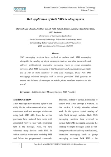
International Journal of Trend in ScientificResearch and Development (IJTSRD)International Open Access JournalISSN No: 2456 - 6470 www.ijtsrd.com Volume - 2 Issue – 5SMS Alarm System for Weather Station using Arduino and GSMMa May Zin OoOo, Dr. Nay Win Zaw, Daw Khin San WinDepartment of Electronic EngineeringEngineering,West Yangon Technological UniversityUniversity, Yangon, MyanmarABSTRACTNowadays, the monitoring of weather is utilized tomake many important decisions on a daily routine. So,by using one of the technologies, this alarm system isdesigned for real-time weather station using Arduinoand GSM module. This real-timetime weather station is tosend the LCD display and the alert to the user viashort message sending (SMS) in the wake of acritically of an event which is predefined by the user.One of the important applications of the system is tosend the alarm message to the defined mobile phonenumber. This system is to be convenient formonitoring the weather conditions without manualefforts.Keywords: Arduino Uno, GSM Module, Temperatureand Humidity Sensor (DHT11),HT11), Wind Speed Sensor,LCD display.INTRODUCTIONBasically, SMS alarm system is the warning whichsends important information of weather data. Weatheris the state of the atmosphere, that it is hot or cold,wet or dry, calm or stormy, clear or cloudy. Theweather conditions are closely relative to theproduction, the agricultural field, human life and soon. So people are trying to forecast the weathercondition with many methods. This system isdesigned for sending the important SMS that limitswind speedeed and temperature value by the user.PROPOSED SYSTEMArduino Uno (ATmega 328P)In SMS alarm system, Arduino Uno board is used.Arduino is an open source device, a prototyping boardconsisting of ATmega 328P microcontroller providinga 5V and 3.3V output voltage option. It takes inputvoltage from either connecting USB to the compcomputeror either using a coaxial cable using a portable powersupply. On the Arduino Microcontroller, sketches canbe uploaded using Arduino IDE (IntegratedDevelopment Environment).It has 14 digitalinput/output pins (of which 6 can be used as PWMoutputs),), 6 analog inputs, a 16 MHz crystal oscillator,a USB connection, a power jack, an ICSP header, anda reset button. It contains everything needed tosupport the microcontroller; simply connect it to acomputer with a USB cable or power it with a AC-toACDC adapter or battery to get started. It takes inputvoltage in between 7-12V.Features: Microcontroller: ATmega328 Operating Voltage: 5V Input Voltage (recommended): 7-12V7 Input Voltage (limits): 6-20V20V Digital I/O Pins:14 (of which 6 provide PWMoutput) Analog Input Pins: 6 DC Current per I/O Pin: 40 mA DC Current for 3.3V Pin: 50 mA Flash Memory: 32 KB of which 0.5 KB used byboot loader SRAM: 2 KB EEPROM: 1 KB Clock Speed: 16 MHz SRAM: 2 KB EEPROM: 1 KB Clock Speed: 16 MHzSoftware Requirements:The Arduino is open source Integrated DevelopmentEnvironment or Arduino Software (IDE). It contains atext editor for writing code, a message area, a text@ IJTSRD Available Online @ wwwwww. ijtsrd. com Volume – 2 Issue – 5 Jul-AugAug 2018Page: 1903
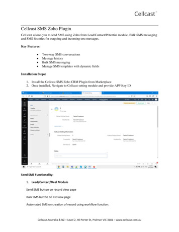
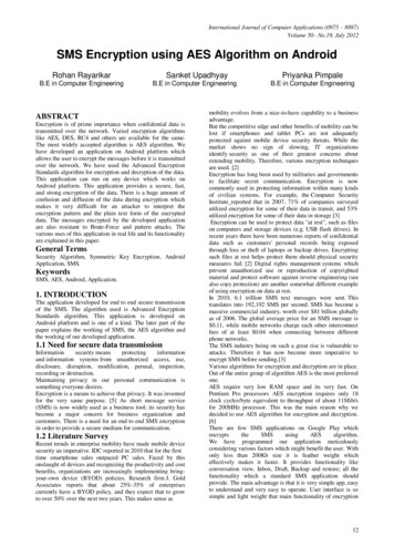
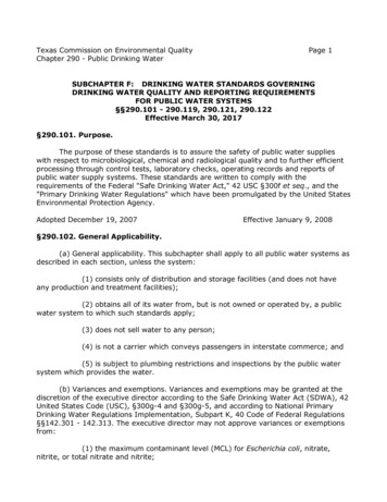
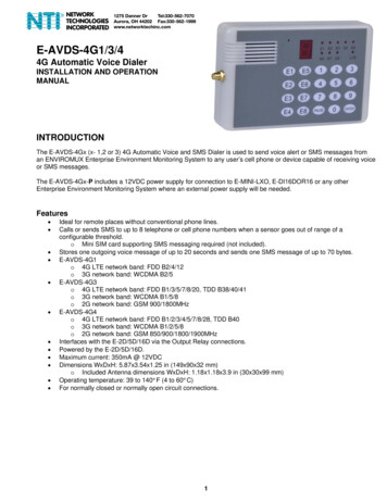
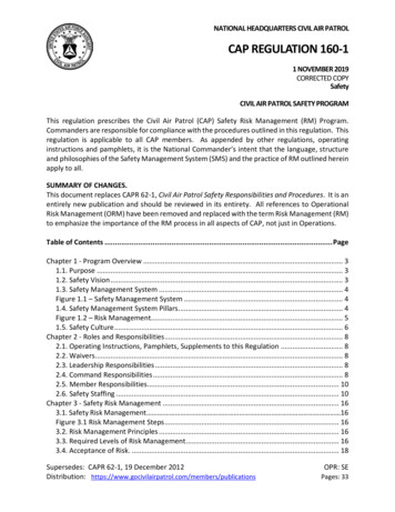
International Journal of Trend in Scientific Research and Development (IJTSRD) ISSN: 2456-6470console, a toolbar with buttons for common functionsand a series of menus.Figure1. Arduino Uno (ATmega 328P)GSM Module (SIM 900A)GSM/GPRS Modem-RS232 is built with Dual BandGSM/GPRS engine-SIM900A, works on frequencies900/1800 MHz. The Modem is coming with RS232interface, which allows for connecting PC as well asmicrocontroller with RS232 Chip (MAX232). Thebaud rate is configurable from 9600-115200 throughAT command. The GSM/GPRS Modem is havinginternal TCP/IP stack to connect with internet viaGPRS. It is suitable for SMS, Voice as well as DATAtransfer application in M2M interface. The onboardregulated power supply allows the wide rangeunregulated power supply. Using this modem, audiocalls, SMS, Read SMS (attend the incoming calls andinternet etc.) is made through simple AT commands.Features: Dual band GSM/GPRS 900/1800MHz. Configurable baud rate. SIM card holder. Built in network status LED. Inbuilt powerful TCP/IP protocol stacks forinternet data transfer over GPRS. Control via AT commands. Low power consumption: 1.5mA (sleep mode).Figure2. GSM module (SIM 900A)DHT11 SensorThe DHT11 is a temperature and humidity sensor. Itis calibrated against a digital signal output. TheDHT11 ensures reliability, high efficiency andstability for a long time which is present with the helpof this digital-signal-acquisition exclusive technique.This temperature and humidity sensor have an NTCtemperature component for measuring the temperatureand a very high-performance 8-bit microcontrollerconnected for humidity, which is cost effective andprovides an excellent quality and fast response abilitywith anti-interference. It consists of 4 pins from left toright Vcc, Data, NC (not connected) and GND. Thereare mainly three (Vcc, Data and GND) pins which areused.Features: Full range temperature compensated. Relative measuring of humidity and temperature. Calibrated digital signal. Outstanding long-term stability. Extra components not needed. Long transmission distance. Low power consumption. 4 pins packaged and fully interchangeable.Figure3. DHT11Wind Speed SensorWind speed, or wind velocity, is a fundamentalatmospheric rate. Wind speed is the rate of themovement of wind in distance per unit of time. Inother word it is the rate of movement of air flow.When the air is moving from high pressure to lowpressure then the wind speed is occur. It can bereported in a couple of ways: knots or nautical milesper hour, or statute miles per hour. Besides being usedas part of a weather monitoring station there are manyother situations where measurement and knowledge ofthe wind condition helps in decision-making such aspollution control, safety of tall structures, control ofwind turbines, studies on the effects of wind on crops,management of ships and aircraft landing systems.@ IJTSRD Available Online @ www. ijtsrd. com Volume – 2 Issue – 5 Jul-Aug 2018Page: 1904
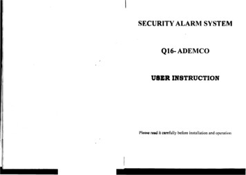
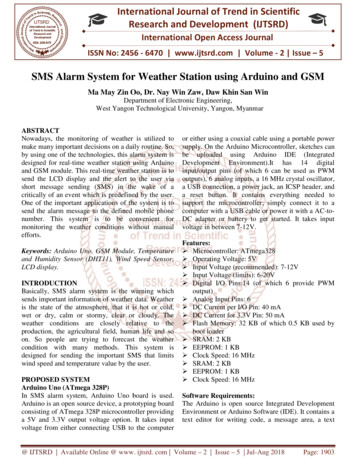
International Journal of Trend in Scientific Research and Development (IJTSRD) ISSN: 2456-6470Moreover, by using anemometer we able to measurewind speed which is useful to predict when the stormswill reach a certain area, what equipment might benecessary for the outdoors and how much preparationan individual might need to take to be safe withintheir home during inclement weather. Generally, windspeed is measured with an anemometer.Figure4. Wind speed sensorFeatures: DC power supply: 10 30V DC. Communication Interface: Pulse output. Measuring range: 0 60m/s. Dynamic response time: 0.5s. Starting wind speed: 0.2m/s. Load capacity: NPN 100mA.Liquid Crystal Display (LCD)A liquid crystal display (LCD) is a display modulewith liquid crystals and backlight by LEDs. A 16x2LCD display consists of two rows of display witheach row consisting of 16 characters. LCD Modulehas 16 pins and operates with 5V. Power pins i.e. pins1, 2, 3, 15 and 16 are used to supply for the module aswell as the backlight LEDs. The voltage to thecontract adjust pin (Pin 3 or VEE) is usually givenfrom a potentiometer and will control the contrast ofthe actual display when the POT is adjusted. There are8 data pins for transmitting 8bits of data i.e., 1 byte ofdata at a time. The LCD can be used in either 8bitmode or 4bit mode.Figure5. LCD displayI²C CommunicationI²C is a multi-master protocol that uses 2 signal lines.The two I²C signals are called ‘serial data’ (SDA) and‘serial clock’ (SCL). There is no need of chip select(slave select) or arbitration logic. Virtually anynumber of slaves and any number of masters can beconnected onto these 2 signal lines and communicatebetween each other using a protocol that defines: 7-bits slave addresses: each device connected tothe bus has got such a unique address data divided into 8-bit bytes a few control bits for controlling thecommunication start, end, direction and for anacknowledgment mechanism.Physically, the I²C bus consists of the 2 active wiresSDA and SCL and a ground connection. The activewires are both bi-directional. The I2C protocolspecification states that the IC that initiates a datatransfer on the bus is considered the Bus Master.Consequently, at that time, all the other ICs areregarded to be Bus Slaves.Figure6. 16x2 LCD I2C modulesDESIGN AND IMPLEMENTATIONIn this system, Arduino and GSM module are usedwhich connected to the input sensors “wind speed andtemperature” and to output SMS alarm message andLCD display. Arduino is an open source hardwareprototyping platform, which allows an easyimplementation of sensors and interactive element.Firstly, all the components are initialized by supplyingthe required power of 5V. The wind speed sensor isconnected to digital pin 4 of Arduino Uno board.DHT11 is a sensor to get the temperature andhumidity value which is also connected to digital pin5 of Arduino Uno board.Figure7. Block diagram of SMS alarm system forweather station@ IJTSRD Available Online @ www. ijtsrd. com Volume – 2 Issue – 5 Jul-Aug 2018Page: 1905
International Journal of Trend in Scientific Research and Development (IJTSRD) ISSN: 2456-6470The Arduino reads the input sensors by mean ofrelated pins and implements the program by IDEsoftware. It sends the alarm message to the definedmobile phone number by using GSM module whenmaximum temperature and wind speed are reached.The gathered data is serially fed into a computer,which uses the com port to communicate with theArduino device and the data recorded is stored in atext file. The GSM module is used to send/receivemessages and make/receive calls just like a mobilephone by using a SIM card by a network provider.The GSM shield is connected with Arduino board andthen plugging in a SIM card from an operator thatoffer GPRS coverage. The connection of the shieldmakes its TX to the digital pin 2 and RX to digital pin3 of the Arduino Uno board.When the temperature condition is over 40ºC, itsends the text “Warning! Temp SMS” to LCDdisplay. And also when wind speed condition isreached over 40 mph, it sends the text “Warning!Wind SMS” to LCD display.Figure10. LCD display result output overconditionFigure8. Schematic working diagram of the systemThe system is programmed to display data on LCDdisplay continuously. It is the real time result data ofthe system. So the important information of the windspeed and temperature data is clearly seen on the LCDdisplay.Once the temperature goes above 40 C, a SMS alertmessage is sent “Warning!!!, Temperature is over 40Degree Celsius.” to the defined mobile phone numberby using GSM module.Figure11. SMS alarm message for overtemperatureFigure9. LCD display result outputAnd also, the wind speed data goes above 40 mph, aSMS alert message is sent “Warning!!!, Wind Speedis over 40 MPH.” to the defined mobile phonenumber.@ IJTSRD Available Online @ www. ijtsrd. com Volume – 2 Issue – 5 Jul-Aug 2018Page: 1906
International Journal of Trend in Scientific Research and Development (IJTSRD) ISSN: 2456-6470REFERENCES1. Brian W. Evans. Arduino ProgrammingNotebook. San Francisco, California, USA. FirstEdition August 2007.2. Ph.D Jack Purdum. Beginning C for Arduino. 233Spring Street, 6th Floor, New York. Copyright@2012.3. Karthik Krishnamurthi, Suraj Thapa, LokeshKothari, Arun Prakash. “Arduino Based WeatherMonitoring System”, International Journal ofEngineering Research and General ScienceVolume 3, Issue 2, March-April, 2015.Figure12. SMS alarm message for over wind speedCONCLUSIONThe system deals with designing a simple and lowcost real-time weather station using Arduino Uno,GSM module, temperature and humidity sensor(DHT11), wind speed sensor to monitor weatherconditions of the desired location and send it to adefined mobile phone number at distant locationthrough SMS. Effective integration technology hasbeen used to ensure the sustainability of the station.Versatility in execution of data takes the pride of theeffectiveness of the product in different conditions.This concludes that the present work was a successand it will provide a competent method for monitoringreal time weather readings and help farmers whoselivelihood depends on the weather in a country toproduce better quality crops. The SMS alarm messagesystem is often utilized to make many importantdecisions on a daily routine. These weather forecastsare issued to reduce property damage, reduce cropdamage, save lives, and so on. Therefore, Limitationsof the system are mentioned below: The amount of sensor is less. It is not web based system. It is needed the GSM/GPRS network for SMSmessaging.4. P. Ramchandar Rao, S. Sanjay Kumar, Ch.Rajendra Prasad. “Garbage Monitoring Systemusing Arduino”, International Journal of Trend inScientific Research and Development (IJTSRD),Volume 1, Issue 6,Sep – Oct, 2017.5. Prof. P. R. Jawale, Mr. V. S. Ghayal, Mr. D. M.Shende, Ms. S. N. Ghogale, Ms. V. B. Nagare.“Prepaid Energy Meter using Arduino and GSMModule”, International Journal of Research inAdvent Technology (IJRAT), E-ISSN: 2321-9637,April 2017.6. https://arduino.cc7. https://robocraft.ru8. https://github.comFUTURE SCOPEIn future, sensors are used as much to analyze theweather station and a web interface or service to feedthe data directly to internet could also be built. Thesystem can be improved by adding new functionalitieslike wind direction sensor, LDR sensor, rain fallsensor, moisture sensor and etc. Furthermore, thissystem can be used in the production, the agriculturalfield and etc.@ IJTSRD Available Online @ www. ijtsrd. com Volume – 2 Issue – 5 Jul-Aug 2018Page: 1907
SMS Alarm System for Weather Station using Arduino and GSM Ma May Zin Oo Department of Electronic Engineering West Yangon Technological University ABSTRACT Nowadays, the monitoring of weather is utilized to make many important decisions on a daily routine. So, by using one of the technologies, this alarm system is designed for real-time weather station using Arduino and GSM module. This real .