Transcription
Automated Contact ResistanceTesterCR-2604
What’s New2
What’s New Summary of Software Improvements:– Improved CRESHost V1.3.9 Print/Save image support for Win7 Added view of diagnostic log file Support Win7 USB connection at power up Improved verification file format for easier PASS/FAIL display– Improvements made for better reliable USB connectivity withCRESHost V1.3.9– Software adjustment to incorporate the revision change onmicroprocessor within CR tester.3
CR-260X Users4
CR-2604 Payback PeriodsCustomer Example Production Use– Customer utilizes CR-2604 toavoid throwing out good pins– Customer uses 385,693 pins per Lab Use– Customer utilizes CR-2604 on aproject basis– Cost savings derived from savingsquarter at average cost of 1.89of Tester & Engineering time each 3000 per project– Customer saves average of 10%Pins that were previously thrown– 9 project Payback Period( 1.5 years)away– 1 month Payback period5
CR-2604Contact Resistance Tester Incoming Socket Inspection Routine Socket Performance Verification Pin Resistance/Opens Pin Shorting Socket Preventative Maintenance6
IntroductionTest Socket What is a test socket?The single interface between adevice being tested and a 100K ATE How do you know the testsocket is “good”? How do you test a testsocket?7
Introduction – Industry Conditions Decreasing Pitches– 1.27mm 1mm0.8mm0.5mm 0.4mm – Smaller pitches require newand more complex socketprobe designs. RoHS Directive– The proliferation of solder ballcompositions such as SAC105,SAC305 and SAC405 lead tonew contamination problems. Increasing Device I/O Count &Power– Systems on chip are driving upI/O counts.– High performance devices arerequiring more power.8
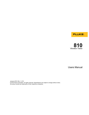
Introduction – Industry NeedProblem: Inconsistent and unreliable socketperformanceCause: Contamination build-up on socket pinsWhy is high contact resistance bad?– Can cause excessive pin heating– Limits available power on supply pinsSocket Pin With New PinsWhy is inconsistent contact resistance bad?– Decreased yield– Intermittent failures– Equipment downtime to resolve “problem”– Difficult to detect and isolate in ATEA system is needed to identify failing socket pinsbefore they impact production schedules andyield.– High contact resistance is an early indicator offailing socket pins caused by wear or contamination– Sometimes ATE capital equipment can measurethis, but the time is expensive and not flexible– Both the contact (spring-loaded pin, elastomer,etc) and the device interface need to be measuredSolution: A device to independently verify asocket’s performance by measuring theresistance of each pin.When?How many cycles?Which pins?Socket Pin With Contaminated Tips9
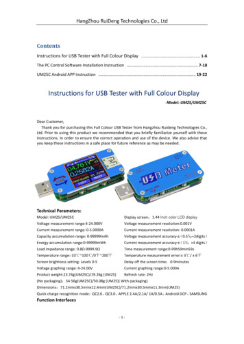
CR-2604 Socket ContactResistance Tester The CR-2604 tester is a portable, easy to use toolused to validate socket integrity by measuringcontact resistance. Measure your socket's contact resistance usingthis PC compatible, lightweight, measuring tool. The CR-2604 tester will allow you to identify thelocations of open or high resistance pins withinyour socket array. The user interface is displayed on a Windows XPor Windows 7 computer via USB connection. No standard maintenance required on tester. Theunit has 8 internal low-drift precision 4-Wireresistors for reference. Before each measurementcycle, these resistors are measured to calibratethe measurement circuitry.10
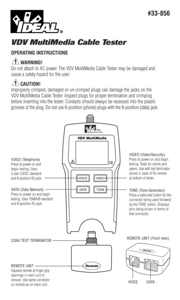
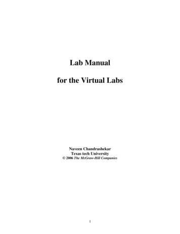
Solution Overview Shorting Device: Shorting/Daisy chain packageSocket and Lid: Spring Probe Socket to be testedInterface Board: Footprint specific, socket interface card.Socket Tester Base: Electronic circuitry to perform tester functionHost Computer: Runs Tester software to configure tester and reportresults11
Resistance MeasurementMethodologyWORST PIN MEASUREMENT METHOD 2-Wire Standard Approach– NOT used by the CR-2604 Tester– Measure the DUT resistance plus the test lead resistance– Cannot accurately measure low-valued resistors (pins)– Typically can only measure Pin pairs plus lead resistance losses (NOT individualPins)ReferencePoint #1ReferencePoint #2ReferencePoint #1ReferencePoint #212
Resistance MeasurementMethodologyBEST PIN MEASUREMENT METHOD 4-Wire (Kelvin) Approach– USED by the CR-2604 Tester– Eliminates PCB and Cabling From Measurement– Requires Separate Current & Voltage Path– Accurately measures low-valued resistors– Allows for single pin measurement13
CR-2604 MeasuresOnly the Pin Resistance (no bulk)? 4 wire measurements Tester interconnects, traces, and switches not included in measurement 4-Wire reference at DUT pad14
Electrical System Block DiagramUsing Shorting Block15
Electrical System Block DiagramUsing Daisy Chain Device16
Socket Mountingon Interface Board17
Interface Boards The CR-2604 uses interface boards to map a socket footprint to thecommon tester footprint ALL BOARDS PURCHASED FOR USE ON THE CR2600 or CR2601 ARECOMPATIBLE WITH THE CR2604 Up to 2604 test points (5208 4-Wire traces) Interface Board is 7”x7”, variable thickness (usually 0.093” – 0.125”thick)Interface Board Top ViewInterface Board Bottom View18
CRES Host Software – UserInterface Controls CR-2604 tester and allows measured values on all pins tobe viewed Allows manual saving of socket data for later analysis (CSVFormat) Compares multiple data sets for trend analysis Configurable color-coded resistance thresholds Requires Windows XP or Windows 7 computer with Available USBPort19
CRES Host Software – UserInterface Socket Labeling, notes about the test conditions Administrator and User modes. Password Protected20
Test Probe Pen The included handheld test probe allows easy identification of failed pins After performing a measurement, probe mode shows the specified pin onthe computer screen when it is touched with the test probe pen21
CR-2604Contact Resistance Tester Specifications 4-wire pin measurements up to bulk of shorting plate. Resistance measurement range: 0 ohms to 300 ohms 0.5% or 5 mΩ Overall Accuracy, whichever is greater (usingWells-CTI Verification Board, see slide 24) Maximum socket I/O supported 2604 pins Force Current 25mA (variable, not adjustable) Average Measurement Time : 25 Pins / Second (depending onaveraging setting)22
Options –Universal Manual Actuator Allows socket to be testedwithout attaching tointerface board withscrews. Enables quick socketchanges The plunge depth ofactuator pressure pad isconfigurable andrepeatable. Comes with replaceablepressure pads supportingpackages from 10mm to50mm.Manual Actuator Video23
Options –Universal Interface Boards Requires Universal Manual Actuator Unit.Inexpensive quick turn generic interface boards compared to custom designs.Quick socket change out when testing multiple sockets.Stocked and post-drilled to accommodate socket alignment featuresCan often support multiple socket footprintsAvailable for pitches:Part NumberPitchMatrix SizePad SizeMax Dowel Pin LengthEM-0099-1001.27mm51x5130 mil2.54mmEM-0099-1011.0mm51x5125 mil2.54mmEM-0099-1020.8mm40x4017 mil2.54mmEM-0099-1030.65mm40x4014.9 mil2.54mmEM-0099-1040.5mm40x4012 mil2.54mm24
Options –PCB/BGA Shorting Packages BGA shorting packages 0.8mm and above pitchesavailable Built to customer providedpackage specificationAdvantages Ball interfacevery similar tocustomerpackage Cost perdevice isrelatively low Solder es Solder ballswill wear out(estimated 50100 insertions) Reducedmeasurementrepeatability Minimum lot of25 pieces25Please provide package details for quotation
OptionsLGA/QFN Shorting Packages PCB and Machined available Various plating options Built to customer provided packagespecification WELLS-CTI recommends Gold plated padsfor best repeatability26Please provide package details for quotation
Measurement System Repeatability To validate performance we have created verification cards(EM-0125) which are fabricated using commerciallyavailable precision resistors– The resistors are soldered to the verification card toeliminate any variance due to mechanically cycling theresistors. During the verification test each of the channels is used tomeasure the same resistor providing 2604 data points For repeatability verification the board is removed and reinstalled and the test repeated. This repeat is performed 5times producing 5 sets of data. Each data set includes10,416 measurements The validation is conducted with 11 different resistancesusing different precision resistor boards. The resistorvalues range from 2.5 mΩ to 60,000 mΩ, or 60 ohms27
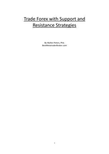
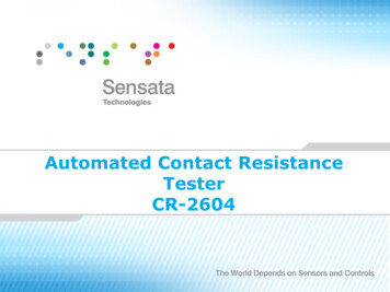
Measurement System RepeatabilityR (mΩ) σ (uΩ)6σ 01074.416446.47The results are shown graphically. Note that the resistance values arereported in mili-ohms (mΩ) however the units of the std.dev σ are microohms (μΩ)The data shows that:–the standard deviation is always less than 1% and, at the resistance of a typicalpin, 50 mΩ the std. dev is .05%.– For 6 σ, which will include 99.9997% of the population, the error is lessthan 0.5% at the resistances of interest.28
The CR-2604 tester is a portable, easy to use tool used to validate socket integrity by measuring contact resistance. Measure your socket's contact resistance using this PC compatible, lightweight, measuring tool. The CR-2604 tester will allow you to identify the locations of open or high resistance pins within your socket array.