Transcription
Fatigue Life Analysis of Holed Component in Aircraft StucturesByMuhammad Zulfaqqar bin Mohd Kasim14367Dissertation submitted in fulfilment ofthe requirement for theBachelor of Engineering (Hons.)(Mechanical)May 2015Universiti Teknologi PETRONASBandar Seri Iskandar32610 Tronoh,Perak Darul Ridzuan
TABLE OF CONTENTContentPagesAbstractiiiChapter 1: Introduction11.1Background of Study11.2Problem Statement21.3Objective of Study31.4Scope of Study1.4.1Determination of component/structure to be analysed31.4.2Finite Element (FE) analysis and analytical method6Fatigue life estimation1.4.3Seeking improvement for current Fatigue life6estimation methodChapter 2: Literature Review72.1Fatigue life prediction through local stress-strain concept72.2Von Mises Criterion72.3Cyclic stress-strain relation and plastic revision under8multi-axial loading2.4Stress Analysis92.4.1Stress Analysis based on Finite Element Method102.4.2Neuber’s rule122.5Fatigue Life Analysis132.6Fatigue Cumulative Damage14i
Chapter 3: Methodology3.116Analysis Tool163.1.1ANSYS Workbence 15.0.7 Software163.1.2CATIA V5 Software173.2Project Activity173.3Analysis Work203.4Project Flowchart213.4Gantt Chart (FYP 1) and Project Milestones223.5Gantt Chart (FYP 2) and Project Milestones23Chapter 4: Results and discussion254.1Stress Analysis254.2Fatigue Life Analysis294.2.1Stress Concentration-fatigue life relationship304.2.2Fatigue life estimation of model under typical33flight loading condition4.3Application of the developed method to the example of the36actual aircraft structure. (Wing rib #7, Zenair CH601XLlight aircraft)Chapter 5: Conclusion and Recommendation42References43Appendices45ii
ABSTRACTAircraft structure with holes was thought to have a significant impact towards fatiguelife. Holes had been stress concentrators where high magnitude of stress will be focused aroundit and potentially be the fatigue crack imitation site. Stress and fatigue analysis were donethrough finite element simulation to see the effect of stress concentration upon the fatigue lifeof a plate-with-hole model. This model has been a simple representation of the complex holedaircraft structures. It was found out that the result obtained was consistent to the assumptionsmade where parts with stress concentration will have a shorter fatigue life due to the severityof damage it face as cyclic loading is being applied to it. The current practice of fatigue lifeprediction is usually through the process of full scale fatigue simulation which is a costintensive and a very time consuming process and through lab experiment which considerablycomplicated and time consuming as well. This study had been focusing on creating a fatiguelife estimation that is simple and reliable. In this study, a method that highly focuses on theusage of finite element software has been used and it was found out that the result isconvincingly simple and reliable with only 0.5% error.iii
1.INTRODUCTION1.1Background of studyMetal fatigue is the most common type failure mechanism which occurs in aircraftstructures. According to data gathered by the materialstoday journal, published in November2002, metal fatigue had occupied 55% of the percentage of failure modes in an aircraft,signifying that, metal fatigue is a serious issue within aviation industry. There are severalfactors which could lead to metal fatigue in design, such as the size factor, the surfaceroughness, metallurgical defects within grains, and stress concentrations. However, for thisstudy, focus will be thoroughly given to the stress concentration factors and to be morespecific, stress concentrators in the form of holes.Through non-destructive tests which were done in the entire aircraft section, fatiguesign in the form of small cracks were mostly found in the area of holed parts. These holedparts could be the rivet holes, bolt holes, panel opening cut outs, window frames, and doorframes. Wherever there are openings or discontinuity on the fuselage, wings, frames or othermajor aircraft structures, there will always be stress concentrations. A simulation was done tosee how the stress concentrator in the form of hole affects the fatigue life of the structure andthe it was further discussed in result in discussion section.In addition to that, a huge emphasize was also given to the development of the simplerand reliable fatigue life prediction of aircraft structures. Current method of fatigue lifeprediction which was used by the aviation industry is currently very costly and timeconsuming (further discussed in problem statement part) and this study was done to develop asimpler method of estimation which will hopefully be useful in industry in cutting costs andtime consumptions as well as to provide a simpler method of analysis for future researches.As established in S.J. Findlay and N.D. Harrison in their article, Why aircraft failpublished in November 2002 edition of materialstoday journal, the fatigue failure processinvolves three phases. First, the crack initiation phase which occur first and followed by thecrack propagation phase, at which the crack spreads. When the crack reaches the critical size,the final unstable rapid crack propagation occurs, which will leads to the third and final phasewhich is the failure phase. This study was only focusing onto the crack initiation phase,which is the phase where the microcracks just start to appear after several cycles of loadinginput. This particular phase is very important for analysis because it reflects of the real1
durability of the structure itself. Second and third phases of the fatigue life are no longerrelevant for this analysis because the rate of damage will only accelerate up until the structurefailure since the crack was already formed (in the first phase: crack initiation). For the fatiguelife prediction of the holed aircraft structure, strain-life method via Finite Element analysisand analytical analysis approach will be utilised as the main analysis tool. Details for theplanned analysis and simulation methods were further discussed in the followingmethodology section.1.2Problem statementThe estimation of fatigue life of an aircraft could be done through full scale fatiguetesting by introducing loading histories that are approximately similar like the real operationcondition. This method had proven to be reliable in providing quite a good fatigue lifeestimates and was widely used by aircraft manufacturers. However, despite its reliability, thismethod is very time consuming. A full-scale fatigue test could take months to complete andto get results. Additionally, the full-scale fatigue test could be very costly as it requires thewhole aircraft to be tested. Having this fact, the full scale fatigue test was absolutely notviable for research purposes and this demands an alternative which is fairly simple andreliable enough to be used as a research tool for the metal fatigue, especially in aircraftstructures.As mentioned earlier in the background of study section, it is very common to find thefatigue signs at the holed part of the aircraft structures. This holed part includes, the rivetholes, bolt holes, lugs, fuselage cut outs (window and door frames) and etc. These holes wereknown to be stress concentrators in aircraft structures, in which the stress in this area ismultiple times higher than area without any cut outs or open holes. Upon cycles of stresses,these holed areas are the most susceptible place to experience metal fatigue, especially at thestructural parts which have to bear high magnitude of loading frequently. So, it is crucial toinvestigate further about how the presence of stress concentrators affects the fatigue life ofaircraft structures.2
1.3Objective of studyThrough the issues stated earlier in the problem statement section, several objectiveswere devised for this study which will cover all the stated issues. The objectives are; To provide a fairly simple and reliable method to estimate the aircraft structure’sfatigue life. To determine how does the presence of stress concentrators (holes) could affect thefatigue life of aircraft structures.1.4Scope of studyAs stated in the objective part, this study is mainly to develop a simple and reliablefatigue life prediction of aircraft structures from the existing knowledge of fatigue predictionsdeveloped by the early researches and also to determine how does the presence of hole inaircraft structures affects the fatigue life of it. There are several studies done previouslyregarding this topic and this study had been using them as references and guide in ensuringthe result produced through the analysis is proper and accurate.1.4.1Determination of type of structure and materials to be analysedFocus and attention will be given to the holed aircraft structures/component partswhich some of them are very critical in aircraft operation. The reason for this particular typeof structure was chosen is due to the presence of hole which may act as stress concentrator inthe structure and is highly susceptible to fatigue damage. To study this, a simple virtualmodel of plate with a hole will be made to represent the holed aircraft structure or componentparts such as the structural frame (stringers), aircraft skin, bulkheads, lugs and attachmentpoints and it will be tested through finite element (FE) method to see the stress reaction uponthis type of structure and the effect of this stress concentrator to the overall life of thestructure under the simulated working condition.SAE 1045 (medium carbon steel) had been chosen as the material of choice to betested in this analysis. The main reason for this material had been chosen is mainly to get a3
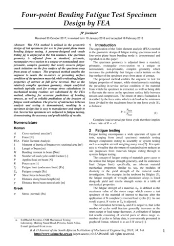
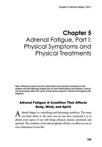
material match for result validation process and this validation process will be done bycomparing the result gained from this study to previous research work’s results. In this study,the SAE 1045 steel is being virtually tested under the tensile stress through finite element(FE) analysis which mimics the stress condition of the pressurized fuselage in an aircraft. Inaddition to that, the similar method which was utilised for the simple plate-with-hole modelwas also used to one of the real-life component in aircraft structure, made up of 7075-T6Aluminium alloy (commonly used material in aircraft) that has holes associated to thestructure to estimate its fatigue life as a real-life case example.Depicted in the following pages are the examples of holed structures/parts that are exists inaircrafts;Figure 1: Frame of Boeing 737-400 aircraft retrieved from Boeing 737-400 Structure RepairManual (SRM), Chapter 53: Fuselage, Subject 53-00-07 p.2024
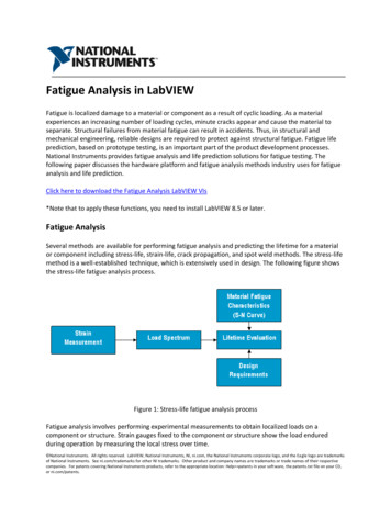
Figure 2: Side view of the frame of Boeing 737-400 aircraft retrieved (frame with fastenerholes) from Boeing 737-400 Structure Repair Manual (SRM), Chapter 53: Fuselage, Subject53-00-07 p.203Figure 3: Holed frame part of Boeing 737-400 aircraft retrieved from Boeing 737-400Structure Repair Manual (SRM), Chapter 53: Fuselage, Subject 53-80-07 (fuselage frames)p.2045
1.4.2Finite Element (FE) analysis and analytical method in stressanalysis and fatigue life estimationBoth analytical calculations and Finite Element (FE) analysis were associated alongwith this method. In this research work, a method of fatigue life analysis that emphasizes onheavy usage of Finite Element (FE) and analytical analysis instead of full-scale/small-scaletest was done in order to solve the high cost and time consumption to get the estimation offatigue life result. Finite Element (FE) method which was adopted through the usage ofANSYS workbench 15.0.7 software is important for the stress analysis of the model wherethe effect of localized stress (stress concentration) in holed location of model was observed.Additionally, FE was also used to find the maximum local stress that is vital for the fatiguelife calculation. Meanwhile, simple analytical calculations were utilized to calculate thefatigue cycles, fatigue cumulative damage, and several other parameters by applying therelated governing equations, rules, and theories.1.4.3Seeking improvement for current fatigue life estimation methodDuring the course of this study too, a lot of research were done through several otherrelated research works, text books, journals and articles that are related to this topic to helpfurther increase the understanding of the topic and might as well find a way to furtherimprove the established method produced by the earlier study such as Maksimovic’s and etc.in order to achieve a more relevant and accurate results. Any input which might be useful inproviding more accurate results and might be useful in the simplification process of thefatigue life estimation method obtained through these sources will be taken into considerationin the research and will be adjusted accordingly to suit the designed method.6
2.LITERATURE REVIEW2.1Fatigue life prediction through local stress-strain conceptThe local stress-strain concept was used as a tool to establish a simpler and a morereliable way to create a fatigue life prediction for aircraft structures. The basis for the localstress-strain approach is the local fatigue response of the material at the critical point (site ofcrack initiation) is comparable to the fatigue response of a small, simpler-shaped smoothspecimen subjected to the same cyclic of strains and stresses. What the premise above meant,it is possible to determine the cyclic stress-strain response of the critical material through thesimpler-shaped smooth specimen, by replicating the same load history applied on the criticalmaterial. It is to be noted that the phenomena of cyclic hardening, cyclic softening, and thesequential loading accumulates the fatigue damage was presumed to be at the same point thecritical point (crack initiation site) in the structural component which to be simulated. Theelastic-plastic behaviour will need to be addressed properly as well during while utilising thisconcept. (Maksimovic, 2005).2.2Von Mises CriterionVon Mises criterion will be the basis in order to obtain the equivalent strain. Theequation below is the basic equation from the Von Mises hypothesis which was also knownas the Octahedral Shear strain theory (Fatemi, 2010) and it will be derived according to theASME Boiler and Pressure Vessel code Procedure (1988) to find the equivalent stress range.This basis equation was composed using the Von Mises criterion, axial strains and shearstrains;In the formula above (1)are mean of the three main strains and ν is thePoisson’s ratio. Meanwhile, the derived equation is as follows;7
Next, by utilising the static yield theory of multi-axial loading and Von Mises criterion, theequation derived to get the equivalent multi-axial stress range is:As for the formula (3),theare the main three stresses of single axial.andobtained by the above equations will be used later in the Cycle stress-strain formulato find develop the Cyclic stress-strain curve.2.3Cyclic stress-strain relation and Plastic revision under Multi-axialloading.An elastic-plastic material, which was subjected to cyclic loading will have the strainstress history which will initially go through a transient state which asymptotes to a cyclicstate. (Maksimovic, 2005). Additionally, the behaviour of body, within this cyclic state canbe divided into three main region; Elastic region (recoverable deformation), Elastic-plasticregion (permanent deformation) and lastly, Failure.This cyclic-stress strain curve is particularly possible to be obtained by connecting thestable hysteresis loop’s tips for different strain amplitude in a fully reversed strain-controlledtest. However, tests for this purpose will not be conducted in this study due to the limitationof time and costs. The cyclic stress-strain curve will be obtained through calculation; utilisingthe Cyclic stress-strain formula (eq.4).The basis of the cyclic stress-strain formula comes from the Ramber-Osgoodequation. This equation (Ramber-Osgood equation) is basically the representation of multiaxial loading, stable cycle stress and strain curve in analytical form.Bothrepresent the equivalent range of local stress and strain in multi-axialloading; E is the Young’s Modulus/Modulus of Elasticity, n’ is the cyclic hardeningexponent; K’ is the cyclic strength coefficient,8andare equivalent elastic and
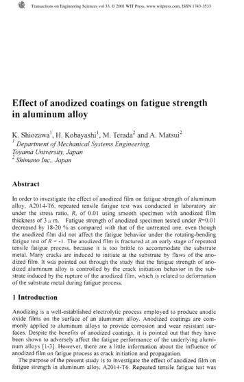
plastic stress range respectively. Maksimovic had utilized equation (4) along with the knownmaterial properties to define the cyclic stress-strain curve (figure 4) of the material tested.The curve also reflects the material behaviour towards cyclic loading.Figure 4: Cyclic stress-strain curve of SAE 1045 steel used in Maksimovic’s Fatigue LifeAnalysis of Aircraft Structural Component research2.4Stress AnalysisMaksimovic (2005) had also mentioned in his paper: Fatigue Life Analysis of AircraftStructural Components, stress analysis has two roles regarding to the fatigue life assessments.Firstly, to determine the area of component that is most susceptible to metal fatigue.Secondly, stress analysis is also important in providing means to overcome the localizednature of fatigue; that is to create alternative solution in preventing stress concentration and atthe same time, reducing the risk of metal fatigue.E. Vreudge of Metserve International (Metallurgical consultancy) had stated in hispublished Technical Brief literature (2001) that the stress concentration is one of the mostsignificant factors that are affecting metal fatigue. Thereby, the understanding of importanceof the stress concentration as one of the metal fatigue factor was already quite established.Not only that, it also had contributed a lot in the development of fatigue life prediction9
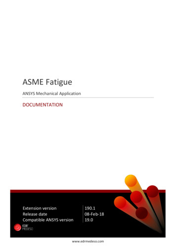
technique. Similar to what Maksimovic had done in his study, Teng & Chang (2003) havealso used a simple plate with central hole model for their Finite Element (FE) analysisIn their study, Stress distribution determination was done through the Finite Element(FE) Analysis because of its capability in evaluating stresses reliably for complex geometriesas well due its accuracy. Plasticity properties of the component at the stress concentrated areawill be considered as well.2.4.1Finite Element MethodAlongside the analytical method (calculation), Finite Element (FE) method wasutilised as well. FE Method was known for its accuracy in providing results throughsimulations. Other than known for its accuracy, Finite Element method has been a great toolto simulate operating conditions in terms of loading applications and predict how thoseloadings affects the structure; which will be the main focus in this study.Below is the result of stress analysis through Finite Element done by Maksimovic(2005) in his study. The plot is colour coded where the highest magnitude of stress wasrepresented by red and the lowest is represented by purple. From the Finite Element Analysisshown below, a pattern of stress distribution can be observed where the stress magnitude isthe highest at the side of the hole of the plate, which indicates the stress concentration points.Figure 5: FE analysis on plate-with-hole in S. Maksimovic’s paper; Fatigue LifeAnalysis of Aircraft Structural Component. (2005)10
Figure 6: Stress distribution graph by x-axis coordinate in S. Maksimovic’s paper;Fatigue Life Analysis of Aircraft Structural Component. (2005)Adopting a little bit different way, Teng & Chang (2003) had used a symmetricrepresentative model (a quarter of its holed plate) instead of using the whole plate-with-holemodel. This had allow a very refined meshing on the part, which help the analysis to behighly accurate without having a very long time to solve the analysis. Below is the modelrepresentation used by Teng & Chang (2003) in their study and also their result after runningthe Finite Element (FE) solver for the stress analysis.Figure 7: Model used by Teng & Chang (2003) for FE stress analysis11
In determining the stresses and strains, non-linear (elastic-plastic) analysis was used andwithin this non-linear analysis, the cyclic curve of material behaviour was also used. Theobtained value of local stresses was then used in fatigue life estimation.2.4.2Neuber’s RuleAs loading is being applied to a notched structural component, the highly stressed partis localized around the notch root area. To compute the local stresses and strains at thelocalized stress area, Neuber’s rule is used in conjunction with the cyclic stress-strainproperties as well as Fatigue stress concentration factor. The Neuber’s rule is as follows;Where kt is theoretical stress concentration factor,factor andthe local stress concentrationis the local strain concentration factor. Meanwhile, ε is local strain,σ is local stress, e is nominal strain and S is nominal stress. (Young, Budynas and Sadegh,2012)This relationship was then modified for the application of the fatigue loading (Topper, Wetzeland Morrow, 1969) by including the fatigue stress concentration factor along with thenominal stress rangeinnominal strain range, local stress range, local strain rangeto become:When the loads are too small that the material behaviour of the whole component isnominally elastic, thenand equation (6) becomes:Since the left-hand side of the above equation was known for a given loading and geometry,this alternate form of Neuber’s rule equation provides a relation in betweenandwhich are unknowns. Both of the local stress and strain ranges mentioned earlier are also12
related through the material stress-strain behaviour. These two relations; Neuber’s rule andmaterial stress-strain law determinesand.Next, substitution of cyclic stress relation equation (8) into the equation (6) will giveexpression that relates local stress range to the applied nominal stress range andthrough this,hencecould be solved.The value ofwill then substituted back in equation (8) to solve for. For the case ofmulti axial loading, equation (5) will need to be modified that all the stresses and strains needto be replaced with equivalent stresses and strains (look section 2.1).Below is the modified equation:-2.5Fatigue Life AnalysisMaksimovic (2005), in his paper had used strain based approach for the fatigue lifeestimation. In this approach, local stresses and strains at notches σ and ε were estimated andplayed a main role in determining fatigue life predictions. According to Rahman et. al.(2009), this kind of approach (strain-life approach) involved the techniques of converting theloading history, geometry and material properties (monotonic and cyclic) input to becomefatigue life estimation. The analytical method of this approach was based on the low-cyclefatigue data in terms of strain-life curve and it (strain-life curve) was preferred to be used topresent the strain cyclic resistance of materials by describing material’s endurance as functionfor both elastic and plastic strain amplitude. Below is the equation which relates the appliedstrain range and fatigue life under multi-axial loading and this equation was known asMorrow equation.13
In the previous equation, (equation 11)is the equivalent strain range; b is the Basqun’scoefficient; c is the fatigue ductility exponent;andis fatigue ductility coefficient and2.6is Basquin’s fatigue strength coefficient;is the local mean stress.Fatigue Cumulative DamageThe damage induced by metal fatigue is accumulative in nature. The damage mayhave been started during the early days of its usage and under the repetitive loadings that maybe well below the yield point. This process is particularly dangerous because a single loadapplication would not show any apparent ill-effect. (Roylance, 2001). So, to estimate thefatigue damage under a spectrum of variable amplitude of repetitive loading, Palmgren-Minerrule was used. Maksimovic (2005) had adopted this law in his paper as well to estimate thefatigue damage due to variable amplitude of cyclic loading which represents the load thataircraft structure/components have to bear during its life.Miner law equation is as follows;Where, D represents the damage due to fatigue, Nfi is the cycle count at the time of failureunder axial loading and ni is the actual cycle count at the adequate stress level. However, tosuit the strain-life approach of fatigue life estimation, the above equation (14) will beexpressed as follows;Where T is the block load spectrum during structure failure.14
The block load spectrum concept has been used in Maksimovic’s had considered bothconstant and variable amplitude of loading in order to increase the accuracy and realism(compared to constant amplitude loading application) and at the same time reduces thecomplication of the real time history (variable amplitude loading) the of the cyclic stressapplication upon the investigated aircraft structure during flight (Fatemi, 2009).Figure 8: Block load spectrum used in Maksimovic’s paper; Fatigue Life Analysis of AircraftStructural Component. (2005)Table 1: Block load cycles used in Maksimovic’s paper; Fatigue Life Analysis of AircraftStructural Component. (2005)The above examples of the block load spectrum and block load cycles are fromMaksimovic’s result data. The block load spectrum example in the figure 8 represents thecycles of loading encountered by an aircraft in ONE typical flight cycle and the followingtable 1 had shown the number of block load spectrums (Nbl) or simply put; the number offlight cycles before crack initiation would begin in the tested model of holed aircraftcomponent.15
3.METHODOLOGY3.1Analysis Tool3.1.1ANSYS Workbench 15.0.7 softwareANSYS Workbench software is one of several Finite Element-capable softwares thatare vastly used in many kinds of applications. In short, like any other finite element software,this software is capable of conducting simulations and analysis in various principles ofengineering such as the structural analysis (involving stress, deformation, etc.), computationalfluid dynamics (CFD), heat transfer analysis, and many more.Like most of the finite element analysis software, the mechanism of this software inconducting analysis generally is the same like any other FE analysis software. A model needto be generated first either using the built-in design media or through other design softwarewhich later, can be imported into this software for analysis. Next, the model will undergoesthrough the process of meshing, where the whole area of the component will be divided intonodes to increase the accuracy of the analysis and the number of these nodes can be adjusted.Technically, the higher number of nodes, the smaller the mesh will be and the more accuratethe analysis result will be. However, it will take a longer time to finish due to the increasednumber of nodes to be analysed. The opposite will happen when the number of nodes isfewer. The simulation’s solver will take into consideration all the governing equations andtheorems related to the analysed topics. Upon the completion of the analysis, numerous typesof results can be displayed to determine the maxima and the minima for any properties. Theresult will be displayed in the form of color-coded contour upon the surface of the 3D model.Typically, red will be the maxima of the investigated properties and dark blue will be theminima of the investigated property.Meanwhile, this research had been using this software mainly to determine themaximum stress magnitudes under several loading conditions and also its localization pointswithin the tested virtual model. This research had also been using this software to determinethe number of lives upon certain magnitude of forces (which analogous to forces of flightloading spectra). The solver embedded within the software will be utilising all the governingequations presented earlier in the literature review part using all the predetermined propertiesof material and conditions of loading. Data gathered from the finite element analysis were16
then being used to calculate the total number of flight load spectra (which represents theflight cycles). The final calculated load spectra will be the final result and will then bevalidated by comparing the result of this study to the previous research works.3.1.2CATIA V5 softwareThis Computer Aided Drawing (CAD) software is very common in engineering fieldas design software and due to its user-friendliness, engineers and designers preferred thissoftware in producing complex and intricate components, regardless of how small or how bigit is. Users are allowed to create 2D and 3D sketches and from those sketches, it can beimported to any types of softwares for any types of applications. For example, a CADdrawing made from this software can be imported to ANSYS (FE analysis software) for FEsimulation or to any Computer Aided Manufacturing (CAM) software for manufacturingprocesses. Due to this flexibility, CATIA has been one of the highly regarded CAD softwareavailable in the industry. In fact, this software had also been used intensively in the designprocess of Formula 1 cars (Dassault Systems, 2001) and also in the design of Boeing’stechnologically advanced and successful aircraft, the Boeing 777 series (Boeing, 2015).As for this study, CATIA V5 software is the software of choice for this study as a toolto produce the virtual model (plate-with-hole) which then be tested in the finite elementanalysis through the ANSYS Workbench software. The model to be made from this softwarewill be in the form of 3D model instead of 2D in order to give a 360-degree view of stresseffects towards the virtual model produced while being simulated under flight condition inFE analysis and hence will help to improve the understanding of stress concentration effecttowards fatigue life of the holed aircraft component.3.2Project ActivityIn this research project, research activities were planned accordingly in order toensure that all the research procedures and steps were executed properly and in being done inorderly manne
Metal fatigue is the most common type failure mechanism which occurs in aircraft structures. According to data gathered by the materialstoday journal, published in November 2002, metal fatigue had occupied 55% of the percentage of failure modes in an aircraft, signifying that, metal fatigue is a serious issue within aviation industry.