Transcription
SAN Extension8With the advent of extension technologies specifically developed for the transport of data it isnow possible to consolidate, simplify, manage and integrate storage in Fibre Channel SANfabrics within the enterprise to further exploit networking investments and lower the cost tomanage global storage.A SAN extension is considered an Inter Switch Link (ISL) connection between two FibreChannel switches over extended distances. Extended distances are considered to be greaterthan 500 meters for 1 Gbps Fibre Channel switch pairs, or through an IP network using pairsof Fibre Channel over IP (FCIP) products, or greater than 300 meters for 2 Gbps FibreChannel switch pairs. Whether it’s called SAN Extension or SAN Bridging, HP seamlesslyintegrates these new technologies into the benefits of today’s Fibre Channel SAN.This chapter describes the current HP supported technologies and products available forheterogeneous SAN Extension, and the current HP provided products for Continuous Accessand DRM SAN Extension. For additional information on disaster recovery SAN extension anda complete list of all supported third party extension products, please read the sectionSAN/Continuous Access EVA Integration or SAN/DRM Integration in Chapter 4, and refer tothe HP StorageWorks Continuous Access And Data Replication Manager SAN Extensionsavailable /san/documentation.htmlThis chapter covers the following major topics: Why Extend the SAN? Supported SAN Extension Technologies Fibre Channel Long Distance Technologies TCP/IP Data Protocol Technologies IP Network Considerations Cisco MDS 4/8-Port IP Storage and MDS 14/2-Port Muliprotocol Services Modules HP StorageWorks SR2122-2 IP Storage Router HP StorageWorks MP RouterSAN Design Reference Guide221AA-RU5XL-TE (December 2004)
SAN ExtensionWhy Extend the SAN?The growing need for storage data that is permeating the business community, coupled withthe available bandwidth afforded by IP networks or WDM, for example, are making SANextension an increasingly attractive option to grow the storage network. With SAN extension,end users can connect to data centers at opposite ends of a campus, metropolitan, andwide-area environment. The challenge is to do so at full-wire speed, with the same reliabilityand availability as the storage traffic within each data center.Supported SAN Extension TechnologiesCurrently, HP supports the following technologies for Fibre Channel ISL SAN extension. Fibre Channel Long Distance Technologies— Long Wave Transceivers— Wavelength Division Multiplexing (WDM) TCP/IP Data Protocol Technologies— Fibre Channel over Internet Protocol (FCIP) using the SR2122-2 IP Storage Router— FCIP using the Cisco MDS 4/8-Port IP Storage module— FCIP using the Cisco MDS 14/2-Port Muliprotocol Services module— FCIP using the B-Series MP Router— FCIP using the SAN Valley SL700/SL1000 IP-SAN GatewayNote: For additional SAN Extension products supported for DRM or Continuous Access refer to theHP StorageWorks Continuous Access And Data Replication Manager SAN Extensions available /san/documentation.htmlSupported SAN Bridging Technology iSCSI to Fibre Channel Bridging using the SR2122 iSCSI Storage Router iSCSI to Fibre Channel Bridging using the SR2122-2 IP Storage Router iSCSI to Fibre Channel Bridging using the Cisco MDS 4/8-Port IP Storage module iSCSI to Fibre Channel Bridging using the Cisco MDS 14/2-Port Muliprotocol ServicesmoduleNote: Not all technologies are supported by all HP Fibre Channel switch product lines. Please readeach technology description for further details.222SAN Design Reference Guide
SAN ExtensionFibre Channel Long Distance TechnologiesLong Wave TransceiversFibre Channel switches use two types or styles of fiber-optic transceivers that come in bothshort wave and long wave varieties. The 1-Gbps transceivers use “SC” style connectors thatare known as Giga-Bit Interface Converters, or GBICs. The 2 Gbps transceivers use the “LC”style connectors that are known as Small Form Factor Pluggable transceivers, or SFPs. Longwave GBIC or SFP transceivers are required to go beyond the 500 meter limit for 1 Gbps andthe 300 meter limit for 2 Gbps links respectively. There are long-wave optical transceivers thatare capable of transmitting up to 100 km.Currently HP supports the following long wave transceivers 10 km GBIC 100 km GBIC 10 km SFP 35 km SFP 100 km CWDM SFP (Refer to “Wavelength Division Multiplexing” below.)Long wave transceivers are supported on HP B-Series, HP C-Series, and HP M-Series productlines. B-Series Fibre Channel switch products currently support 10 km and 100 km GBICs(certain switch models), 10 km and 35 km SFPs, and 100 km Coarse Wave DivisionMulti-plexing (CWDM) SFPs. The B-Series MP Router supports 10 km SFPs. C-Series FibreChannel switch products currently support 10 km SFPs and 100 km CWDM SFPs. M-SeriesFibre Channel switch products currently support 10 km and 35 km SFPs. M-Series FibreChannel switch products are not supported with the 100 km CWDM SFPs.Wavelength Division MultiplexingWavelength Division Multiplexing devices can be used to extend the distance between twoFibre Channel switches. These devices are transparent to the switches themselves and do notcount as an additional hop. The only consideration that should be made to accommodate thesedevices is to have enough buffer-to-buffer credits in order to maintain line speed performance.Wavelength Division Multiplexing is supported for both 1 Gbps and 2 Gbps. This technologyis ideally suited for metro data center deployments. When designing SAN extension across anoptical ring, buffer-to-buffer credits becomes a very important consideration. In many WDMring designs, the recovery path due to a link failure can be significantly longer distance thanthe primary path due to routing the traffic in the opposite direction around the ring. It isimportant to consider the distance over primary and recovery paths to ensure enoughbuffer-to-buffer credits exist for both so as not to impede performance during a ring faultevent.HP offers a CWDM technology solution which involves similar concepts as Dense WaveDivision Multiplexing (DWDM) but is less expensive, less expandable (8 channels max) andworks over a distance of 100 km. CWDM allows up to eight 1 Gbps or 2 Gbps channels (orcolors) to share a single fiber pair. Each channel uses a different color or wavelengthtransceiver. These channels are networked with a variety of wavelength specific add-dropmultiplexers to enable an assortment of ring or point-to-point topologies. A typical CWDMSFP can reach up to 100 km and in some cases, up to 200 km, in a point-point topology oraround 40 km in a ring topology.Refer to the individual switch product line WDM sections in this chapter for additionalinformation about WDM support.SAN Design Reference Guide223
SAN ExtensionNote: HP supports the use of all WDM products as Fibre Channel ISLs provided the WDMequipment is configurable to 1 Gbps or 2 Gbps data rates, and does not implement time divisionmultiplexing or any additional conversion method that alter the data links other then multiplexingdifferent wavelengths.The HP CWDM solution consists of the following components: 2-slot chassis for optical Add/Drop Multiplexers (OADMs) CWDM OADMs— Dual single-channel OADMs— channel OADM (1470nm, 1510nm, 1550nm, 1590nm)— 8-channel multiplexer/demultiplexer (1470nm, 1490nm, 1510nm, 1530nm, 1550nm,1570nm,1590nm, 1610nm)— Single fiber 4-channel multi-plexer/demultiplexer CSDM SFPs (1470nm, 1490nm, 1510nm, 1530nm, 1550nm, 1570nm,1590nm, 1610nm)A typical CWDM installation will include (2) OADMs, matched pairs (same frequency) ofCWDM SFPs, (4) or (8) single mode fiber optic cables, and a single long distance fiber opticcable. Refer to the C-Series CWDM product documentation for more information ture.htmlMaintaining Performance beyond 5 or 10 kmA primary consideration with extended fabrics is maintaining the performance of the InterSwitch Link - connection(s) between a pair of switches. The flow control mechanism for aFibre Channel connection is buffer-to-buffer credits. The number of credits a port has is equalto the number of frames a port can transmit before getting an acknowledgement that the framewas received.At the speed of light in a fiber-optic cable, it takes a full second for light to travel 200,000 kmor 5 microseconds per km. If you calculate the time it takes a frame to travel 100 km and forthe "RRDY" (buffer available - analogous to a frame acknowledgement) to travel back thesame 100 km at 1 Gbps you need about 60 buffer-to-buffer credits to keep the link running atfull speed. The rule-of thumb in Fibre Channel is that to sustain 1 Gbps of bandwidth for full2148B frames approximately one buffer-to-buffer credit is required for every 2 km of distancebetween two interfaces on a link. For a 2 Gbps link, one buffer-to-buffer credit is required forevery 1 km of distance between two interfaces on a link. For smaller frame sizes, the numberof buffer-to-buffer credits that are required increases.There are different limits on the extended link parameters as well as the maximum numberallowed across all HP switch product lines. In addition, the commands to configure thebuffer-to-buffer credits for each switch product line also vary. The following sections detailthese limits and the procedures for configuring extended links for each of the HP switchproduct lines.HP B-Series product lineExtended Fabric Limits using WDMWDM is supported on both 1 Gbps and 2 Gbps switch models.224SAN Design Reference Guide
SAN ExtensionThe maximum number of hops allowed in an B-Series product line Fabric is 7, with amaximum total distance of 160 km across the SAN between any two devices.B-Series switches are supported with the HP CWDM solution up to a maximum segmentdistance of 100 km. The maximum supported distance for other vendor WDM equipment isbased on the specific WDM product used. In all cases the maximum total distance or total ofall segments combined is 160 km.The B-Series Trunking feature is supported with WDM up to a distance of 5 km with no morethen 30m difference between trunk ports.Note: HP supports up to 200 km across a WDM link at 1 Gbps Fibre Channel with reducedperformance levels. The performance levels attained are dependent on the number of buffersavailable in the particular switch models used and the specific application data transfer size. Inconfigurations where the WDM link is 200 km, the total device to device distance (sum of allsegments) must not exceed 203 km for 1 Gbps Fibre Channel. 2Gbps WDM links are supported upto 100 km only.Extended Fabric Compatibility SupportHP has three series of switches in the B-Series product line as listed below; these switches canbe divided into two classes based on the internal ASIC technology used in the switch. The twoclasses are switches limited to 1 Gbps and those that are 2 Gbps capable. StorageWorks 1 Gbps SAN switch series with version 2.x installed, StorageWorks 2 Gbps SAN switch series with version 3.x installed, or HP StorageWorks SAN Switch 2/32, Core Switch 2/64, and SAN Director 2/128 switcheswith version 4.x installed.An extended fabric link (a link 5 km at 2 Gbps or 10 km at 1 Gbps) can only exist betweentwo switches of the same technology, meaning a B-Series 1 Gbps only switch can only have anextended fabric link to another B-Series 1 Gbps only switch. Likewise a B-Series 2 Gbpscapable switch can only have an extended fabric link to another B-Series 2 Gbps capableswitch regardless of the link speed.ISL connections up to 10 km are supported between 1Gbps only and 2Gbps capable switchesat the "L0" portcfglongdistance setting only.“portcfglongdistance” SettingsExtended Fabric optimizes the internal buffering algorithm for StorageWorks switches, whichresults in line speed performance of close to full Fibre Channel speed. The“portcfglongdistance” setting is used to configure the port with the appropriate amount ofbuffers based on the speed and distance of the extended link.The possible settings are: L0: 1 Gbps links up to 10 km or 2 Gbps links up to 5 kmNo Extended Fabric license required LE: 2 Gbps links between 5 and 10 kmNo Extended Fabric license required L0.5: Extended links greater than 10 km but not more than 25 km.Extended Fabric license required L1: Extended Links greater than 10 km but not more than 50 kmExtended Fabric license requiredSAN Design Reference Guide225
SAN Extension L2: Extended Links greater than 50 km but not more than 100 kmExtended Fabric license requiredThese port settings modify the number of Buffer-To-Buffer credits a particular port is allocatedand there are limited numbers of these credits available. Buffer-To-Buffer credits are allocatedto a group of 4 ports or what is referred to as a “Quad”. A quad consists of ports 0 through 3, 4through 7, 8 through 11, 12 through 15 and so on.The following table lists the configuration limits for a “Quad”.Table 50: Long Distance Port MatrixFabric OSSpeedPort APort BPort CPort D1 GbpsL2E/L1LE/L0.5/FxDisabled1 GbpsL2L0.5L0.5/LE/FxDisabled1 GbpsL2L0.5LE/FxLE1 GbpsL2LE/FxLE/FxLE/Fx1 /L1/LE/L0.5/Fx1 GbpsLDLDLDLDHPStorageWorksFOS versions:3.0, 3.0.1,3.0.2, 4.0,4.0.21 GbpsL2E/L1FxDisabled1 GbpsL2FxFxFx1 GbpsE/Fx/L1E/Fx/L1E/Fx/L1E/Fx/L1HPStorageWorksFOS versions:3.0, 3.0.1,3.0.2, 4.0,4.0.22 GbpsL2DisabledDisabledDisabled2 GbpsL1L1DisabledDisabled2 GbpsL1EE/LE/FxDisabled2 GbpsL1LE/FxLE/FxFx2 GbpsE/LE/FxE/LE/FxE/LE/FxE/LE/Fx1 GbpsL2E/L1LE/L0.5/FxDisabled1 GbpsL2L0.5LE/L0.5/FxDisabled1 GbpsL2L0.5LE/FxLE1 GbpsL2LE/FxLE/FxLE/Fx1 /L1/L0.5/LE/Fx1 GbpsLDLDLDLDHPStorageWorksFOS versions:2.xHPStorageWorksFOS Version:3.1, 4.1, and4.2226SAN Design Reference Guide
SAN ExtensionTable 50: Long Distance Port Matrix (Continued)Fabric OSHPStorageWorksFOS Version:3.1, 4.1, and4.2SpeedPort APort BPort CPort D2 GbpsL2EFxDisabled2 GbpsL2LE/FxLE/FxDisabled2 GbpsL2L0.5DisabledDisabled2 GbpsL1L1DisabledDisabled2 GbpsL1EE/LE/FxDisabled2 GbpsL1LE/FxLE/FxFx2 GbpsL1L0.5LE/FxDisabled2 GbpsL0.5L0.5L0.5Disabled2 GbpsL0.5E/L0.5/LE/FxE/LE/FxDisabled2 GbpsL0.5E/L0.5/LE/FxLE/FxLE/Fx2 GbpsL0.5E/LE/FxE/LE/FxLE/Fx2 GbpsE/LE/FxE/LE/FxE/LE/FxE/LE/Fx2 GbpsLDLDLDLDFx Fabric portL0, LE, L0.5, L1, L2 Inter Switch LinksFabric Long Distance Bit SettingThe Fabric Long Distance Bit needs to be set on all switches in the fabric when any pair ofStorageWorks 1 Gbps SAN series switches has an extended link greater than 10 km(portcfglongdistance L0.5, L1, or L2). This bit sets fabric wide parameters so that allswitches know how to use the legacy method to calculate the number of buffer-to-buffercredits.Whenever a pair or pairs of StorageWorks 2 Gbps SAN series or an HP StorageWorks coreswitch 2/64 switches have a port configured for LE, L0.5, L1, or L2 then the Fabric LongDistance Bit must be off. In other words you cannot have an extended link of greater than 10km between a pair of StorageWorks 1 Gbps SAN series switches and an extended link greaterthan 5 km between a pair of StorageWorks 2 Gbps SAN series or an HP StorageWorks coreswitch 2/64 switches in the same fabric.You can have extended links of up to 10 km (portcfglongdistance L0) between a pair ofStorageWorks 1 Gbps SAN series switches and any length extended link between a pairs ofStorageWorks 2 Gbps SAN series or an HP StorageWorks core switch 2/64 switches in thesame fabric. Likewise you can have an extended link over 10 km between StorageWorks 1Gbps SAN series switches as long as there are no Inter Switch Link (ISL) connections greaterthan 5 km between a pairs of StorageWorks 2 Gbps SAN series or an HP StorageWorks coreswitch 2/64 switches in the same fabric.HP C-Series Product LineExtended Fabric Limits using WDMWDM is supported on all C-Series switches at both 1 Gbps and 2 Gbps speeds.The maximum number of hops allowed in C-Series product line fabric is 7, with a maximumtotal distance of 160 km across the SAN between any two devices.SAN Design Reference Guide227
SAN ExtensionC-Series switches are supported with the HP CWDM solution up to a maximum segmentdistance of 100 km. The maximum supported distance for other vendor WDM equipment isbased on the specific WDM product used. In all cases the maximum total distance or total ofall segments combined is 160 km.Note: HP supports up to 200 km across a WDM link at 1 Gbps Fibre Channel with reducedperformance levels. The performance levels attained are dependent on the number of buffersavailable in the particular switch models used and the specific application data transfer size. Inconfigurations where the WDM link is 200 km, the total device to device distance (sum of allsegments) must not exceed 203 km for 1 Gbps Fibre Channel or 201 km. 2Gbps WDM links aresupported up to 100 km only.Refer to the C-Series switch product documentation on the HP Storage web page for moreinformation.Extended Fabric Compatibility SupportAll C-Series switches are compatible from a functionality perspective. The long distance FibreChannel connection can be formed between any two C-Series Fibre Channel switch models.All C-Series products support up to 255 buffer-to-buffer credits for extended distanceconfigurations.In C-Series, each port on the 16-port line card supports 255 buffer-to-buffer credits that areavailable on a per-port basis for an ISL when using either a single link or a link aggregated viaPort Channel. A Port Channel forms a logical ISL and can bundle up to 16 x 2Gbps links toform a single 32 Gbps link. All links within the Port Channel must be the same speed.HP M-Series Product LineExtended Fabric Limits using WDMWDM is supported on both 1 Gbps and 2 Gbps switch models.The maximum number of hops allowed in a M-Series product line Fabric is 3, with amaximum total distance of 160 km across the SAN between any two devices.Note: HP supports up to 200 km across a WDM link at 1 Gbps Fibre Channel with reducedperformance levels. The performance levels attained are dependent on the number of buffersavailable in the particular switch models used and the specific application data transfer size. Inconfigurations where the WDM link is 200 km, the total device to device distance (sum of allsegments) must not exceed 203 km for 1 Gbps Fibre Channel or 201 km. 2Gbps WDM links aresupported up to 100 km only.Note: The HP CWDM solution is not supported on M-Series switch products.HP StorageWorks edge switch 2/24 LimitsThe HP StorageWorks edge switch 2/24 has a fixed buffer-to-buffer credit setting and arelimited in which ports can support links beyond the 500 meter limit for 1 Gbps and 300 meterlimit for 2 Gbps links.228SAN Design Reference Guide
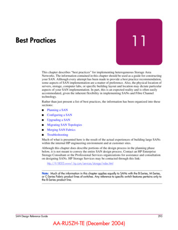
SAN ExtensionPorts 0 through 3 are capable of supporting distances up to 20 km at 1 Gbps and up to 10 km at2 Gbps per second.Ports 4 through 23 do not have enough buffer-to-buffer credits to support long wave SFPtransceivers and are limited to the short wavelength SFP transceiver limits of 500 meters at 1Gbps or 300 meters at 2 Gbps.10-100km Port settingIn order to maintain line speed performance of close to full Fibre Channel speed for extendedlines over 10 km it is necessary to configure the applicable ports for 10-100km setting. Usingthe High Availability Fabric Manager (HAFM) select the configure ports menu option andthen click on the 10-100 km box for the applicable ports. This will increase the number ofbuffer-to-buffer credits from 16 to 60 for the selected port.Figure 64: HAFM Configure Ports for 10-100 km settingSAN Design Reference Guide229
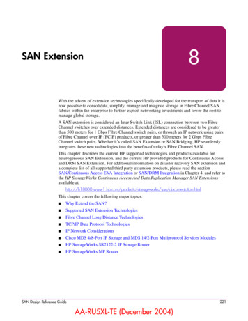
SAN ExtensionTCP/IP Data Protocol TechnologiesFibre Channel over Internet Protocol (FCIP)FCIP is a protocol that encapsulates Fibre Channel frames into IP packets and tunnels themthrough an existing IP network infrastructure to transparently connect two or more SANfabrics together. The IP tunnel acts as a dedicated link to transmit the Fibre Channel datastream over the IP network, while maintaining full compatibility with the Fibre Channel SAN.FCIP Gateways perform Fibre Channel encapsulation process into IP Packets and reverse thatprocess at the other end.Fibre Channel switches (B-series and M-series) connect to the FCIP gateways through anE Port for SAN fabric extension to remote locations. C-series switches use plug-in modulesfor FCIP functionality.A tunnel connection is set up through the existing IP network routers and switches acrossLAN/WAN/MAN.This example shows a configuration that connects Fibre Channel SANs using an InternetProtocol (IP) intersite link.Switch AFCIPequipmentFCIPequipmentSwitch BIPFigure 65: Connecting Fibre Channel SANs with an IP linkUsing Internet Protocol over an IP-based network, FCIP can link sites over any extendeddistance. Local SANs are connected through an IP network to create an extended SAN. AnFCIP gateway is used at each end of the intersite link. Each FCIP gateway box encapsulatesreceived Fibre Channel frames into IP packets for transmission over the IP network. Similarly,the FCIP box extracts the original Fibre Channel frame from received IP packets andretransmits them to the destination Fibre Channel node. The FCIP boxes also handle IP-levelerror recovery.FCIP Products supported for Heterogeneous SAN ExtensionThe HP StorageWorks SR2122-2 IP Storage Router provides heterogeneous SAN FCIPextension support on HP Series B-Series, C-Series, and M-Series Fibre Channel switches.The HP StorageWorks MP Router provides heterogeneous SAN FCIP extension support onHP B-Series Fibre Channel switches.The Cisco MDS 4/8-Port IP Storage Module and MDS 14/2-Port Multiprotocol ServicesModule are supported with C-Series product line switches.The SAN Valley SL700/SL1000 IP-SAN Gateways are supported with B-Series and M-Seriesproduct line switch models for heterogeneous SAN FCIP extension. Please read themanufacturers documentation for further configuration details.230SAN Design Reference Guide
SAN ExtensionIP Network ConsiderationsConsiderations Relevant to Using the Existing IP NetworkThe ability to use your existing network with FCIP depends on the type of storage I/O youplan to do and the traffic already existing on your current network. The key consideration iswhether you have enough unused/available bandwidth from your network to continue thecurrent network load, accommodate future growth, and handle FCIP SAN load demands.Table 51: IP Network Issues to ConsiderStorage I/O TypeUse Existing IP Network?FactorsMirrored I/O or continuousI/O throughput over the FCIPintersite link.A separate network isrecommended.For peak performance foryour current network, and forpeak Storage I/Operformance a separatenetwork is recommended.Data Migration or AdhocData UpdatesThe use of your existingnetwork may be possible.Data migration is a one-timemovement of data for upgradeor maintenance purposes.Adhoc Data Updates is moreof a ‘burst’ of data from onesite to another for remotebackups, database contentdelivery, etc.It is possible to use yourexisting network, however thenetwork performance may besignificantly affected.Network SpeedsIn general, the FCIP equipment supports Ethernet speeds of 10/100 Mb/s, and 1 Gbps (GigabitEthernet). The network connection should be selected to match the amount of data to betransferred.The speed of light through fibre is approximately 200,000 km per second or 5 microseconds totravel one km.Network Distance ConsiderationsThe HSG80 controller uses SCSI protocol to manage the storage devices. Before a SCSI I/Ocan be transmitted, it must be encapsulated into Fibre Channel frames. Because of SCSIprotocol, a minimum of 4 trips over the long-distance link is required.These trips conceptually:1. Tell the remote site you want to transmit data.2. Wait for the acknowledgment from the remote site.3. Send the data to the remote site.4. Wait for the acknowledgment from the remote site.SAN Design Reference Guide231
SAN ExtensionWhen sending data over fiber, the one-way transmission time is approximately 5 microsecondsper km of optical cable. Since a minimum of four trips is required for each SCSI data transfer,this translates to a total transmission delay per command of 20 microseconds per km, or about32.2 microseconds per mile. For example, if a remote site is located 150 miles away from thelocal site, the total time will be 4,830 microseconds (4.83 milliseconds) for every data transfer.Since a typical I/O operation on a non-DRM configuration with write-back cache takesapproximately 500 microseconds, long distances can have a significant effect on performance.Note: The above calculations for a link of 150 miles do not include any latency induced by theFC-to-IP conversions, or latency of the routers and switches in the network.Additional I/Os, either from additional LUNs on the same controller or from a differentcontroller, will require additional bandwidth. Care must be taken to understand this principle.Adding bandwidth to a given link at a given distance will not increase the time it takes tocomplete an I/O operation. It will, however, allow you to add additional I/Os from differentLUNs, thereby consuming the available bandwidth.Conversely, if enough bandwidth is not given to a link, then the number of I/Os per second willdecrease, possibly to the point of failureNote: The time it takes an I/O to complete an operation is more complex than the above example,and there are additional factors involved with this calculation. This discussion is an attempt to helpyou understand the importance that distance latency has on the time it takes to complete an I/Ooperation.232SAN Design Reference Guide
SAN ExtensionNetwork Distance/Latency Example Calculations1. 1.0 MB LinkLink Bandwidth: 1.0 MB/sWrite size: 8 KBAvailable bandwidth divided by size of I/O equals maximum I/Os per second:1.0 MB/s 125 I/Os per second8 KB per I/O2. 50 Miles of LatencyDistance: 50 miles (80 km)Latency: 8 µs/mile (5 µs/km)Write size: 8 KBLatency for 1 I/O per mile: 4 trips * 8 µs/mile 32 µs per mileLatency for 1 I/O at 50 miles: 50 miles * 32 µs/mile 1.6 ms per I/OReciprocal of total latency indicates maximum I/Os:1.0 625 I/Os per second1.6 ms per I/OI/O’s multiplied by size of I/O bandwidth used:625 I/O per second * 8 KB per I/O 5 MB/s3. 150 Miles of LatencyDistance: 150 miles (241 km)Latency: 8 µs/mile (5 µs/km)Write size: 8 KBLatency for 1 I/O per mile: 4 trips * 8 µs/mile 32 µs per mileLatency for 1 I/O at 150 miles: 150 miles * 32 µs/mile 4.8 ms per I/OReciprocal of total latency indicates maximum I/Os:1.0 208 I/Os per second4.8 ms per I/OI/Os multiplied by size of I/O bandwidth used:208 I/O per second * 8 KB per I/O 1.6 MB/sSAN Design Reference Guide233
SAN ExtensionIn summary, when an IP Network is used in a situation where the local and remote sites arelocated many miles apart, the speed of light through fiber may cause unacceptable delays inthe completion of an I/O transaction. Increasing the amount of available bandwidth cannotsolve this problem. Careful consideration must be given to these factors when matching yourneeds and wants to a particular application.IP Network Best PracticesCurrently most IP networks do not manage bandwidth to each individual connection. As trafficincreases due to other demands on the network, bandwidth can be robbed from the FCIPIntersite Link The following techniques can be used to minimize this effect: Create virtual private networks (VPNs) with Quality of Service (QoS) through premiserouters for the FCIP circuit. Create separate physical networks. Guarantee the bandwidth using a third-party router/QoS vendor.As mentioned, distance has a dramatic effect on the amount of work that can be done across alink. Therefore, site planning should include: Using the shortest possible distance between remote sites. Minimizing the amount data transferred over the FCIP link. Designing a plan to add additional storage I/O that will not impact normal data traffic. Consider additional controller pairs to effectively use available bandwidth.Cisco MDS 4/8-Port IP Storage and MDS 14/2-Port Muliprotocol Services ModulesThe Cisco MDS 4/8-Port IP Storage and MDS 14/2-Port Muliprotocol Services modulesextend the reach of Fibre Channel SANs by using open-standard, IP-based technology. Theswitches connect separated SAN islands using Fibre Channel over IP (FCIP). They integrateseamlessly into the C-Series MDS 9000 Family, and support the full range of featuresavailable on other switching modules, including VSANs, security, and traffic management.The MDS 4/8-Port IP Storage and MDS 14/2-Port Muliprotocol Services Modules can be usedin the C-Series 9500 and 9200 families of switches and have 4, 8 and 2 Gigabit Ethernet portsrespectively.234 FCIP-FCIP transports Fibre Channel frames transparently over an IP network between twoC-Series MDS 9000 Family switches. Figure 66 depicts the FCIP scenarios in which theIPS module is used. Simplifies data protection and business continuance strategies by enabling backup, remotereplication, and disaster recovery over WAN distances using open-standard FCIPtunneling. Improves utilization of WAN resources for backup and replication by tunneling up to 3virtual Inter Switch Links (ISLs) on a single Gigabit Ethernet port. Reduces SAN complexity by eliminating the need to deploy and manage a separate remoteconnectivity platform. Preserves C-Series MDS9000 Family enhanced capabilities including VSANs, advancedtraffic management, and security across remote connections.SAN Design Reference Guide
SAN ExtensionFCFabric"Control" TCPconnectionIPnetwork"Data" TCPconnectionFCFabricFCFabricFigure 66: FCIP ScenariosTable 52: Supported SFPsOpticsMediaDistance1-Gbps—SX, LC SFP50/125 micron multimode500 m1-Gbps—SX, LC SFP62.5/125 micron multimode200 m1-Gbps—
SAN Design Reference Guide 221 AA-RU5XL-TE (December 2004) SAN Extension 8 With the advent of extension technologies specifically developed for the transport of data it is now possible to consolidate, simplify, manage and integrate storage in Fibre Channel SAN fabrics within the enterprise to further exploit networking investments and lower the .