Transcription
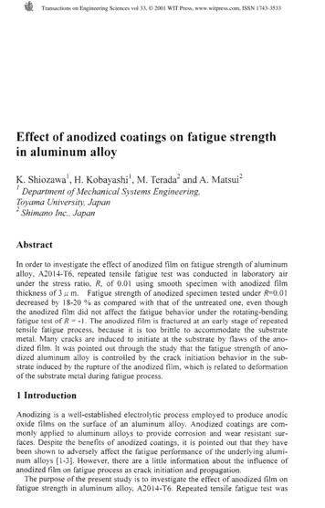
Transactions on Engineering Sciences vol 33, 2001 WIT Press, www.witpress.com, ISSN 1743-3533Effect of anodized coatings on fatigue strengthin aluminum alloyK. hiozawa',H. KobayashiL,M. erada'and A. a t s u i '' Departnzent of Mechanical Systems Engineering,Toyama University, JapanShimano Inc. JapanAbstractIn order to mvestigate the effect of anodized film on fatigue strength of aluminumalloy, A2014-T6. repeated tensile fatigue test was conducted in laboratory airunder the stress ratio, R. of 0.01 using smooth specimen with anodized filmthickness of 3 p m. Fatigue strength of anodized specimen tested under R 0.01decreased by 18-20 % as compared with that of the untreated one. even thoughthe anodized film did not affect the fatigue behavior under the rotating-bendingfatigue test of R - I . The anodized film is fractured at an early stage of repeatedtensile fatigue process. because it is too brittle to accommodate the substratemetal. Many cracks are induced to initiate at the substrate by flaws of the anodized film. It was pointed out through the study that the fatigue strength of anodized aluminum alloy is controlled by the crack initiation behavior in the substrate induced by the rupture of the anodized film, which is related to deformationof the substrate metal during fatigue process.1 IntroductionAnodizing is a well-established electrolytic process employed to produce anodicoxide films on the surface of an aluminum alloy. Anodized coatings are commonly applied to aluminum alloys to provide corrosion and wear resistant surfaces. Despite the benefits of anodized coatings, it is pointed out that they havebeen shown to adversely affect the fatigue performance of the underlying aluminun1 alloys [l-31. However, there are a little information about the influence ofanodized film on fatigue process as crack initiation and propagation.The purpose of the present study is to investigate the effect of anodized film onfatigue strength in aluminum alloy, A2014-T6. Repeated tensile fatigue test was
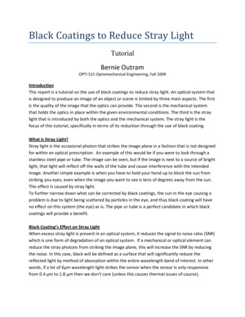
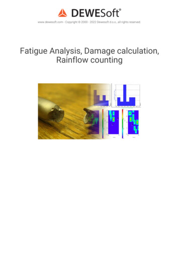
Transactions on Engineering Sciences vol 33, 2001 WIT Press, www.witpress.com, ISSN 1743-3533conducted in laboratory air using smooth plate specimen with anodized tilmthickness of 3 p m. Based on the experimental results, and observation of fracturesurface and failure of anodized film during fatigue process, fatigue fracturemechanisms of anodized aluminurn alloy was discussed.2 Experimental procedures2.1 Testing material and specimenThe material used in this study was wrought aluminurn-cupper alloy, A2014. Thechemical composition (mass %) of this alloy is 0.39 Fe, 4.82 Cu, 1.05 Si, 0.93Mn, 0.64 Mg and bal. Al. The material was hot-forged followed by extrusion to arod with 25 mm diameter and given a solution heat treatment at 778 K for 9 ks,was water-quenched, and then artificially aged for 28.8 ks at 443 K. The mechanical properties of the material after the T6 heat treatment are as follows;0.2 % proof stress D,, 418 MPa, tensile strength a, 486 MPa, elongation6 20.8 %, Vickers hardness HV 167, and grain size h 5 8p m.The specimen for axial fatigue testing was machined into smooth-plate geometry of dimensions as 12 mm long by 6 mm constant width and 3 mm thicknessgauge section. And also, hourglass shaped specimen for cantilever-type rotating-bending fatigue testing was machined with a 8 mm minimum gauge diameter.Surface of the specimen was mechanically polished with emery paper and subsequently rapped with of 3 p m diamond-paste prior to anodizing. The sulfuric acidanodizing process was employed and anodic oxide film with thickness of 3 p mwas coated on the specimen surface. Vickers hardness of the anodized layer was450 and essentially hard as compared with that of substrate material. Residualstresses in the anodized specimen was measured by the X-ray method in whichthe diffraction plane is Al(3 10) by Cr-K@.The compressive residual stress ofabout 5.5 MPa was measured on the rapped specimen surface. On the other hand,the tensile residual stress of about 1.5 MPa was on the substrate aluminum alloybellow the anodized film.2.2 Testing MethodFatigue tests were performed in air and laboratory atmosphere. Axial fatigue testsfor plate specimens were conducted using sinusoidal waveform at the frequencyof 20 Hz. The stress ratio (minimum stress to maximum stress) R was 0.01. Rotary bending fatigue tests for the hourglass shaped specimens were performedusing cantilever-type rotating bending fatigue machine operating at 1780 rpm Cf 29.7 Hz). By the nature of the rotary bending test, R was -1.3 Experimental results and discussions3.1 S-N curves of anodized specimensFigure 1 shows the S-N curves obtained from the axial repeated tensile fatiguetests. R 0.01. It can be seen from this figure that the anodized coating decreased
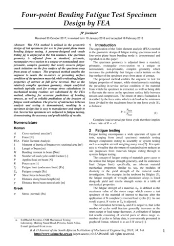
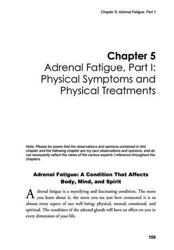
Transactions on Engineering Sciences vol 33, 2001 WIT Press, www.witpress.com, ISSN 1743-3533A2014-E-T6Untreated0 Anodizedb,350R O.Ol.-l50 L I o41 o5o611 o7Number of cycles to failure Nf ,cyclesFigure 1 : S-iV curves obtained under repeated tensile fatigue test, R O.O IL,;i-'1Cantliever-type rotatmg-bendmg fatigueloot .,',,',,,,,,,,',,,,,,,.'' ' . , , , . ' l'10310410510610'Number of cycles to failure N ,cycles,Figure 2: S-,V curves obtained under rotating-bending fatigue test, R - l .the fatigue strength at all lifetime. Life reduction at low stress level is slightlygreater than that at high stress level. The fatigue strength of untreated specimen at,, 250 MPa and that of anodized specimen was a,,, 20010' cycles was aMPa. Therefore, decrease in fatigue strength due to anodizing was 20 % forA20 14-T6.The results for cantilever-type rotating-bending fatigue testing (R - I ) of anodized and untreated specimens are shown in Fig. 2. No difference is found in fatigue strength between both specimens at high stress amplitude level and shortlife region. But the anodized coating specimen shows slightly greater fatiguestrength compared to the untreated one at low stress amplitude level. Possiblethreshold behavior was observed around 180 MPa, leading to run-out in the caseof the anodized specimen and increase in fatigue strength of 20 % showed ascompared with untreated specimen. A mechanism for the increase in fatiguestrength of coating specimen is expected that the hard surface layer can act asbarriers to the egress of dislocations, causing dislocation pile-ups and formationof crack nuclei beneath the coating film. This behavior has been reported by oneof the authors through the studies about the fatigue tests of TiN coated carbonsteel [4-71. It is of interesting that the fatigue strength of anodized coating specimen shows the dependency on the applied stress ratios.
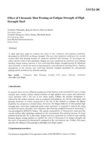
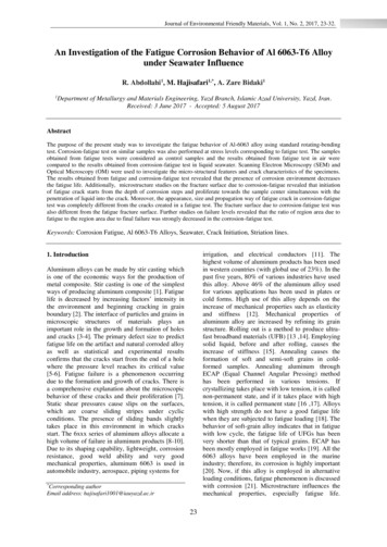
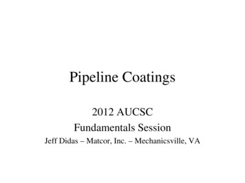
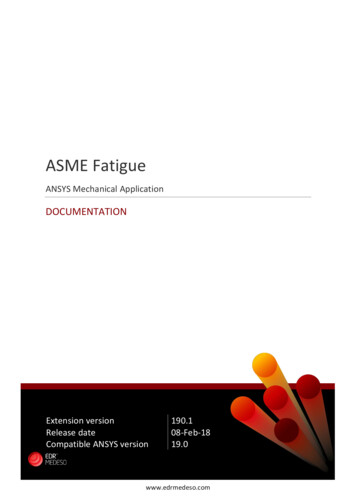
Transactions on Engineering Sciences vol 33, 2001 WIT Press, www.witpress.com, ISSN 1743-35333.2 FractographyTo clarify the decrease in fatigue strength of anodized coating specimen under theR 0.01, fracture surface was observed by a SEhl. Figure 3 shows a typical exampleof the crack initiation site on fracture surface of untreated specimen. '4 facet wasobserved at crack initiation site, at which a crack caused with the crystal slip beneath the specimen surface. An example of fracture surface on anodized specimenwas shown in Fig. 4. Ratchet marks on the fracture surface can be found in Fig. 4(a),which are the result of multiple fatigue crack origins. From the observation ofhigher magnification as shown in Fig. 4(b), a crack is formed due to the crystal slipas same as Fig. 3. Figure J(c) shows the results observed both of fracture surfaceand specimen surface, that is, the observation was made from the 3OCinclineddirection. Initiated cracks at the multiple crack initiation sites propagated independently and coalesce the cracks in neighborhoods. Then crack propagation pathon the surface of coating specimen presents a zigzag pattern.Figure 5 shows the experimental relationship between applied maximum stressand number of cracks on the fracture surface. The number of cracks formed on thefracture surface of anodized specimens is larger than that of the untreatedFigure 3: A tqpical SEM observation of crack initiation siteon the untreated specimen.Figure 4: Typical example of fracture surface on anodlzed coatmg specimen.
Transactions on Engineering Sciences vol 33, 2001 WIT Press, www.witpress.com, ISSN 1743-3533A2014-E-T6IUntreatedC.-m.-0 AnodizedMaximum stress f gax, MPaFigure 5 : Experimental relationslllp between number of crack initiationsite on fracture surface and applied maximum stress.specimens, in which only one or t n o cracks exist. And also, it is recognized fromthis figure that the number of crack initiation sites depends on applied stress andincreases as increasing applied stress. From the observation of fracture surfacetested under the rotating-bending fatigue, no difference was observed in the number of crack initiation sites bethveen anodized and untreated specimens. Therefore:It is suggested that the decrease in fatigue strength of anodized coating specimen iscaused by the increase in crack initiation sites and crack propagation rate due tocoalescence to cracks.The surface of fatigue-ruptured specimen was observed. Figure 6 shows theresults obsened by a SEM on anodized coating specimen tested under R 0.01. Alot of flaws of coating film pelpendicular to the stress axis lvere observed. On theother hand. any tlaws could not be found on the coated specimen surface rupturedunder the fatigue test of R -l and leaded to run-out under the R 0.01. Figure 7shows an example of cracks initiated on substrate metal accompanying a flaw ofanodized coating film. From this figure. it is understood that flaws developed in thefilm during fatigue process act as stress raisers, and can thus contribute to initiationsites for fatigue crack and fatigue failure.t-----,StressFigure 6: SEM obsenation of fracture on anodized coating filmafter fatigue test.
Transactions on Engineering Sciences vol 33, 2001 WIT Press, www.witpress.com, ISSN 1743-3533Flaw onanodized filmnFigure 7: An example of crack initiation on substrateaccompanying at flaw of anodized film.3.3 Rupture behavior of anodized film3.3.1 Static tensile testBecause that anodized coating films are hard and brittle, the films will readilyrupture when deformed. Static tensile test of anodized coating specimen was performed and rupture behavior of coating film was discussed. Figure 8 shows theexperimental relation between flaw density on the coating film and applied staticstress, or total tensile strain of the specimen, where flaw density was defined as thenumber of flaws per rnillimeter along the axial direction. It was found that flaws oncoating film occurred at the applied tensile stress of 360-390 MPa and the totaltensile strain of 0.5-0.55 %, and that they increased with the stress or strain.From the comparison between the tensile stress occurring the flaw of coating filmand S-iV curve in Fig. 2. all applied stress amplitudes in rotating-bending fatiguetest are bellow the rupture stress of coating film. Therefore. coating film does notrupture during fatlgue process tested under R -l and no fatigue debit to anodizedApplied stress f 3 MPaTensile strain f &O/OFigure 8: Change in tlaw density of anodized coating film during statictensile test.
Transactions on Engineering Sciences vol 33, 2001 WIT Press, www.witpress.com, ISSN 1743-3533anodized specimen is observed. On the other hand, same discussion can not applied to the results obtained from the repeated tensile fatigue tested under R 0.01(see Fig. l ) , because that decrease in fatigue strength occurred at the appliedmaximum stresses bellow the critical stress formed flaws of film.3.3.2 Repeated tensile fatigue testTo discuss the rupture behavior of anodized coating film during fatigue process.the surface of coating specimen interrupted fatigue test was observed by a SEM.Figure 9 shows the experimental relationship between flaw density on the coatingfilm and fatigue life fraction, N/Nf, obtained from the fatigue test under R 0.01.Flaws on the film were observed at ,ViNf of 0.15-0.25 and flaw density increasedwith stress cycling. It should note in this figure that applied stresses in experiments are bellow the static tensile stress formed the flaws of film and flaw initiation life depends on applied stress. Crack length of about 50 p m was observedon untreated specimen surface at Nifi of 0.3 1. From the experimental results. it isconsidered that fatigue crack initiation of coated specimen induced by the flaw offilm will occur at an early stage of fatigue compared with untreated specimen.This fact was only seen in the case of repeated tensile fatigue of R O.Ol but notfor rotating-bending fatigue of R - l . Rupture of coating film will be related to thedeformation of substitute metal during fatigue process.EEA2014-E-T6Anodized220m80GiL10c&0.21, , , , ,0.4 0.6 0.8Life fraction NIN,Figure 9: Change in flaw density of anodized film formed duringfatigue process.3.4 Cyclic deformation behaviorIn order to discuss the effect of cyclic deformation on rupture of coating film,deformation behavior of the specimen during fatigue process was measured bystrain-gage method. Figure 10 shows the variation in total strain of the specimenduring fatigue, which includes a cyclic and ratchet strain, obtained from the repeated tensile fatigue testing. It can be seen from this figure that the total strain
Transactions on Engineering Sciences vol 33, 2001 WIT Press, www.witpress.com, ISSN 1743-353310,'11'1l',,0.1 0.2 0.3 0.4 0.5Life fraction NIN,,,,,0.6 0.7Figure 10: Change in total strain during repeated tensile fatigue process.increases with stress cycling and reaches to steady state condition in 30-40 % oflife to failure. In this figure, rupture strain of anodized coating film, 0.5-0.55 %.obtained from static tensile test mentioned above, is shown with dotted lines. Thetotal strain of the specimen increases with cycling and comes up to the rupturestrain of coating film in 5-20 % of life to failure, depending on applied stresses.An exception is in the case of applied stress of 200 MPa, because that this specimen leaded to run-out and no flaws of coating film observed on the specimensurface after testing.Figure 1 1 shows the cyclic stress-strain curve obtained from Fig.10. Thestrains in this figure were obtained at 20 96 of life to failure, because the ruptureof coating film occurred in an early stage of the fatigue process. It can be seenfrom this figure that the strain formed during fatigue is larger than that occurredduring static tension at the same applied stress.500.50.1Total strainE , ,1%Figure I l : Cyclic stress vs. strain curve obtained at iV/Nf 0.2 underrepeated tensile fatigue test.
Transactions on Engineering Sciences vol 33, 2001 WIT Press, www.witpress.com, ISSN 1743-35333.5 Strain-based S-N curveFigure 12 shows the relationship between total strain and number of cycles tofailure of anodized coating specimens for the repeated tensile fatigue testing. Thetotal strain was calculated from the cyclic stress-strain curve obtained from theexperimental results mentioned before section. It can be clearly understood thatthe cyclic strain of anodized coating specimens with finite fatigue life is abovethe rupture strain of coating film and infinite fatigue life of the coating specimenis defined as the upper limit of stress at which rupture of coating film does notoccur. From the experimental results and discussion, anodized coating film isfractured at an early stage of the fatigue process because it is too brittle to accommodate the substrate metal under testing conditions where large deformationoccurs or accumulates during fatigue. Thus, many cracks may be induced to initiate at the substrate by flaws of coating film and fatigue strength decreases as theresults. On the other hand, under testing conditions without large cyclic deformation of the specimen, crack initiation is delayed by hard coating film on thespecimen surface.A2014E-T6Anodized0.411 o4'1 o5'1 o6'1 o71Number of cycles to failure Nf ,cyclesFigure 12: Relationship between total strain and number of cycles tofailure of anodized coating specimen.4 ConclusionsThe following conclusions were obtained from the fatigue tests of anodized coating wrought A20 14-T6 aluminum alloy.(1) Anodization of the specimen gives reduction of about 20 % in fatigue strengthunder the testing condition of R O.O 1, that is, repeated tensile fatigue.(2) However. the eff'ect of anodized coating on fatigue strength does not find athigh stress amplitude range and fatigue strength of anodized coating specimenat 10'cycles increases about 20 % compared with uncoated specimen for thecantilever-type rotating-bending fatigue test. R - I . Fatigue strength of anodized coating specimen shows the dependency on applied stress ratio.
Transactions on Engineering Sciences vol 33, 2001 WIT Press, www.witpress.com, ISSN 1743-3533(3) Anodized coating film is ruptured at total tensile strain of 0.5-0.55 % underthe static tensile test.(4) Decrease in fatigue strength of anodized coating specimen is caused by formation of many cracks at an early stage of fatigue process induced by theflaws in the film, which act as stress raisers.(5) The fatigue strength of anodized coating specimen can be explained by thedeformation behavior during fatigue process. Accumulated strain of the substrate during cycling controls the fracture of coating film and flaws developedin the film contribute to crack initiation for fatigue failure.References[ l ] Cree, A.M. and Weidmann, G.W., Effect of anodized coatings on fatigue crackgrowth rates in aluminium alloy, Surjace Engng, 13- l , pp.5 1-55, 1997.[2] Rateick, Jr R.G., Binkowski, T.C. and Boray, B.C., Effect of hard anodizedthickness on the fatigue of AA6061 and C355 aluminium, Jour /Water: Sci.Letter, 15, pp.1321-1323, 1996.[3] Cree, A.M., Weidmann, G.W. and Hermann, R., Film-assisted fatigue crackpropagation in anodized aluminium alloys, Jour: iblater: Sci. Letter, 14,pp.1505-1507, 1995.[4] Shiozawa, K., Nishino, S. and FIanda, K., 'The effect of applied stress ratio onfatigue strength of TiN-coated carbon steel, JSME Inter. Jour., Series I , 35-3,pp.347-353, 1992.[5] Shiozawa, K., Tomosaka, T., Han, L. And Motobayashi. K., Effect of flaws incoating film on fatigue strength of steel coated with titanium nitride. JSMEInter. Jour., Series I , 39-1, pp.142-150, 1996.[ 6 ] Shiozawa, K., Some affecting factors for fatigue strength of ceramics coatingsteel, Surface Treartnent, ed. M.H. Aliabadi and C.A. Breddia, ComputationalMech. Pub., pp. 227-236, 1997.[7] Shiozawa, K., Effect of coating thin film on fatigue strength of materials, Fatigue '99, ed. X.R. Wu and Z.G. Wang, Higher Edu. Press, 3, pp. 1913- 1920.1999.
Figure 2: S-,V curves obtained under rotating-bending fatigue test, R - l. the fatigue strength at all lifetime. Life reduction at low stress level is slightly greater than that at high stress level. The fatigue strength of untreated specimen at 10' cycles was a,, 250 MPa and that of anodized specimen was a,,, 200 MPa.