Transcription
L0002 Rev. DSensit I Glass Front VendorOperation and Service ManualModels 35 (Snack), 39 (Snack),VCB (Visi-Combo), VCF (Visi-Diner and Milk)Automated Merchandising Systems Inc.109 West Burr Blvd.Kearneysville, WV 25430Phone 304-725-6921Fax 304-725-6983E-mail ams@intrepid.net
Sensit I Glass Front VendorTable of Contents1General Information1.1Introduction1.2Model Identification1.3Specifications1.4Standard Helix Configurations Available1.4.1AMS39 Models1.4.2AMS35 Models1.4.3AMS Visi-Diner1.4.4AMS Visi-Combo1.4.5AMS Milk11123345672Safety2.12.2888899991010Commitment to SafetyHazards2.2.1High Voltage Contact2.2.2Improper Grounding2.2.3Fan Contact2.2.4Helix Motion and Jamming2.2.5Refrigerant Release2.2.6Vendor Tipping2.2.7Other Hazards3Theory of Operation3.1Sensit System3.2Refrigeration System1111114Setup and Installation4.1Inspection4.2Connecting Power4.2.1Checking the Outlet (US & Canada)4.2.2Checking the Outlet (Outside US & Canada)4.2.3Electrical Service Requirements for CECompliance4.2.4Requerimiento de Servicio Eléctrico paraCertificación CE4.2.5Les Utilites electriques necessaire pourconformement aux regles CE1212121212124.34.2.6Installing the Power Cord and CoverSet-Up4.3.1Mounting and Connecting Bill Validators andCard Readers4.3.2Mounting and Connecting Coin Mechanism121314151515i
4.4ii4.3.3Test Loading4.3.4Installing Price Labels4.3.5Setting PricesOn-Site Installation4.4.1Remove Shipping Boards4.4.2Choosing a Location4.4.3Leveling the Vendor4.4.4False Leg Installation4.4.5Calibrating the Sensor4.4.6Initial nsor Errors5.2Health and Safety Errors5.2.1Out of Order-1 (Temperature Exceeded)5.2.2Out of Order-2 (Time Exceeded)5.2.3Out of Order-3 (Switch Error)5.3Testing the H & S Function of the Machine5.4Machine Errors5.4.1JAM MOTOR5.4.2DOORSWITCH5.4.3SEL STUCK5.4.4CHANGER5.4.5BILL VAL5.4.6CARDREADER5.4.7BT DT (Bottle Sensor)5.5Water Formation in the Cabinet5.6Trouble Shooting Chart20202021212122232323242424252525256Service and Maintenance6.1Replacing the Control Chip6.2Cleaning the Refrigeration Unit6.3Cleaning the Vendor6.4Cleaning the Plastic Door Liner6.5Lubrication2828293030307Major Components7.1Control Board7.2Vend Sensor7.3Door7.4Rails7.5Trays7.6Electrical Panel7.7Refrigeration System7.8Ventilation System3131323233333334358Service Mode8.1Change3535
8.28.38.48.58.6Tube FillTest VendPriceAccounting DataOptions8.6.1Bill Escrow8.6.2Force Vend8.6.3No Cheat8.6.4Lotto8.6.5Calibrate Sensor8.6.6Banner Messages8.6.7Temperature8.6.8Refrigeration Temperature Setting8.6.9Bill Changer8.6.10 Serial Number8.6.11 Vend Delay8.6.12 “G” Tray SetupSpace To 38393939393939394040419Tray Adjustments9.1Snack, Candy, and Food Tray Removal and Installation9.2Bottle Tray Removal and Installation9.3Bottle Tray Helix Replacement9.4Tray Positioning9.5Tray Configuration9.6Large Bag Vending Instructions9.7Pusher Bar Installation9.81.5” Helix Tray Adjustment and Loading9.8.1General Information9.8.2Tray adjustment and loading424242434244444546464610Wiring Diagram4711DEX Field Supported5112Optional Equipment5213Warranty538.78.88.98.10iii
iv
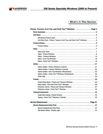
1. GENERAL INFORMATION1.1 IntroductionThe Automated Merchandising Systems Sensit I Snack, Visi-Combo, Visi-Diner and Milkare vending machines with high capacity and versatility. These various models provide for a widerange of product vending. Note: All food products are to be pre-packaged. AMS machines aredesigned, tested, and built to provide years of reliable, low-maintenance service in an indoorenvironment. They have full electronic control with Dex data capabilities. They each feature anelectronic vend sensing system coupled with an electronically controlled vend mechanism to assurereliable product delivery. The refrigeration unit (optional) is designed for consistent cooling andreliability. Many other features and components of the AMS line of vending machines are describedin detail in the following sections of this manual.Please note; It is our intent to assist our customers with up-to-date documentation, however, thismanual may not reflect all changes and may be subject to change without notice.1.2 Model IdentificationWhen requesting service, replacement parts or technical assistance, reference the VendorSerial Plate (Figure 1). It is located on the inside of the upper left or right of the window, or on theoutside of the main door on the lock side. The information contained on this plate is necessary todetermine what parts, kits, or maintenance should be applied to your specific model.Figure 1. Vendor Serial PlateModel NumberAMS 39 - 6 40ManufacturerCabinet WidthNo. of Trays*No. of Selections*Example: AMS39-640 means it is an Automated Merchandising Systems snack vendor, 39” wide,with six (6) trays and forty (40) positions for different products.*The dash number is dropped for Food, Bottle and Milk vendors and is replaced with ‘VCF’ or‘VCB’.1
Serial Number and Date Code0203 - 1010 C 8Sequential Production NumberProduction Run Number Quarter (ABCD)YearExample: 0203-1010-C8 would be translated as machine number 203 on production run number1010 manufactured in the third quarter of 1998.1.3 SpecificationsOperating EnvironmentAMS vendors are designed for indoor use between 33 F (1 C) and 110 F (43 C). Maximumtemperature for vendors with perishable food is 100 F (38 C). The vendor should not be located in anarea where it may be subjected to a water jet or rain.Dimensions: AMS35SizeWeightCapacity33 3/4”W x 72”H x 36”D (89 cm x 183 cm x 91 cm)Approx. 567 lbs. (257 kg), 674 lbs. (306 kg.) w/chiller1152 units max./120 units min. (depending on helix configuration)Dimensions: AMS39SizeWeightCapacity39”W x 72”H x 36”D (99 cm x 183 cm x 91 cm)Approx. 644 lbs. (292 kg), 726 lbs. (329 kg.) w/chiller1440 units max./ 150 units min. (depending on helix configuration)Dimensions: VCBSizeWeight39”W x 72”H x 36”D (99 cm x 183 cm x 91 cm)Approx. 692 lbs. (314 kg)Dimensions: VCFSizeWeight39”W x 72”H x 36”D (99 cm x 183 cm x 91 cm)Approx. 738 lbs. (335 kg)Power RequirementsUnited States and Canada:International:Basic Unit:Refrigerated Snack:Visi-Combo:Visi-Diner/Milk:Refrigeration SpecificationRefrigerant - Snack:Refrigerant - Visi-Combo:Refrigerant - Visi-Diner/Milk:115 VAC, 60 Hz230 VAC, 50/60 Hz3 amps @ 115 VAC (345 watts)7 amps @ 115 VAC (805 watts)10.8 amps @ 115 VAC (1242 watts)10.8 amps @ 115 VAC (1242 watts)1/4 HP, R-134a, 7.2 oz. (.20 kg)½ HP, R-134a, 8.5 oz. (.24 kg)½ HP, R-134a, 8.5 oz. (.24 kg)Coin Mechanisms and Bill Validators SupportedAMS vendors will support all NAMA-approved Multi-Drop Bus (MDB) coin mechanisms, billvalidators and card readers. Where applicable, it will also support the “Executive Mechanism” CoinChanger.2
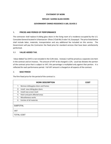
1.4 STANDARD HELIX CONFIGURATIONS AVAILABLE1.4.1 AMS39 12121212121515151212151515151515151515 15 18 18 18 18 18 24 24 2415AMS 39-630370 UNITS1515151515 15 15 15 18 18 24 24 24 2412AMS 39-635502 UNITS121212121215AMS 39-640617 UNITS10101010101010151515121215151512121212121818 18 18 18 18 18 18 18 18 1810121218 18 18 18 18 18 18 18 18 181818 18 18 18 18 18 18 18 1818 18 18 18 18 18 18 18 18 1818 18 18 18 18 18 18 18 1818 18 18 18 18 18 18 18 18 1818 18 18 18 18 18 18 18 18 1818 18 18 18 18 18 18 18 1815 15 15 15 18 18 24 24 24 2418 18 18 18 18 18 15 15 15 1518 18 18 18 18 18 15 15 1515 15 15 15 15 15 24 24 24 2415 15 15 15 15 15 24 24 24 24AMS 39-650839 UNITSAMS 39-655955 UNITS1212121212AMS 39-645731 UNITS15 15 15 15 15 15 15 15 15 1518 18 18 18 18 18 18 18 18 1818 18 18 18 18 18 18 18 18 1818 18 18 18 18 18 18 18 18 1818 18 18 18 18 18 18 18 18 1815 15 15 15 18 18 24 24 24 24AMS 39-6601060 UNITSAvailable Helix Sizes:2 ½ Inch (63mm)20139-077 Pitch, 2 5/8” (66mm) Opening20139-1010 Pitch, 1 7/8” (47mm) Opening20139-1212 Pitch, 1 5/8” (41mm) Opening20139-1515 Pitch, 1 1/4” (31mm) Opening20139-1818 Pitch, 1”(25mm) Opening20139-2424 Pitch, 3/4” (19mm) Opening4 Inch (102mm)20173-055 Pitch, 3 1/4” (82mm) Opening20173-077 Pitch, 2 1/2” (63mm) Opening20173-099 Pitch, 2”(50mm) Opening20139-1010 Pitch, 1 3/4” (44mm) Opening20173-1212 Pitch, 1 1/2” (38mm) Opening20173-1515 Pitch, 1 1/4” (31mm) Opening31815
1.4.2 AMS35 151515151518 18 18 18 18 18 24 2415AMS 35-624313 UNITS15151515 15 18 18 18 24 24 2418 18 18 18 18 18 18 1812AMS 35-628418 UNITS121212AMS 35-632508 UNITS101215151012121212121515121215151012121518 18 18 18 18 18 18 1815 15 15 15 24 24 24 2418 18 18 18 18 18 18 1818 18 18 18 18 18 18 1818 18 18 18 18 18 18 1818 18 18 18 18 18 18 1818 18 18 18 18 18 18 1818 18 18 18 18 18 18 1818 18 18 18 18 18 24 2418 18 18 18 18 24 24 2415 15 15 15 15 15 24 2415 15 15 15 15 24 24 24AMS 35-640682 UNITSAMS 35-644790 UNITS12121212AMS 35-636598 UNITS15 15 15 15 15 24 24 2418 18 18 18 18 24 24 2418 18 18 18 18 18 18 1818 18 18 18 18 18 18 1818 18 18 18 18 18 18 1818 18 18 18 18 18 18 18AMS 35-648885 UNITS4Available Helix Sizes:2 ½ Inch (63mm)20139-077 Pitch, 2 5/8” (66mm) Opening20139-1010 Pitch, 1 7/8” (47mm) Opening20139-1212 Pitch, 1 5/8” (41mm) Opening20139-1515 Pitch, 1 1/4” (31mm) Opening20139-1818 Pitch, 1”(25mm) Opening20139-2424 Pitch, 3/4” (19mm) Opening4 Inch (102mm)20173-055 Pitch, 3 1/4” (82mm) Opening20173-077 Pitch, 2 1/2” (63mm) Opening20173-099 Pitch, 2”(50mm) Opening20139-1010 Pitch, 1 3/4” (44mm) Opening20173-1212 Pitch, 1 1/2” (38mm) Opening20173-1515 Pitch, 1 1/4” (31mm) Opening
1.4.3 AMS Visi-Diner555555555555555777777777777777AMS 39-FOOD180 UNITSAvailable Helix Sizes:2 ½ Inch (63mm)20139-077 Pitch, 2 5/8” (66mm) Opening20139-1010 Pitch, 1 7/8” (47mm) Opening20139-1212 Pitch, 1 5/8” (41mm) Opening20139-1515 Pitch, 1 1/4” (31mm) Opening20139-1818 Pitch, 1”(25mm) Opening20139-2424 Pitch, 3/4” (19mm) Opening4 Inch (102mm)20173-055 Pitch, 3 1/4” (82mm) Opening20173-077 Pitch, 2 1/2” (63mm) Opening20173-099 Pitch, 2”(50mm) Opening20139-1010 Pitch, 1 3/4” (44mm) Opening20173-1212 Pitch, 1 1/2” (38mm) Opening20173-1515 Pitch, 1 1/4” (31mm) Opening5
1.4.4 AMS Visi-Combo1010151515121212121215 15 15 15 15 18 18 18 18 186666666666666666AMS 39-VISI-COMBO386 UNITSAvailable Helix Sizes:2 ½ Inch (63mm)20139-077 Pitch, 2 5/8” (66mm) Opening20139-1010 Pitch, 1 7/8” (47mm) Opening20139-1212 Pitch, 1 5/8” (41mm) Opening20139-1515 Pitch, 1 1/4” (31mm) Opening20139-1818 Pitch, 1”(25mm) Opening20139-2424 Pitch, 3/4” (19mm) Opening3 Inch (76mm)207634 Inch 73-1566 Pitch, 3 1/2” (88mm) Opening(Bottle / Milk Trays Only)5 Pitch, 3 1/4” (82mm) Opening7 Pitch, 2 1/2” (63mm) Opening9 Pitch, 2”(50mm) Opening10 Pitch, 1 3/4” (44mm) Opening12 Pitch, 1 1/2” (38mm) Opening15 Pitch, 1 1/4” (31mm) Opening
1.4.5 AMS 66666666AMS 39-Milk240 UNITSAMS 39-Milk288 UNITSAvailable Helix Sizes:3 Inch (76mm)207636 Pitch, 3 1/2” (88mm) Opening(Bottle / Milk Trays Only)7
2. SAFETY2.1 Commitment to SafetyAutomated Merchandising Systems Inc. is committed to designing and producing a safeproduct. As with all electrical or mechanical pieces of equipment, potential hazards exist. It is theintent of Automated Merchandising Systems, through this manual and service technician training, to alertindividuals who will be servicing our equipment to these potential hazards, and to provide basic safetyguidelines.To reduce the risk of serious injury or death, please read and follow all warnings in this manual.It is important that we point out that these warnings are not comprehensive. AutomatedMerchandising Systems can not possibly anticipate all of the ways that service may be conducted, nor allof the possible safety hazards that may result from service. Therefore at all times we urge you to bewareof hazards such as electrical shock, mechanical entrapment, and tipping a vendor during movement.Automated Merchandising Systems strongly recommends a commitment to safety on the part ofall servicing personnel or organizations. Only personnel properly trained in vendor servicing shouldattempt any service to the internal components of the vendor. It is important to point out thatAutomated Merchandising Systems has no control over the vendor once it leaves our factory.Maintaining the vendor in a safe condition is the sole responsibility of the owner.If you have questions concerning safety or service, or would like more information, pleasecontact the Automated Merchandising Systems Service Department at 304-725-6921 or e-mailams@intrepid.net.2.2 HazardsBelow are listed some specific hazards and safe practices to follow to avoid injury from thosehazards. This list can not possibly cover all hazards, therefore please remember to THINK SAFETYFIRST.2.2.1 High Voltage ContactAll vendors are designed to operate on a specific voltage, either single phase 115VAC 60Hz or220-240VAC 50-60Hz, depending on the country. The voltage is specified on the serial plate (seeModel Identification 1.2). High voltage areas include the electrical panel, the refrigeration unit and fans,and the fluorescent lamp. It is important to understand that contact with the high voltage wiring canresult in injury or death.1.2.3.4.8Always test the outlet for proper voltage, polarity and grounding before plugging inthe vendor.Always disconnect power to the vendor before servicing. Allow only fully trainedservice technicians to service the vendor if service must be performed with the poweron.Always keep electrical connections dry. Do not place the vendor in or near standingwater.Never use a worn or damaged power cord.
2.2.2 Improper GroundingSome electrical components have a green or green/yellow ground wire attached to agrounding point in the vendor. If it becomes necessary to remove a ground wire during service, notehow the wire is attached, including the locations of any washers. After servicing, make sure that thewires and washers are replaced exactly as they were. Note that the vendor will work normally withoutthe ground wires, but there will be a potential shock hazard from ungrounded components.1.2.Always test the outlet for proper grounding before plugging in the vendor.Always reconnect ground wires after servicing.2.2.3 Fan ContactSome vendors are equipped with electric fans, which can start automatically. These fans areguarded to prevent accidental contact. However, removal of guards or other components can leavethese fans exposed and create a physical hazard.1.2.3.4.5.6.Always disconnect power to the vendor before servicing.Always keep protective covers in place.Always wear hand and eye protection when servicing the vendor.Always keep hands, hair, loose clothing and tools away from moving parts.Never insert hands or tools into concealed areas.Always replace protective covers after service.2.2.4 Helix Motion and JammingEnergized vend motors can turn a helix with considerable torque, creating a possibleentrapment hazard. Also, turning helices may eject tools or other objects left on trays.A helix that is jammed or caught can store energy as it binds, which can cause it to twist or springoutward suddenly even if power is disconnected. Use caution when freeing a jammed helix.1.2.3.4.5.Always disconnect power to the vendor or control board before servicing the vendmotors.Always check for proper fit when loading products in the helices to avoid jamming.Always restrain the helix before freeing a jammed or caught helix.Always wear hand and eye protection when servicing the vendor.Always keep hands, hair, loose clothing and tools away from moving parts.2.2.5 Refrigerant ReleaseThe refrigeration system is pressurized and sealed at the factory. Puncturing or cutting anycomponent in the system will cause refrigerant gas and liquid to be propelled out of the system,creating an immediate physical hazard. Use caution to avoid accidentally opening the refrigerantsystem.It should also be noted that releasing refrigerant to the atmosphere is a federal crime andis punishable by law. Any service work requiring the system to be opened must be performed by alicensed technician using certified equipment. Unauthorized service to the sealed refrigerant systemmay void the warranty.1.2.3.Never puncture or cut any component in the refrigeration system.Always use licensed service technicians to service the refrigeration system.Always wear hand and eye protection when servicing the vendor.9
2.2.6 Vendor TippingThe empty weight of the vendor is approximately 576 to 800 pounds. A falling vendor cancause serious injury or death. Caution should always be taken to avoid dropping or tipping avendor.1.2.3.4.5.6.Never rock or tip the vendor.Never place the vendor in an inclined position, such as on a ramp or with all the legsnot on the same horizontal surface.Never place the vendor in a moving environment such as on a ship without properlysecuring it in place.Never place the vendor in a location where it may be struck by a vehicle.Never transport an unsecured vendor.Never attempt to lift or move the vendor by hand. Always use equipment with theproper load rating. Note that the weight listed in Specifications is empty weight.2.2.7 Other HazardsHazardous conditions can be created by improper use or service of the vendor.1.2.3.4.10Always reinstall any parts removed during service to their original locations.Never make unauthorized modifications to any part of the vendor.Always replace components that are worn, broken, or otherwise unfit for use.Never use unauthorized parts, or use parts for anything other than their intendedapplication.
3. THEORY OF OPERATION3.1 Sensit System The Sensit system is comprised of three elements; the emitter, the detector, and the control logic. Theemitter is a circuit board with a row of infra-red diodes located on one side of the hopper. A diffuserin front of the emitter redirects the light to create a plane of light across the top of the hopper. Thedetector is located on the opposite side of the hopper. It is composed of a circuit board attached to ahousing. The detector circuit board has two infra-red sensors that measure the intensity of the lightand relay the information to the control. The detector housing has a double parabolic mirror thatfocuses the light on the two sensors.The sensor must be calibrated so that the control recognizes the normal intensity of the light passingacross the hopper. The sensor should be calibrated whenever a sensor component is changed or thevendor is placed in a new location.The sensor can be manually calibrated in service mode by pressing 5 while in the OPTIONS function(see 4.4.5 Calibrating the Sensor).The sensor will automatically calibrate itself every 3 minutes in normal operation to account forchanges in environmental light and other variables.When the vendor is serviced with the door open, the sensor can become fogged up and the temperatureof the sensor can increase, particularly in hot or humid locations. After the door is closed, the sensorwill calibrate every minute for 60 minutes to allow for changes in the sensor temperature and changesin light intensity as the fogging clears off. In some situations, the vendor may not be able to venduntil the fogging has cleared. In these cases, the vendor will display “PLEASE MAKE ANOTHERSELECTION” and return the customer’s money. The money is returned in order to slow the processof making another selection, which gives the sensor more time to clear and begin operating correctly.This feature overrides the FORCE VEND option (see 8.6.2 FORCE VEND) during the 10 minuteperiod.When a selection is made, the control checks the operation of the sensor before vending the product.If the intensity of the light is not within 15% of the value measured during the last calibration, thecontrol will display “PLEASE MAKE ANOTHER SELECTION” and return the customer’s money(see 5.1 Sensor Errors).When a selection is made, the vend motor will begin to run. After several seconds, if no product fallsin the hopper, the motor will be stopped, the credit will be maintained and the customer will bedirected to “PLEASE MAKE ANOTHER SELECTION.”When the control measures a variation in the light intensity during the vend cycle, it recognizes that aproduct has fallen through the light into the hopper. The control stops the vend motor and removes thecredit.3.2 Refrigeration System The refrigeration system is operated through the electronic control board. A temperature sensor in thecabinet relays the current temperature to the control. If the temperature is above the setting that has been programmed in by the user (see 8.6.7Temperature Setting), the control sends a 24VDC signal to the refrigeration relay. The energizedrelay closes to complete the high voltage circuit that powers the compressor and the condenser fan. If the compressor should overheat, a thermal overload removes power to the compressor until it hascooled. When the temperature in the cabinet reaches 5 F cooler than the temperature setting, the control deenergizes the relay, which in turn breaks the circuit powering the compressor. The control will also shut off the compressor if the door is opened. This is to prevent the refrigerationunit from freezing up.After the compressor has shut down, the control will wait until the compressor has been shut down 3 minutesand if applicable, the door has been closed 10 seconds before restarting the compressor. The delay allowspressure in the system to equalize.4. SETUP AND INSTALLATION11
4.1 InspectionInspect the vendor carefully for shipping prior to signing the carrier’s delivery receipt. Checkfor dents on the top or sides of the vendor, bent legs, broken glass, or other damage on the exterior ofthe machine. Check the interior for components that may have been knocked loose or other damage.4.2 Connecting PowerPower to the vendor outlet must remain switched on for the vendor to operate.4.2.1 Checking the Outlet (US and Canada)Using a volt meter set to AC Volts, check the voltage between the positive (smaller) lug entryand the ground lug entry (or center screw on two-lug outlets). The reading should be between 103volts and 126 volts. Next, check the voltage between the negative (larger) lug entry and the ground.The reading should be 0 volts. If your results vary, contact a qualified electrician to correct the outletwiring before plugging in the vendor. Abnormal voltage, reversed polarity or improper groundingmay cause the vendor to malfunction or create hazardous conditions in the vendor, resulting inpossible injury, damage to the vendor, or fire. Never use an extension cord with the vendor.The power cord is shipped in the hopper on the inside of the door. The cord is supplied witha standard NEMA 3-wire plug. If there are no 3-wire outlets available for powering the vendor, agrounding adapter may be used to convert a 2-wire outlet to accept the 3-wire plug. The adapter musthave a ground tab or wire which must be fastened to the center screw of the outlet.4.2.2 Checking the Outlet (Outside the US and Canada)Consult a qualified electrician to check the outlet for proper polarity, voltage, and grounding.Check the serial plate on the side of the door to confirm the vendor is rated for the outlet voltage.4.2.3 Electrical Service Requirement for CE ComplianceThe following requirement applies only to models 39-VCB, 39-VCF, or other models using ½HP compressors and displaying the CE mark on the serial plate. If this requirement applies to yourvendor, you will see a similarly worded decal on the back of the vendor near the power cord.This requirement does not apply to any vendor using 120V service.ELECTRICAL SERVICE REQUIREMENT FOR CE COMPLIANCE:THIS EQUIPMENT IS INTENDED FOR USE ONLY IN PREMISES HAVING ASERVICE CURRENT CAPACITY OF AT LEAST 100A PER PHASE, SUPPLIED FROM ADISTRIBUTION NETWORK HAVING A NOMINAL VOLTAGE OF 400/230V. THE USERSHOULD DETERMINE IN CONSULTATION WITH THE SUPPLY AUTHORITY, IFNECESSARY, THAT THE SERVICE CURRENT CAPACITY AT THE INTERFACE POINTIS SUFFICIENT FOR THIS EQUIPMENT.4.2.4 Requerimiento de Servicio Eléctrico para Certificación CEEl siguiente requerimiento se aplica solamente a los modelos 39-VCB, 39-VCF, o a otrosmodelos que utilicen compresores de ½ HP y que muestren la marca CE en la placa de serie. Si esterequerimiento se aplica a su dispensadora, verá una calcomanía con una terminología parecida en laparte posterior de la dispensadora, cerca del cordón de corriente.Este requerimiento no se aplica a dispensadoras que utilizan un servicio de 120V.12
REQUERIMIENTO DE SERVICIO ELECTRICO PARA CERTIFICACIONCE:ESTE EQUIPO SE PUEDE UTILIZAR SOLAMENTE EN ESTABLECIMIENTOSQUE CONTENGAN UNA CAPACIDAD DE CORRIENTE DE SERVICIO DE POR LOMENOS 100A POR FASE, Y SUMINISTRADOS POR UNA RED DE DISTRIBUCION QUECONTENGA UN VOLTAJE NOMINAL DE 400/230V. EL USUARIO DEBERA CONSULTARCON UNA AUTORIDAD DE SUMINISTRO, SI ES NECESARIO, PARA VERIFICAR QUELA CAPACIDAD DE CORRIENTE DE SERVICIO EN EL PUNTO DE INTERFASE ESSUFICIENTE PARA ESTE EQUIPO.4.2.5 Les Utilites electriques necessaire pour conformement aux regles CELe suivant condition applique seulement à modèles 39-VCB, 39-VCF, ou autre modèles enutilisant ½ HP compresseur et montrer le CE sur l'en série plaque. Si cette condition s'applique à votrevendeur, vous verrez un decal de même exprimé sur le dos du vendeur près du cordon d'alimentation.Cette condition ne s'applique pas au service de 120V d'utilisation de vendeur.LES UTILITES ELECTRIQUES NECESSAIRE POUR CONFORMEMENTAUX REGLES CE:CET EQUIPEMENT NE DOIT UTILISER QUE SUR LES LIEUX AVEC UNECAPACITE DU COURANT AU MOINS 100A LA PHASE, FOURNIE A UN RESEAU DEDISTRIBUTION AVEC UN VOLTAGE NOMINAL DE 400/230V. LA PERSONNE QUI SEDETERMINER PENDANT UNE CONSULTATION AVEC L’ADMINISTRATION DUSECTEUR, S’IL FAUT, QUE LA CAPACITE DE COURANT AU POINT D’INTERFACEEST ASSEZ POUR CET EQUIPEMENT.13
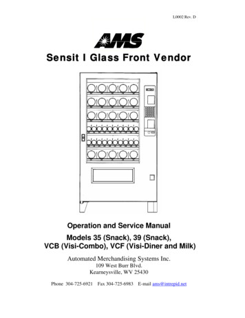
4.2.6 Installing the Power Cord and CoverTOOLS REQUIRED:Drill with 1/4” Socket Driver (Always wear eye protection when servicing vendor.)1. Plug the power cord into the IEC receptacle but do not plug into a wall outlet at this time.2. Place the Power Cord Cover over the power cord and the IEC receptacle (see Figure 2), with theopen side to the left or down as shown (according to what direction the power cord exits thecover).3. Align the holes in the Power Cord Cover with the holes on the back of the machine, install selfdrilling screws through the 6 holes in the cover. Do not over-tighten the screws.4. Install the wire tie that is attached to the power cord, by inserting the locking tab into the hole inthe cover.5. Plug the power cord into the wall outlet or grounding adapter.Figure 2. Power Cord Cover14
4.3 Setup4.3.1 Mounting and Connecting Bill Validators and Card ReadersThe AMS vendor will support any NAMA-approved Multi-Drop Bus (MDB) bill validator orcard reader. Please read the device manufacturer’s literature before proceeding.1.2.3.4.5.6.7.Always disconnect power to the vendor before servicing.On the inside of the main door, locate and open the access doors on the left side. Locatethe white plastic coin chute which leads from the coin slot on the front of the door.Above the coin chute are (2) metal plates, each fastened to a set of (4) threaded mountingstuds which correspond to the mounting holes in the bill validator. Either set ofmounting studs may be used for a bill validator or card reader. The lower mountingposition is ADA approved for consumers with disabilities.Remove the four nuts that retain the steel cover panel. Remove the steel cover panel,then press out the plastic cover panel in the escutcheon.Refer to the manufacturer’s literature for instructions on accessing the mounting holes inyour device. Place the mounting holes over the threaded studs and reinstall the nuts.Some devices may require spacers, which are available from AMS (Part Number 20258).Connect the wiring harness to the MDB harness from the control board. If two devicesare installed, connect the second device to the validator.If a coin mechanism has been previously installed, disconnect it from the control boardMDB harness and connect it to the validator or second device if installed.Reconnect power to the vendor.4.3.2 Mounting and Connecting Coin Mechanism (Changer)The AMS vendor will support any NAMA-approved Multi-Drop Bus (MDB) CoinMechanism. On some export models, the Mars-type Executive Mechanism is supported. Please readthe coin mechanism manufacturer’s literature before proceeding.1.2.3.4.5.6.7.Always disconnect power to the vendor before servicing.On the inside of the main door, locate and open the access doors on the left side. Locatethe white plastic coin chute which leads from the coin slot on the front of the door.Below the coin chute are (3) screws which correspond to slots on the back of thechanger. Do not adjust these screws.Install the changer by placing the large round opening at the bottom of the each slot overa screw head. Be careful to hold the wiring harnesses in this area out of the way. Oncethe screw head is inserted in the slot, the changer should drop slightly as the shank of thescrew engages the narrow portion of the slot.Tighten the mounting screws (reference manufacturer’s literature).Connect the wiring harness to the bill validator (if applicable) or to the MDB connectorfrom the control board.Adjust the white plastic coin chute as required to align the chute with the changer.Reconnect power to the vendor.15
4.3.3 Test LoadingBefore putting the vendor on location, it is a good idea to determine the placement ofproducts on the trays. Place at least one product in each helix to check for fit.1.2.3.4.5.Remove the cardboard spacers and/or wire ties securing the trays.Make sure the product can slide in and out of the helix easily. If t
8.6.7 Temperature 39 8.6.8 Refrigeration Temperature Setting 39 8.6.9 Bill Changer 39 8.6.10 Serial Number 39 8.6.11 Vend Delay 39 8.6.12 "G" Tray Setup 39 8.7 Space To Sales 39 8.8 Blocking 40 8.9 Time/Date 40 8.10 Language 41 9 Tray Adjustments 42 9.1 Snack, Candy, and Food Tray Removal and Installation 42