Transcription
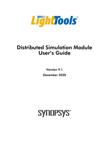
Optical Design Toolsfor Backlight DisplaysIntroductionBacklights are used for compact,portable, electronic devices with flatpanel Liquid Crystal Displays(LCDs) that require illuminationfrom behind. Applications includedevices as small as cell phones andas large as big-screen TVs. Goalsfor backlight design include lowpower consumption, large area withsmall thickness, high brightness,uniform luminance, and controlledviewing angle, either wide or narrow. To achieve these challengingdesign goals with a cost effectiveand timely solution, it is necessary touse computer-aided optical designtools to expedite the design. Thispaper describes features in ORA’sLightTools illumination design andanalysis software that enable thedevelopment of state-of-the-artbacklight designs.Optical Design andAnalysis Tools forBacklightsIllumination or lighting systems takelight from one or more sources andtransform it in some way to producea desired light distribution over anarea or solid angle. Illuminationdesign software must be able tomodel the geometric and opticalproperties of different types of lightsources and transforming elements,and it must also be able to evaluatethe paths of light using optical raytracing through the model to calculate the final light distribution.The light distributions are calculatedusing Monte Carlo simulations tocalculate illuminance, luminance, orluminous intensity over the desiredareas and/or angles. Rays are startedfrom random locations and directions from the source(s), tracedthrough the optical system, and collected on receivers. Illuminance canbe calculated for rays collected onsurface receivers and intensity forrays collected on far field receivers.By defining a luminance meter forsurface receivers, the spatial orangular variation of luminance canbe calculated from that surface.In some cases, it may be importantto analyze the chromaticity of a display. The spectral energy distribution of the sources (such as LEDs)can be specified. The output of CIEcoordinates, together with correlated color temperature (CCT),quantifies the colorimetric behaviorof the display. An RGB photorealistic rendering of the display outputcan also be generated. All of theseanalyses are available in LightTools.Aspects of backlight displays makeparticular demands on illuminationanalysis software. As will be discussed, the means by which light isextracted from a backlight relies oneither dense patterns of paint dots orpatterned microstructures. Modeling microstructure arrays in particular can result in extremely largemodel sizes if created explicitly as aCAD model. LightTools providesthe capability to define arrays of 3Dtextures that ray trace and renderaccurately but are not explicitly1constructed as part of the geometricmodel, thereby resulting in muchsmaller model sizes and much fasterray tracing.A second aspect of backlight analysis involves ray splitting and scattering from the surfaces of the lightguide. Because Monte Carlo simulations are used to analyze the illumination performance, a potentiallylarge number of rays must be tracedto get sufficient accuracy for comparison of designs. It is most effective to trace rays that carry most ofthe flux. This can be achieved byusing probabilistic ray splitting totrace the paths with the most flux,and allowing use of aim areas orsolid angles for scattering surfaces todirect scattered light in “important”directions (i.e., toward the displayobserver).What is a Backlight?A typical backlight consists of alight source, such as a Cold CathodeFluorescent (CCFL) or Light Emitting Diodes (LEDs), and a rectangular light guide, which is also referredto as a light pipe. Other elementsthan can be used include a diffuser,which enhances display uniformity,and a brightness enhancement film(BEF), which enhances displaybrightness.The light source is usually located atone edge of the light guide to minimize the thickness of the display.Edge lighting typically uses totalinternal reflection (TIR) to propagate light along the length of the
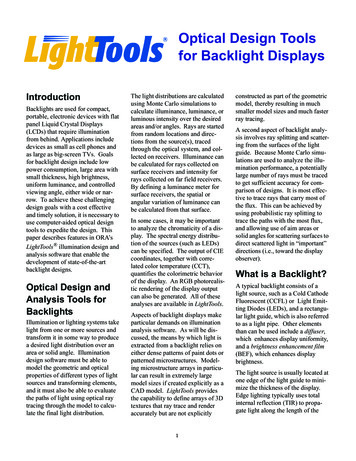
ReflectorAs shown in Figure 3, the availablepower is highest at the source end ofthe light guide and falls off withincreasing distance from the source.To obtain uniform output, the extraction efficiency must increase withdistance from the light source.Developing a light guide that exhibits the necessary variation in extraction efficiency is one of the primarytasks in designing a backlight.(BEF)DiffuserLight GuideTwo extraction techniques can beused. The printed light extractiontechnique uses patterns of paint dotson the bottom of the light guide toLight SourceFigure 1. Schematic of a Typical Backlightdisplay. Figure 1 shows a schematicof a typical backlight design.The backlight designer has severaloptions for modeling light sources inLightTools. CCFL sources of different shapes (e.g., straight, L-shaped,U-shaped, or W-shaped, shown inFigure 2) can be rapidly definedusing the Fluorescent Lamp CreationUtility. Reflectors for the lamp canbe defined using a variety of LightTools geometric primitives, such ascylinders, elliptical troughs, andextruded polygons; reflectorsdefined in CAD systems may also beimported via standard data exchangeformats (IGES, STEP, SAT andCATIA).If LEDs are used, the designer canchoose the desired LED model frompre-stored catalogs of models fromFigure 2. Fluorescent Lamp Building BlocksAgilent, LumiLeds, Nichia, orOsram.Once the light is directed into theside of the light guide, the problembecomes extracting the light out ofthe light guide perpendicular to thedirection of propagation.scatter light upward and out of thetop of the light guide. The secondtechnique, molded light extraction,relies on TIR from microstructuresor textures patterned on the bottomsurface to redirect light out of the topof the light guide.LightTools supports the design oflight guides via the BacklightDesign Utility. This tool (Figure 4) assists the user in creatExtraction efficiencying the different parts of abacklight. There are optionsfor adding source/reflectorUniform outputcomponents to the model, BEFmodeling, and setting up areceiver for illumination analysis. The main focus of theBacklight Utility is multipletabs for setting up andAvailable powerDistance from the sourceFigure 3. Requirements for Light Extraction from Light Guides2
Bezier curve. The LightTools 2DZone Utility is used to set up nonlinear patterns.Figure 5 shows an example usingpainted light extraction in whichthree parameters (paint dot width,height, and vertical spacing) are varied to create variable extractionbehavior.The output uniformity is shown inFigure 6. The slice on the rightshows that the average output luminance is constant.Figure 4. LightTools Backlight Design Utilitymodifying extraction mechanisms ofdifferent types.For backlights using the printed lightextraction method, the BacklightUtility provides options for linearvariation in paint dot size and aspectratio, as well as linear variation ofdot spacing along the length of thelight guide. This type of patternvariation will often give a goodstarting point for a uniform display,but is not sufficient to meet the finaluniformity requirements. Additionalcontrol of output uniformity can beobtained by allowing non-linearvariation of extraction parameters.An approach that gives very flexiblecontrol with a minimum of parameters is to define the variation of aparameter in terms of a quadraticThe second extraction method,molded light extraction, uses the 3Dtexture capability in LightTools. The3D texture feature is designed to raytrace repetitive structures very efficiently and store the informationvery compactly. Models createdusing explicit geometry can tracemore than 30 times slower and havemodel files more than 100 timeslarger than equivalent models created using 3D textures. Three different basic shapes are available:spheres, prisms, and pyramids(Figure 7).The Backlight Utility provides ameans for setting up linearly varyingpatterns of the microstructure types.Bezier with Control Net2.521.510.50051015Zone Number2025Figure 5. Variable Light Extraction Using Quadratic Bezier Curves3
4-0.2-0.00.20.400.0X0.10.20.30.4Figure 6. Output Uniformity of Backlight Using Paint DotsThe 3D Texture Utility can be usedto vary the texture parameters nonlinearly using a quadratic Beziercurve. An example where a groovemicrostructure (modeled using theprism 3D texture) is used as anextraction mechanism is shown inFigure 8.The resulting light guide and its performance is shown in Figure 9.Optical Calculationsfor BacklightsTwo of the most important opticalquantities for backlight displays aredisplay luminance and illuminanceuniformity on the top of the lightguide. Calculation of luminousintensity and various colorimetricquantities (CIE coordinates andCCTs) are important as well.LightTools has built-in support forthese calculations and a number offeatures to aid in understanding theresults of the Monte Carlo simulations used to generate the data.Monte Carlo simulations are thefoundations of the illumination calculations in LightTools. It is generally understood that random numbergenerators are used to pick startingray positions, directions, and wavelengths to sample the light distributions on the receivers. Theconvergence of the simulations canbe dramatically affected by how the“random” numbers are chosen.Using low discrepancy (Sobol) number sequences, which are not randomat all, can improve the reduction oferror from 1 N to 1/N, where Nis the number of rays at the receiver.A comparison of colorimetric resultsusing random number sequences(Figure 10) and Sobol numbersequences (Figure 11) is shown onpage 6. For this case, it would take128,000 rays using a random number generator to equal the accuracyof a 16,000-ray Sobol sequence simulation. It is important to recognizethe simulation convergence speedwhen comparing different software,since it is the speed with which youget to a certain accuracy level, notthe speed it takes to trace a certainnumber of rays, that is important.Receivers in LightTools collect raydata for illumination calculations.Figure 7. Sphere, Prism and Pyramid 3D Textures4
Bezier with Control Net0.350.30.25X0.20.150.10.050010203040Zone NumberFigure 8. Definition of a Groove MicrostructureThe ray data is collected on datameshes for analysis and display.The user can interactively controlthe dimensions or number of bins inthe data meshes. For a given number of rays on the receiver, mesheswith a small number of bins willhave low spatial or angular resolution but high relative accuracy (lowerror), while meshes with a largenumber of bins will have better resolution but lower accuracy (greatererror). An error estimate can be displayed for each bin in a mesh to helpthe user decide if enough rays havebeen traced in the simulation to meetthe resolution and accuracy neces-sary to assess the design(Cassarly, W.J., Fest, E.C., andJenkins, D.G., 2002). If more raysare needed, the user may interactively continue the simulation untilthe goals are met.split rays result, most of which carrylittle energy, thereby slowing theanalysis. An example of this isshown in Figure 12, which showsthe many paths of a single startingray due to beam splitting.An important aspect of backlightanalysis involves ray splitting andscattering from the surfaces of thelight guide. The nature of the lightguide is that a ray can bounce aroundthe inside of the light guide numerous times prior to becomingabsorbed or exiting the guide. If aray is split into a transmitted andreflected part for each surface interaction, an extremely large number ofA simulation was run where 2000rays were started from the sourceand, due to ray splitting, 277,948rays were collected on the receiver(Figure 13). Because most of therays reaching the receiver had littleenergy, the error for the result was42%.If, instead, one traces the ray probabilistically, with the probability of .4-0.2-0.0X0.20.400Figure 9. Light Guide Performance with Groove Microstructure5100200300400
tering surfaces to allow the user toindicate where the scattered ray samples should be directed. This is aform of importance sampling and isanother method for improving theconvergence of a Monte Carlosimulation.Figure 15 shows a luminance meterand a backlight with a diffuser without an aim cone. Two thousand rayswere traced from the source, and theluminance meter collected 40 rays,as shown by the raster plot of spatialluminance.Random: 16,000 raysFigure 10. Colorimetric Calculations using Random Numberray transmitting or reflecting determined by the Fresnel loss coefficients or scattering properties at thesurface, the bulk of the ray tracingtime will be spent following the flowof the energy in the system, therebyspeeding analysis. The results of asimulation where 200,000 rays werestarted from the source are shown inFigure 14. In this case 118,969 raysreached the receiver with an errorestimate of 6% for the calculation.The probabilistic ray trace modereduced the error in the calculationby 7x and, at the same time, reducedthe calculation time by 42%.Finally, diffusers are sometimes usedabove the top surface of the lightguide to improve the angular uniformity of the display. Because diffusers spread rays over a wide angle,few rays would be scattered into theluminance meter aperture, and cal-The value of importance samplingcan be seen in Figure 16, whichSobol: 16,000 raysFigure 11. Colorimetric Calculations using Sobol Sequenceculating the luminance normal to thedisplay as measured by a typicalluminance meter would require anextremely large number of rays.LightTools provides for aim areas oraim cones to be associated with scat-Figure 12. Light Guide Traced with Ray Splitting6shows the same case but with an aimcone added to the diffuser. The aimcone is matched to the acceptanceangle of the luminance meter aperture. When a ray is incident on thediffuser, LightTools will generate thescattered ray (with the flux into theaim area determined appropriatelybased on the full angular distributionof the diffuser model) into the aimcone, so that the luminance metercollects all of the scattered rays,thereby improving the convergenceof the simulation. In this case, of the2000 rays started, 1416 rays (71%)were collected by the luminancemeter.
which the user can enable whenneeded, tracks the polarization stateof the ray as it propagates using aStokes vector.Figure 13. Results of Ray Splitting SimulationAdditionalConsiderationsBacklights are widely used with Liquid Crystal Displays (LCDs), whichare polarizing components. Thecapability to model polarizing components such as linear polarizers andquarter wave plates and evaluatetheir effects via polarization ray tracing can be critical to the success ofan analysis. LightTools providessimple linear polarizer and retardermodels, as well as specification ofpolarization components by theirJones or Mueller matrices. Thepolarization ray tracing feature,It is often necessary to treat components with optical coating with various transmission, reflectance, andpolarization properties. Coatings aredefined in LightTools in terms oftheir performance, which is often theonly information available to theuser. The average or the individualS or P values of reflectance andtransmittance can be specified inFigure 14. Results of Probabilistic Ray Traceterms of any two of the followingparameters: angle of incidence,wavelength, X position, or Y position. A utility to convert coatingstack definitions into the LightToolsperformance coating format is alsoavailable.While most backlights use printed ormolded extraction techniques, otherapproaches are possible. One is touse scattering from particles in thelight guide itself. If the particle sizesand density are controlled appropriately, Mie scattering from the particles can efficiently extract light fromthe light guide (Tagaya, et al.,2001:6274). LightTools can simulate volume scattering according tothe Mie theory for spherical particlesFigure 15. Spatial Luminance for Diffuser without Aim Cone7
opment of illumination design software with features specificallyintended to reduce the design cycletime for new backlight development.Key features in LightTools addressing model creation and size, raytrace and simulation time, and calculation of a wide range of opticalparameters relevant to the design ofbacklights have been identified anddemonstrated.Figure 16. Spatial Luminance for Diffuser with Aim Coneor according to a user defined angular distribution.Exporting completed optical designsto CAD systems is often a necessarystep toward manufacturing the lightguide. Support of standardexchange formats such as STEP,SAT, or IGES is needed to accomplish this. In the case of moldedextraction designs, this also requiresthat the 3D texture definitions of themolded features be translated intoexplicit geometry for the dataexport, because data exchange stan-dards support the transfer of explicitgeometry only. LightTools supportsthe standard formats and can optionally export files with 3D texturesconverted to explicit geometry sothat the entire backlight is represented in the exchange file.SummaryThe field of backlight design continues to evolve rapidly in response tomarket demand for better performance and reduced costs. Thisevolution is supported by the devel-LightTools includes noise-tolerantillumination optimization, which isvery useful for backlight designers.This capability allows light extraction patterns, which maximizepower and uniformity, to be determined automatically. In addition, theLightTools Backlight Pattern Optimization utility provides an efficientway to optimize the output distribution specifically for backlights andlight pipes.ReferencesCassarly, W. J., E. C. Fest, D. G. Jenkins, “Error estimation and smoothing of 2D illumination andchromaticity distributions,” SPIEProc., Vol. 4769, 2002.Tagaya, A., M. Nagai, Y. Koike, K.Yokoyama, “Thin Liquid-CrystalDisplay Backlight System withHighly Scattering Optical Transmission Polymers,” Applied Optics-OT,Vol. 40, Dec. 2001.3280 East Foothill Boulevard, Pasadena, California 91107Telephone: (626) 795-9101 FAX: (626) 795-0184E-mail: service@opticalres.com Web site: http://www.opticalres.com8
lar light guide, whic h is also referred to as a light pipe. Other elements than can be used include a diffuser, which enhances display uniformity, and a brightness enhancement film (BEF), which enhances display brightness. The light source is usually located at one edge of the light guide to mini-mize the thickness of the display.