Transcription
Hydraulic-Powered Stationary CompactorsInstallation, Operation& Service ManualHEAVY DUTYINDUSTRIALINDUSTRIALCOMMERCIALHeavy DutyIndustrial -331CP-711CP-1501CP-2101CP-3101CP-4101Built with Pride
Hydraulic-Powered Stationary CompactorsStop! Read the Following Safety Information Before Operating the EquipmentSP Industries, Inc., has made every reasonable effort to produce a product that willperform successfully and safely during its expected life span for the owners andpersons operating the equipment. To increase the safety while operating this unit, allpersons should closely follow these safety tips, as well as the safety guidelines in theANSI Z245.2 Safety Standards for Stationary Compactors booklet included with thecompactor and all OSHA guidelines.1.As per OSHA standards, install safety rails and guards on walk ways, decks, andhopper openings. Check your local OSHA regulations for additional requirements.2.Erect suitable barriers around cart dumpers, conveyors, etc. to keep personnelclear of hazardous areas during operation.3.Make sure all access covers are in place before starting the machine.4.Keep the compactor working area clean, uncluttered, free of ice and snow, andespecially free of oil and grease.5.Locate the remote control head so the operator can clearly see the chargingchamber, although the controls should not be mounted where the operator hasaccess to the charging chamber.6.Inspect the container binders and make sure they are securely fastened to thecontainer as well as to the compactor.7.Secure the container door safety chain before attempting to elevate or transportthe container.8.Securely lock the container to the hoist frame before transporting.9.DO NOT drop solid objects such as steel plate, steel bar, castings, concrete,etc. into the chamber, this type of material will seriously damage the compactorcompaction chamber and/or container; and will void warranty.10.DO NOT stand near the compactor when the ram is in motion; material may beejected from the charging chamber and cause serious injury.2www.bestcompactors.com Phone: 800.592.5959 Email: info@sp-industries.com
Installation, Operation & Service ManualProcedures for Electrical Arc Flash and Shock SafetyReferences:OSHA 29 CFR 1910 Subpart S; - OSHA 29 CFR 1926 Subpart K; NFPA 70 E-2012WARNING: ARC FLASH, BLAST, AND SHOCK HAZARDUSE PROPER ELECTRICAL SAFE WORK PRACTICESInstaller and Operator Precautions1.Prior to intentionally coming into contact with energized electrical conductorsor circuit parts of 50 volts or greater with the hands, feet, or other body parts,with tools, probes (energized electrical work) a shock & hazard analysis shall beperformed to determine the safe work practices required to perform that work (perthe requirements of NFPA 70E - 2012).2Those safe work practices shall include at a minimum the identification of:a.Electrical shock and arc flash boundaries.b.Personal protective equipment to be worn.c.Need for electrically insulated measuring equipment & other tools.3.Energized electrical work shall only be performed by/under supervision of aQualified Person, as defined by OSHA & NFPA.4.Qualified Persons shall be trained as defined by OSHA and NFPA.5.All other workers performing energized electrical work shall be trained at aminimum to:a.Understand the specific hazards associated with electrical energy.b.Understanding the safety-related work practices and proceduralrequirements necessary to provide protection from the electrical hazardsassociated with their respective job or task assignments.c.Identify and understand the relationship between electrical hazards andpossible injury.d.Other specialized work practices to be followed to perform work safely.e.Requirements for the use of an Electrical Hot Work Permit3www.bestcompactors.com Phone: 800.592.5959 Email: info@sp-industries.com
Hydraulic-Powered Stationary CompactorsTable of ContentsSafetyInformation23Safety PrecautionsProcedures for Electrical Arc Flash and Shock SafetyInstaller and Operator PrecautionsCompactorSafety Rules5Remote Control HeadFunnels, Hoppers, Chutes and Security ChutesLoading RefuseTools Requiredfor Installation5Power LockoutProcedure6Installation78Lifting the Compactor ProperlyLeveling the CompactorAnchoring the CompactorHydraulic ConnectionsHydraulic FluidElectrical Connections9Initial CyclingContainer and Compactor AlignmentSafety Interlock for Security DoorsPhoto Electric & Infrared Eye SystemsDumpersOperation —Primary1011Automatic Mode OperationManual or Sustained Manual Pressure Mode OperationMachine JammingJogging MachineOperation —Options12Pinning/Boost Override SystemImmersion Oil HeaterAdvance Warning LightHydraulic Cart & Container DumperLow/Hot Oil Warning SystemMaintenance14Compactor Clean OutStrainer CleaningInitial Maintenance CheckHydraulic Fluid ChangesCold Weather 7MotorPumpDirectional Control ValveRelief ValveHydraulic HosesLimit SwitchRam Guide Blocks13Programmable CyclingPhoto Electric, Infrared & Ultrasonic StartRemote Jog ControlAdditional Remote Control Station18Cylinder Piston SealsRelaysTimersStartersMotor OverloadsTransformersTerminal StripSwitchesMotor Fails To StartMotor Starts But Ram Fails To Move4www.bestcompactors.com Phone: 800.592.5959 Email: info@sp-industries.com
Installation, Operation & Service ManualCompactor Safety RulesRemote Control HeadThe remote control head is supplied with a Keyed Off/On Switch, Start Button and aStop Button. This remote control head must be permanently mounted within three feetof the point of operation.FunnelsHoppersChutesSecurity ChutesAll Access doors and/or safety gates on factory built funnels, hoppers, chutes andsecurity chutes are provided with factory installed interlock switches where required. Ifthe funnel, hopper, etc. is installed at the job site, it is the responsibility of the installerto provide an interlock system so that the compactor may only run when all safetygates and access doors are closed.All factory built equipment is safety marked with applicable safety labels required bycurrent ANSI Z245.2 Safety Standards. It is the responsibility of the owner to obtainthese labels and apply them to all chutes, hoppers and funnels built by anyone at thesite of the compactor or built elsewhere and brought to the site for installation.All funnels, hoppers, chutes and security chutes should be mounted to the compactorwith low hydrogen rod welds; smaller units may be bolted securely to the compactor.Loading Refuse1.DO NOT enter the charging chamber.2.DO NOT throw solid objects such as steel plate, castings, concrete blocks, etc.into the chamber, this type of material may seriously damage the compactorand/or container. Note: This will Void The Warranty.3.DO NOT operate dumping devices unless area is clear of all personnel. OSHAand the manufacturer require erection of suitable barriers when these devicesare used.4.DO NOT stand near the compactor when the ram is in motion; material may beejected from the charging chamber and cause serious injury.To avoid falling into the compaction chamber, stay at a safe distance when loadingrefuse into the compactor. After the refuse has been loaded into the chamber, stand ata safe distance during operation.Tools Required For Compactor Installation1.Fork Lift Truck - To unload and position the machine.2.Hilti Type Drill - For drilling holes in concrete to mount concrete anchors throughthe compactor mounting feet.3.Hand Tools - Various electrical and mechanical tools for connecting hydraulichoses and electrical wiring.4.Welder - For welding machine to cement embedded steel anchor pads ifapplicable or attaching loading hoppers, enclosures, etc.5.Cutting Torch - To adjust or alter optional knock down chute if needed.5www.bestcompactors.com Phone: 800.592.5959 Email: info@sp-industries.com
Hydraulic-Powered Stationary CompactorsPower Lockout ProcedureThe following are the General Industry Safety Division’s minimum requirements forestablishment of a Power Lockout Procedure.A written power lockout procedure shall be provided.All necessary employees shall be instructed on this procedure. Employees shall beinstructed in and conform to the following procedures:1.Alert the operator(s) that power is being disconnected.2.Before starting repair, service or setup work on engine, motor or power drivenequipment, person(s) performing work shall make sure power is disconnected(and any hazardous residual pressure shall be relieved) prior to and during suchwork. A padlock(s) shall be placed at the point of power disconnect where lockoutis required by each person(s) performing work. Individual locks shall be used oran authorized employee of each crew shall be responsible for placing the lockand determining that each crew member is clear before removing the lock, or asupervisor may place a lock for which he has the only key, and assure that allcrews are clear before removing the lock. Keys shall be removed at the time oflockout. Before work is started, equipment shall be tested to insure power is off.3.No one other than person(s) placing padlock(s) on power lockout shall removepadlock(s) and restore power. (Exception: Supervisor may remove padlock(s) andrestore power after a thorough check to make sure that no person will be exposedto danger.)4.If it is necessary to work on a machine or installation to be continued by the nextshift personnel, the padlock(s) of the original employees shall be removed bythose employees in the presence of the oncoming shift who will immediately inserttheir own padlock(s) into the disconnect. All concerned personnel (operators,repairmen, and supervision) shall be thoroughly informed.5.A machine connected to an electrical source by a plug-in cord shall be consideredin compliance if the plug is disconnected and tagged, provided that the plug is alegal disconnecting means. (Plugs are acceptable as disconnecting means only forportable motors and 100V fixed equipment.)6.Any equipment component that needs blocking to prevent its movement by gravityor other means must be blocked.6www.bestcompactors.com Phone: 800.592.5959 Email: info@sp-industries.com
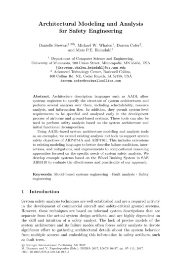
Installation, Operation & Service ManualInstallation InstructionsLifting theCompactor ProperlyThe compactor can be off-loaded or moved from either the side or small compactorscan be lifted from the chamber end by securing it to the fork lift truck with a chainaround the breaker bar:Lifting compactor from the chamber endLifting a compactor from the sideThe fork lift must be large enough to handle the weight of the compactor. If the fork liftwill not lift the unit or if the unit is unbalanced when lifted, the compactor must be liftedwith a larger fork lift or two fork lifts on opposite sides. To balance the compactor whenlifting from the side the forks must be positioned off center, closer to the chamber end,to compensate for the greater weight at this end.Once the compactor is in its approximate position, its position can be adjusted withoutlifting it completely off the concrete. Lift one end of the compactor and shift it intoposition with the fork lift.Leveling TheCompactorAnchoring TheCompactor1.Set the compactor on the concrete pad.2.Place a jack under the front of the compaction floor or floor support. Be sure thatthe jack is in the center of the floor using a tape measure as shown.3.Raise the compactor until both front legs are off the ground.4.If both legs leave the floor at the same time, the concrete is level. Lower thecompactor and proceed to anchor the compactor to the concrete.5.If one leg is higher than the other, the concrete is not level. Lower the compactoruntil one leg touches the concrete, then shim the leg which is still raised.6.Once the leg is shimmed, anchor the compactor to the concrete.If the installation drawing guide lines are followed, enough clearance will be allowed forservicing internal parts through the rear or optional side access panels. Some units areequipped with top access panels only.The compactor must be bolted securely to a concrete slab and located as illustrated onthe installation drawing. SP Industries recommends using anchorable mounting padsembedded in the concrete if new concrete is poured or anchors such as ThunderboltConcrete Anchors if existing concrete is used. The installation drawing shows themounting hole pattern and anchor pad layout.CAUTION: If the concrete is not level, all four compactor mounting pads will not betouching the cement. If this is the case, do not pull the legs to the concrete, the legswhich do not touch must be shimmed then fastened securely. If the raised leg is pulleddown, the frame could be twisted causing a gap between the ram and floor surface,resulting in undue jamming and premature floor wear.7www.bestcompactors.com Phone: 800.592.5959 Email: info@sp-industries.com
Hydraulic-Powered Stationary CompactorsInstallation Instructions (cont.)HydraulicConnectionsThe hydraulic connections may have loosened during shipment; therefore, they shouldbe checked for tightness. When connecting the hoses from the power unit to thecylinder(s), apply thread sealant around or apply liquid pipe sealant to all male threadsthat do not connect to a factory supplied swivel fitting.CAUTION: When using liquid pipe sealant, do not allow sealant to seep into the pumpor valve; severe damage may result.Hydraulic lines over and above standard hose length, usually ten feet, require schedule80 pipe and 3,000 lb. pipe fittings. If the lines are more than 20 feet long, pipe with alarger diameter must be used to prevent pressure losses. Vibration can be lessened byusing hydraulic hose between the cylinder connection and the pipe line, and betweenthe pipe line and the power unit.During operation, hydraulic hoses should not rub against an abrasive surface. Whenthe ram changes direction, the pressure change will cause the hoses to move. Rubbingcould cause leakage, usually starting in the form of a mist and eventually turning intoa steady stream. An explosion could occur if an open flame came in contact with theleaking oil.Hydraulic FluidThe reservoir must be filled with a premium grade hydraulic fluid having a viscosityindex of approximately 100, and a viscosity of 32 CST @ 40o C or an ISO VG32.Thermostatically controlled immersion oil heaters are recommended for extremeconditions. Also, the fluid must have anti-foam, anti-wear and water separatingadditives. Acceptable hydraulic fluids for all other conditions are as follows::ShellT S2M32Gulf Harmony 32Exxon Nuto H32ElectricalConnectionsShevron Rando HD 32Mobile D.T.E. 24CAUTION: The electrical controls must be connected to the correct power source(208, 230, 460, etc.).Power to the unit must be provided through a customer furnished fusible disconnectswitch which is visible and accessible to the operator of the unit. Local electrical codesshould be consulted for proper installation specifications.The voltage that the unit is factory wired for is listed on the decal attached to the mainelectrical box door.If the incoming line voltage differs from the power unit factory wired voltage, the motorconnections, transformer connections, motor starter overloads, and the size of powerline wires, if they are not rated for higher line current, must be changed. The wiringdiagram will show the correct wire and overload size. In some cases on motors over 10HP, the motor and starter may also have to be changed.8www.bestcompactors.com Phone: 800.592.5959 Email: info@sp-industries.com
Installation, Operation & Service ManualInstallation Instructions (cont.)Initial CyclingBefore the unit is coupled to the container, it should be cycled several times. Duringthis cycling, observe all pipe and hose connections for leakage.If the pump makes loud or crackling noises and/or the ram jerks, stop the machineand tighten all intake connections to the pump from the tank. After smooth cycling isobserved, stop the ram in the RETRACTED POSITION and check the fluid level on thesight gauge. If the sight gauge indicates that the reservoir is not full, add an acceptabletype of hydraulic fluid until the gauge indicates that the reservoir is full. Full is at a pointbetween the top of the thermometer and the black line.Container andCompactorAlignmentOne inch all-around clearance should be observed when the container is connected tothe compactor charge opening. The compactor mating surface of the container shouldfit flush with the mating surface of the compactor.If a gap is present on the top or bottom, the front or rear legs of the compactor and/orthe wheels of the container, must be shimmed until proper alignment is reached. Donot over tighten the container hooks. The container should only be drawn snug againstthe compactor.Hopper Door,Security Chute orSafety GateInterlock SwitchIf the compactor is equipped with a hopper, security chute or safety gate which uses asafety interlock switch, the gate or door must be closed to operate the compactor. Withthe interlock switch in a closed position, power will pass to the control system allowingthe machine to operate.Adjustable decks and deck extensions must be installed so they are level. The centersupport arms of the deck must be welded to the compactor side frame.Safety handrails must be installed on all decks as per OSHA standards.Photo Electric& Infrared EyeSystemsIf the compactor is equipped with a photo electric eye or infrared eye, the reflector orreceiver must be properly mounted opposite the eye to reflect the light beam, also thelight beam must be free of obstructions.Safety for DumpersIt is the owner’s responsibility to provide suitable safety enclosures and/or gates for alldumpers.Safety interlock switches enabling the dumper to be operated only when gates areclosed must be mounted on all gates leading to the dumping area. SP Industries, Inc.,can provide safety decals to post on or near safety enclosures and gates constructedon the job site.The dumper controls, except when remote controls are ordered, are mounted in themain control panel or on the remote control head with the compactor controls. Thecontrols consist of a Keyed off-on Switch, Start Button, Stop Button, Motor runningLight, and an Up/Down Selector Switch. Pushing either the Dumper Stop Button or theCompactor Stop Button will stop the dumper in any position. When the dumper runninglight is “on”, this indicates that the dumper motor is running.9www.bestcompactors.com Phone: 800.592.5959 Email: info@sp-industries.com
Hydraulic-Powered Stationary CompactorsCompactor Operation — PrimaryAutomatic ModeOperationCAUTION: The Power supply to the controls MUST BE TURNED OFF whileadjustments in the control panel are made.1.Set 1 TGS (Auto/Manual Toggle Switch) in the “auto” position.2.Set 2 TGS (Stop/Extend or Stop/Retract Toggle Switch) to the desired ram stopposition at the end of the timed cycle.3.Set 1 TR (Five Minute Cycle Timer) as desired. The machine can be set to cyclefrom one complete cycle to indefinite cycling time. 2 TR (One Minute ContainerFull Timer) has been preset and marked at the factory. Do not tamper with thistimer. If 2 TR is set wrong, the unit will not function properly. The proper setting is8 seconds above the forward stroke time.4.2 SS (Retract/Run/Extend Selector Switch) is spring loaded to center in the“run” position. It is only used in the other positions for jogging (an option oncommercial models).5.1 SS (Jog/Run Selector Switch) should be set in the “run” position. 1 SS shouldonly be switched when manually jogging the ram back and forth. Usually it isonly used by the container hauler. (This is an option on commercial models.)6.3 SS (On/Off Selector Switch) should be set in the “on” position.7.After steps 1-6 are completed, the electrical disconnect may be switched to the“on” position.8.PUSH THE START BUTTON: In the automatic mode, the machine will continueto run until:a.1 TR has timed out, stopping the ram in the desired position.b.The ram is unable to reach the limit switch because of a full load or anobstruction. This will be indicated when the full container light, located inthe Stop Button, lights. Before the automatic mode will continue, the StopButton must be pushed to reset 2 TR.c.The Stop Button is pushed to the “stop” position.10www.bestcompactors.com Phone: 800.592.5959 Email: info@sp-industries.com
Installation, Operation & Service ManualCompactor Operation — Primary (cont.)Manual or SustainedManual PressureMode OperationCAUTION: The Power supply to the controls MUST BE TURNED OFF whileadjustments in the control panel are made.1.Set TGS (Auto/Manual Toggle Switch) in the “manual” position.2.Set 2 TGS (Stop/Extend or Stop/Retract Toggle Switch) to the desired ram stopposition at the end of the timed cycle3.2 SS (Retract/Run/Extend Selector Switch) is spring loaded to center in the “run”position. (This is an option on some models.)Machine Jamming4.1 SS (Jog/Run Selector Switch) should be set in the “run” position. 1 SS shouldonly be switched when manually jogging the ram back and forth. (This is an optionon some models.)5.3 SS (On/Off Selector Switch) should be set in the “on” position.6.After steps 1-5 are completed, the electrical disconnect may be switched to the“on” position.7.PUSH AND HOLD THE START BUTTON,, the machine will continue to run until:a.The Start Button is released.b.The ram is unable to reach the limit switch because of a full load or anobstruction. This will be indicated when the full container light, located inthe Stop Button, lights. Before the automatic mode will continue, the StopButton must be pushed to reset 2 TRIf the forward movement of the ram is impeded, the full/jam indicator, located inside theStop Button, will light.This indicates that either the container is full or an object such as an oversized skidor a 4 x 4 is wedged in the charging chamber. If the unit is jammed but the containeris not full and the compactor is equipped with jog controls, operate the jog controls asdescribed below. If the machine is not jammed but the container is full, the containermust be emptied.If the ram jams on the reverse stroke, there is probably an object wedged between theram floor and compactor floor or refuse buildup, possibly caused from an improperlyworking top scraper, jamming the ram from the back. In any case, the jamming objecthas to be freed before the automatic cycling can continue.CAUTION: All power must be turned off and locked out before entering the machine toremove the object causing the jam.Machine JoggingNOTE: Jog controls are an option on commercial compactor models.1.Set 1 SS (Jog/Run Selector Switch) in the “Jog” position.2.Hold 2 SS (Retract/Run/Extend Selector Switch) in either the “extend” position forforward ram movement, or “retract” for rearward ram movement.11www.bestcompactors.com Phone: 800.592.5959 Email: info@sp-industries.com
Hydraulic-Powered Stationary CompactorsCompactor Operation — OptionsPinning/BoostOverride SystemNOTE: The Pinning/Boost Override System is standard on the CP-6002, CP-6002-D,CP-7002, CP-7002-D, CP-8002, be CP-13001, and all precrusher/compactors. It is anoption, when available, on all other compactor models.This system adds 300 PSI (Approximately 9,000 lbs. force per 6” cylinder) boostpressure over the regular operation pressure of the machine. The system includesright or left side machine mounted boost controls, a dual solenoid spring centereddirectional valve, and a pressure actuated switch.The pinning/boost override system operates similar to the jogging mode of operation.1.Set 1 SS (Pin/Off/Run Selector Switch) to the “pin” position and hold (this switchwill return to the “off” position when released).2.Hold 2 SS (Ram Extend/Retract Selector Switch) in either the “extend” positionfor forward ram movement, or “retract” position for rearward ram movement.This system overrides the auto or sustained pressure operation of the unit and deliversan extra 300 PSI to the cylinder. The boost pressure has been preset at the factory;any unauthorized adjustments of this pressure will void the warranty.Immersion Oil HeaterThe heater is adapted to the one inch NPT half coupling at the end of the tank underthe electrical box and necessitates the use of a larger transformer.The heater is thermostatically controlled to maintain oil temperature at the desiredsetting during cold weather. The heater will maintain the temperature only while thedisconnect supplying power to the electrical box is in the “on” position.Advance WarningLightThe advance warning light consists of a pressure regulated switch, an additional relayand a warning light which is mounted with the other controls.The purpose of this system is to alert the operator when a pressure less than themaximum operating pressure is reached. The pressure is factory set at approximately80% of normal operating pressure. This will allow the advance warning light to indicatewhen the container is approximately 80% full; giving the operator time to contact thehauler to change containers for minimal compactor down time.Hydraulic Cart &Container DumperA hydraulic dumper consists of a side, deck, or remote mounted dumping mechanism;and a separate motor, valve, pump and operating controls.A typical dumper will have its hydraulic components mounted on the same reservoir asthe compactor’s hydraulic components and the operating controls in the same controlpanel as the compactor’s operating controls. The dumper may be started with orwithout operating the compactor as long as 2 SS is in the “Run” position, 1 SS is in the“On” position and the compactor stop button is in the closed (up) position.Low/Hot OilWarning SystemThe low/hot oil warning system consists of reservoir mounted, low oil and hot oilsensing devices, a warning light, and an additional relayThe low sensing devices send a signal to the warning light, mounted with the othercontrols, and shuts the motor/pump off when the oil level is dangerously low or hot.When the light comes on, the reservoir hydraulic fluid must be checked and filled to theproper level as read on the oil sight gauge and/or replaced if damaged from excessiveheat. The cause of the low or hot oil condition must be determined and repaired beforethe motor is started again.12www.bestcompactors.com Phone: 800.592.5959 Email: info@sp-industries.com
Installation, Operation & Service ManualCompactor Operation — Options (cont.)ProgrammableCyclingThe programmable cycling system consists of an additional timing device, an additionalrelay, extra starter mounted contacts, and a warning strobe light and buzzer mountedon top of the electrical box.WARNING: When a programmable cycling system is used, special precautions musttaken to make the compaction area off limits to all unauthorized personnel. All safetydevices such as warning lights, etc. must be working properly and all chute and hopperdoors and gates must be closed and locked when not in use for dumping purposes.Once the compactor has been started, it cycles automatically until the stop buttonis pushed or the end of the preset cycle time is reached. 1 TR allows the compactorto cycle for its preset amount of time. 3 TR allows the compactor to maintain an “off”condition for its preset amount of time.To operate the programmable system, set the switches in the following positions:1 TR set for desired “on” time3 TR set for desired “off” time1 SS set to “run” positionTurn the power to the electrical panel on.Push the Start Button.To immediately stop the cycle at any time, push the Stop Button. In order to make thesystem inoperative, remove 3 TR from the electrical box.Photo Electric,Infrared, & UltraSonic Start SystemsThe photo electric, infrared, or ultra-sonic start systems consists of a photo electric,infrared, or ultra-sonic eye assembly, a reflector or receiver, and a warning strobe lightand buzzer.The controls are set the same as the controls for the automatic mode, page 9-10. Thecycle will start automatically after the material in the compaction chamber builds up toa point where it blocks the signal between the eye and the reflector, and the warninglight and buzzer have been activated for 15 seconds.The compactor will continue to cycle until 1 TR reaches its preset cycle time, thecontainer is full or the Stop Button is pushed.Remote Jog ControlNOTE: Jog controls are an option on all commercial compactor units.The jog-run controls are typically mounted on the front of the electrical box; however,if required they can be mounted on the side of the compactor. These controls are usedfor manually jogging the ram as outlined on page 10. The jogging function operates onnormal operating pressures; it does not apply additional pressure like a boost system.Additional RemoteControl StationIf the compactor is to be operated from more than one location, additional remote controlstations are available. All stations will have Keyed Start Switches, Start and Stop Buttons.In order for the machine to operate properly, ALL Keyed Start Switches must be in the “On”position. All stop buttons MUST be wired in series and be in the closed (up or out) position.13www.bestcompactors.com Phone: 800.592.5959 Email: info@sp-industries.com
Hydraulic-Powered Stationary CompactorsMaintenanceCAUTION: Before performing any maintenance on the compactor or power unit, shutoff the power at the disconnect switch and lock this switch in the “Off” position, (seePower Lockout Procedure on page 6). Do not service the machine if it is possible forsomeone to start the machine while it is being serviced.Compactor Clean OutUse the strainer cleaning schedule as a time period to clean out any build-up ofmaterial behind the ram.Strainer CleaningSP Industries Inc. power units use a permanent type oil strain
www.bestcompactors.com Phone 800.592.5959 Email info@sp-industries.com 7 Installation, Operation & Service Manual Installation Instructions Lifting the Compactor Properly The compactor can be off-loaded or moved from either the side or small compactors can be lifted from the chamber end by securing it to the fork lift truck with a chain