Transcription
Axial Piston Fixed PumpA2FORE 91401/06.2012Replaces: 03.081/34Data sheetSeries 6Size510 to 200250 to 1000Open circuitNominal pressure/Maximum pressure315/350 bar400/450 bar350/400 barFeaturesContentsOrdering code for standard program2–– Fixed pump with axial tapered piston rotary group ofbent-axis design, for hydrostatic drives in an open circuitTechnical data4–– For use in mobile and stationary applicationsDimensions size 511–– The flow is proportional to the drive speed and displacementDimensions sizes 10, 12, 1612Dimensions sizes 23, 28, 3214–– The drive shaft bearings are designed for the bearing servicelife requirements usually encountered in these areasDimensions size 4516Dimensions sizes 56, 6318Dimensions sizes 80, 9020Dimensions sizes 107, 12522Dimensions sizes 160, 18024Dimensions size 20026Dimensions size 25027Dimensions size 35528Dimensions size 50029Dimensions size 71030Dimensions size 100031Installation instructions32General instructions34–– High power density–– Small dimensions–– High total efficiency–– Economical design–– One-piece tapered piston with piston rings for sealing
2/34Bosch Rexroth AGA2FO Series 6RE 91401/06.2012Ordering code for standard ic fluidMineral oil and HFD. HFD for sizes 250 to 1000 only in combination with long-life bearings "L" (without code)01 HFB, HFC hydraulic fluidSizes 5 to 200 (without code)Sizes 250 to 1000 (only in combination with long-life bearings "L")E-Axial piston unit02 Bent-axis design, fixed03A2FDrive shaft bearingStandard bearing (without code)5 to 200Long-life bearing250 to 500 710 to 1000–L–Operating mode04 Pump, open circuit05OSizes (NG)Geometric displacement, see table of values on page 7510 12 16 23 28 32 45 56 63 80 90 107 125 160 180 200 250 355 500 710 1000Series606Index0708Directions of rotationViewed on drive shaftNG10 to 1801NG2003NG5 and 250 to 10000clockwiseRcounter-clockwiseLSeals09 FKM (fluor-caoutchouc)Drive shaftsV5–Splined shaftDIN 548010 12 16 23 28 32 45 56 63 80 90 107 125 160 180 200 250 to 1000––––––––10 Parallel keyed shaftDIN ��––––––––––––5 to 2508-holem On request–BP–C355 to 1000–B–– Not availableAZ–Mounting flanges4-holeISO 3019-2 Available1)shaft1)– Preferred programConical shaft with threaded pin and woodruff key (DIN 6888). The torque must be transmitted via the tapered press fit.H
Bosch Rexroth AGA2FO Series 6RE 91401/06.20123/34Ordering code for standard programA2F0102O0304/05606Port plates for service lines2)SAE flange port A/B at side andSAE flange port S at rear12 Threaded port A/B at side and threaded port S at rearSAE flange ports A/B and S at rearThreaded ports A/B and S at side–07V0809105 10 to 16 23 to 250–––––––––111213355 to 1000–05–06–0711Standard / special versionStandard version (without code)13 Standard version with installation variants, e. g. T ports against standard open or closedSpecial version Available2)m On request–Y-S– Not availableFastening thread or threaded ports, metric Preferred program
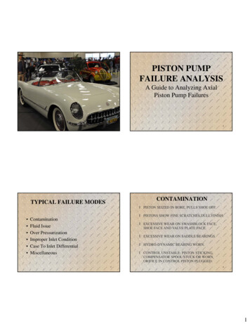
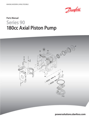
4/34Bosch Rexroth AGA2FO Series 6RE 91401/06.2012Technical dataHydraulic fluidDetails regarding the choice of hydraulic fluidBefore starting project planning, please refer to our datasheets RE 90220 (mineral oil), RE 90221 (environmentallyacceptable hydraulic fluids), RE 90222 (HFD hydraulic fluids)and RE 90223 (HFA, HFB, HFC hydraulic fluids) for detailedinformation regarding the choice of hydraulic fluid and application conditions.The correct choice of hydraulic fluid requires knowledge of theoperating temperature in relation to the ambient temperature:in an open circuit, the reservoir temperature.The fixed pump A2FO is not suitable for operation with HFAhydraulic fluid. If HFB, HFC or HFD or environmentally acceptable hydraulic fluids are used, the limitations regarding technicaldata or other seals must be observed.Selection diagram-40 16001000600400-20 0 60 80 100 1600VG100Viscosity ν [mm2/s]40 010VG 68VG 46VG 32VG 2220020 604036νopt.2016The hydraulic fluid should be chosen so that the operatingviscosity in the operating temperature range is within theoptimum range (νopt see shaded area of the selection diagram).We recommended that the higher viscosity class be selectedin each case.Example: At an ambient temperature of X C, an operating temperature of 60 C is set in the circuit. In the optimum operatingviscosity range (νopt., shaded area), this corresponds to theviscosity classes VG 46 or VG 68; to be selected: VG 68.NoteThe case drain temperature, which is affected by pressure andspeed, can be higher than the reservoir temperature. At nopoint of the component may the temperature be higher than115 C. The temperature difference specified below is to betaken into account when determining the viscosity in the bearing.If the above conditions cannot be maintained due to extremeoperating parameters, we recommend flushing the case atport U (sizes 250 to 1000).105-40 -25 tmin -40 C-10 0 10 30 50 70 90 5115 Temperature t [ C]Hydraulic fluid temperature rangetmax 115 CViscosity and temperature of hydraulic fluidViscosity [mm2/s] TemperatureCommentTmin -50 CTopt 5 C to 20 Cfactory preservation: up to 12 months with standard,up to 24 months with long-termTSt -40 Ct 3 min, without load (p 50 bar),n 1000 rpm (for sizes 5 to 200),n 0.25 nnom (for sizes 250 to 1000)DT 25 Kbetween axial piston unit and hydraulic fluidT -40 C to -25 Cat p 0.7 pnom, n 0.5 nnom and t 15 minTemperature differenceDT approx. 12 Kbetween hydraulic fluid in the bearing and at port T.Maximum temperature115 Cin the bearing103 Cmeasured at port TT -25 C to 90 Cmeasured at port T,no restriction within the permissible dataTmax 103 Cmeasured at port T, t 3 min, p 0.3 pnomT 115 Csee page 5Transport and storageat ambient temperature(Cold) start-up1)nmax 1600Permissible temperature differenceWarm-up phasen 1600 to 400Operating phaseContinuous operationn 400 to 10nopt 36 to 16Short-term operation2)nmin 7FKM shaft seal1)1)2)At temperatures below -25 C, an NBR shaft seal is required (permissible temperature range: -40 C to 90 C).Sizes 250 to 1000, please contact us.
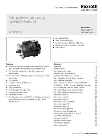
RE 91401/06.2012Bosch Rexroth AGA2FO Series 65/34Technical dataFiltration of the hydraulic fluidSizes 250 to 1000To ensure the functional reliability of the axial piston unit, a gravimetric analysis of the hydraulic fluid is necessary to determinethe amount of solid contaminant and to determine the cleanliness level according to ISO 4406. A cleanliness level of atleast 20/18/15 is to be maintained.At very high hydraulic fluid temperatures (90 C to maximum115 C), a cleanliness level of at least 19/17/14 according toISO 4406 is necessary.If the above classes cannot be achieved, please contact us.5Differential pressure p [bar]Finer filtration improves the cleanliness level of the hydraulicfluid, which increases the service life of the axial piston unit.The case pressure must be equal to or higher than the ambientpressure.Differential pressure p [bar]NG10, 12, 16NG23, 28, 32NG45NG80, 903NG107, 1252NG56, 63NG160, 1801NG2000NG500210500100015002000Speed n [rpm]2500Temperature rangeThe FKM shaft seal may be used for case drain temperaturesfrom -25 C to 115 C.NoteFor application cases below -25 C, an NBR shaft seal isrequired (permissible temperature range: -40 C to 90 C).State NBR shaft seal in plain text when ordering.Please contact us.Direction of flowDirection of rotation, viewed on drive shaft403The values are valid for an ambient pressure pabs 1 bar.The service life of the shaft seal is influenced by the speed ofthe axial piston unit and the case drain pressure (case pressure). The mean differential pressure of 2 bar between thecase and the ambient pressure may not be enduringly exceeded at normal operating temperature. For a higher differentialpressure at reduced speed, see diagram. Momentary pressurespikes (t 0.1 s) of up to 10 bar are permitted. The service lifeof the shaft seal decreases with an increase in the frequency ofpressure spikes.Sizes 10 to 2005NG355NG710, 10000Shaft sealPermissible pressure loadingNG2504clockwisecounter-clockwiseS to BS to ALong-life bearingSizes 250 to 1000For long service life and use with HF hydraulic fluids. Identicalexternal dimensions as motor with standard bearings. Subsequent conversion to long-life bearings is possible. Bearing andcase flushing via port U is recommended.Flushing flow (recommended)1000 2000 3000 4000 5000 6000 7000 8000Speed n [rpm]NG2503555007101000qv flush (L/min)1016161616
6/34Bosch Rexroth AGA2FO Series 6RE 91401/06.2012Technical dataOperating pressure rangeDefinitionPressure at service line port A or BNominal pressure pnomThe nominal pressure corresponds to the maximum designpressure.(operating with mineral oil)Size 5Nominal pressure pnom 315 bar absoluteMaximum pressure pmax 350 bar absoluteSingle operating period 10 sTotal operating period 300 hSizes 10 to 200Nominal pressure pnom 400 bar absoluteMaximum pressure pmax 450 bar absoluteSingle operating period 10 sTotal operating period 300 hSizes 250 to 1000Nominal pressure pnom 350 bar absoluteMaximum pressure pmax 400 bar absoluteSingle operating period 10 sTotal operating period 300 hMaximum pressure pmaxThe maximum pressure corresponds to the maximum operating pressure within the single operating period. The sum of thesingle operating periods must not exceed the total operatingperiod.Minimum pressure (high-pressure side)Minimum pressure at the high-pressure side (A or B) which isrequired in order to prevent damage to the axial piston unit.Minimum pressure (inlet)Minimum pressure at suction port S (inlet) which is required inorder to prevent damage to the axial piston unit. The minimumpressure is dependent on the speed of the axial piston unit(see diagram on page 7).Rate of pressure change RAMaximum permissible rate of pressure rise and reduction during a pressure change over the entire pressure range.t2tnt1Single operating periodMaximum pressure pmaxNominal pressure pnomRate of pressure change RA maxWithout pressure-relief valve 16000 bar/spnomPressure pMinimum pressure (high-pressure side) 25 bar absolutePressure pDtMinimum pressure (high-pressure side)DpTime tTotal operating period t1 t2 . tnTime tPressure at suction port S (inlet)Minimum pressure pS min 0.8 bar absoluteMaximum pressure pS max 30 bar absoluteNoteValues for other hydraulic fluids, please contact us.
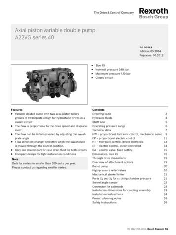
RE 91401/06.2012Bosch Rexroth AGA2FO Series 67/34Technical dataTable of values (theoretical values, without efficiency and tolerances; values rounded)SizeDisplacement geometric,per revolutionSpeed maximum1)NGVgnnomnmaxFlow at nnomPower 5656.163638080.4rpm5600 3150 3150 3150 2500 2500 2500 2240 2000 2000 1800rpm8000 6000 6000 6000 4750 4750 4750 4250 3750 3750 065748422253438475368758496Δp 350 barPkW14.54)Δp 400 barPkW–Δp 350 barTNm24.74)576789128157178254313351448Δp 400 .562.933.124.185.946.258.73Torque3)at Vg andcRotary stiffnesskNm/rad 0.63Moment of inertia for rotary group JGRkgm20.00006 0.0004 0.0004 0.0004 0.0012 0.0012 0.0012 0.0024 0.0042 0.0042 0.00725000Maximum angular accelerationarad/s2Case volumeVLMass (approx.)mkgSizeNGVgcm3rpm1800 1600 1600 1450 1450 1550 1500 1320 1200 1200 950Displacement geometric,per revolutionSpeed 0180200250355500710100090106.7 125160.4 1802002503555007101000rpm3350 3000 3000 2650 2650 2750 1800 1600 1500 1500 1200qVL/min162171200233261310Δp 350 barPkW95100117136152Δp 400 barPkW108114133155174Δp 350 barTNm501594696893Δp 400 barTNm5736797961021kNm/rad 9.1411.211.917.4Flow at nnomPower at2)5000 5000 5000 6500 6500 6500 14600 ��–100311141393197827853955 557011461273––––18.257.373.196.1Torque3)at Vg andRotary stiffnesscMoment of inertia for rotary group JGRkgm20.0072 0.0116 0.0116 0.0220 0.0220 0.0353 0.061 0.102–1442703240,1780.550.55Maximum angular accelerationarad/s260004500 4500 3500 3500 11000 10000 8300 5500 4300 4500Case volumeVL0.550.80.81.11.12.72.53.54.288Mass (approx.)mkg233232454566731101553253362)3)4)The values are valid:- at an absolute pressure pabs 1 bar at suction port S- for the optimum viscosity range fromnopt 16 to 36 mm2/s- with hydraulic fluid based on mineral oilsMaximum speed (limiting speed) with increased inlet pressurepabs at suction port S, see adjacent diagram.Torque without radial force, with radial force see page 8Torque at Δp 315 barNoteOperation above the maximum values or below the minimum values may result in a loss of function, a reduced service life or in thedestruction of the axial piston unit. Other permissible limit values,with respect to speed variation, reduced angular acceleration as afunction of the frequency and the permissible start up angular acceleration (lower than the maximum angular acceleration) can befound in data sheet RE 90261.4Inlet pressure pabs [bar]1)NG250 to 10003NG5 to 2002100.81.01.61.21.4Speed n / nnom1.82.0
8/34Bosch Rexroth AGRE 91401/06.2012A2FO Series 6Technical dataPermissible radial and axial forces of the drive shafts(splined shaft and parallel keyed shaft)553)10101212162323mm121220252025252530Fq 616TmaxΔp 46400146400 Fax maxN180180320320320320320500500–Fax maxN000000000Permissible axial force per bar operating pressure Fax perm/bar N/bar 380Drive shaftømm253030303030353535Fq 1820TmaxΔp 0401400512400 Fax maxN5005005006308008008008001000–Fax maxN000000000Permissible axial force per bar operating pressure Fax perm/bar N/bar 60160180SizeNGDrive shaftøforce1)Maximum radialat distance a(from shaft collar)Fqawith permissible torque permissible pressure ΔpMaximum axial force2)Fax –force1)Maximum radialat distance a(from shaft collar)Fqawith permissible torque permissible pressure ΔpMaximum axial force2)Fax –NGDrive shaftMaximum radial force1)at distance a(from shaft collar)Fqawith permissible torque permissible pressure ΔpMaximum axial force2)Fax –ømm354040404545455050Fq 202020252525TmaxΔp 0010214001146400 Fax maxN1000 1000 1000 1250 1250 1250 1600 1600 1600–Fax maxN0Permissible axial force per bar operating pressure Fax perm/bar N/bar 10.6SizeNGDrive shaftøforce1)Maximum radialat distance a(from shaft collar)Fqawith permissible torque permissible pressure ΔpMaximum axialforce2)Fax 66)Fq maxkN20.31.26)amm254152.552.567.567.5TmaxΔp permNmbar12734005)5)5)5)5)5)5)5)5)5) Fax maxN1600 2000 2500 3000 4400 4400–Fax maxN0Permissible axial force per bar operating pressure Fax perm/bar N/bar 16.71)0With intermittent operationMaximum permissible axial force during standstill or when the axialpiston unit is operating in non-pressurized condition.Conical shaft with threaded pin and woodruff key (DIN 6888)Restricted technical data only for splined shaftPlease contact us.000005)5)5)5)5)When at a standstill or when axial piston unit operating in nonpressurized conditions. Higher forces are permissible when underpressure, please contact us.NoteInfluence of the direction of the permissible axial force: Fax max Increase in service life of bearings–Fax max Reduction in service life of bearings (avoid)6)
RE 91401/06.2012Bosch Rexroth AGA2FO Series 69/34Technical dataEffect of radial force Fq on the service life of bearingsBy selecting a suitable direction of radial force Fq, the load onthe bearings, caused by the internal rotary group forces can bereduced, thus optimizing the service life of the bearings. Recommended position of mating gear is dependent on directionof rotation. Examples:Toothed gear driveϕopt.ϕopt. 70 45 200 to 1000 45 70 t opt opFlowqv TorqueT PowerP V-belt output5 to 180NGDetermining the operating characteristics optVg n ηvVg Δpopt2π T n60000 Speed in rpmηv Volumetric efficiencyηmh Mechanical-hydraulic efficiencyηt Total efficiency (ηt ηv ηmh)Counter-clockwisedirectionof rotationClockwisedirectionof rotationPressure atport BPressure atport APressure atport B Vg Displacement per revolution in cm3nClockwisedirectionof rotation[Nm]20 π ηmhΔp Differential pressure in bar [L/min]1000qv Δp600 ηt[kW]
10/34Bosch Rexroth AGA2FO Series 6RE 91401/06.2012
Bosch Rexroth AGA2FO Series 6RE 91401/06.2012Dimensions size 511/34Before finalizing your design, request a bindinginstallation drawing. Dimensions in mm.Port plate 07 – Threaded ports A/B and S at sideIllustration: cw direction of rotation (on version "ccw direction of rotation" the port plate is rotated through 180 )521)241045 45 YView YT256706248.5704851T1B, S61S6.47525 ø60 -0.046T1, T2B80Drive shaftsø15ø12.84247.3103.2M10x13)4)C Conical shaft with threaded pin and woodruff key, 3x5(DIN 6888), (tapering 1:10)ø15M4 x 0.72)3)13.5 0.012ø12 0.001B Parallel keyed shaftDIN 6885, A4x4x209.510.522.5PortsDesignation Port forStandard6)Size3)B (A)Service lineDIN 3852SSuction lineDIN 3852T1Drain lineT2Drain line1)2)3)4)5)6)7)Maximum pressure [bar]5)State7)M18 x 1.5; 12 deep350OM22 x 1.5; 14 deep30ODIN 3852M10 x 1; 8 deep3ODIN 3852M10 x 1; 8 deep3OTo shaft collarCenter bore according to DIN 332 (thread according to DIN 13)Observe the general instructions on page 34 for the maximum tightening torques.Thread according to DIN 3852, maximum tightening torque: 30 NmMomentary pressure spikes may occur depending on the application. Keep this in mind when selecting measuring devices andfittings.The spot face can be deeper than specified in the appropriate standard.O Must be connected (plugged on delivery)
12/34Bosch Rexroth AGA2FO Series 6Dimensions sizes 10, 12, 16RE 91401/06.2012Before finalizing your design, request a bindinginstallation drawing. Dimensions in mm.Port plate 06 – Threaded port A/B at side and threaded port S at rearIllustration: cw direction of rotation (on version "ccw direction of rotation" the port plate is rotated through 180 )201)645 45 9595129569915654901048ø80 -0.01940 29T1R18.224T260131147166YFlangesimilar to ISO 3019-2View YS85B (A)42.51)To shaft collar16
RE 91401/06.2012Bosch Rexroth AGA2FO Series 6Dimensions sizes 10, 12, 1613/34Before finalizing your design, request a bindinginstallation drawing. Dimensions in mm.Drive shafts222228 0.01540165Keywidth 6ø28Keywidth 87.5ø28 0.015ø25 0.0022228ø28M6x11)2)5P Parallel keyed shaftDIN 6885, AS6x6x32M6x11)2)B Parallel keyed shaftDIN 6885, AS8x7x3216227.5NG10, 12ø20 0.002Z Splined shaft DIN 5480W20x1.25x14x9gø28M10x1.51)2)A Splined shaft DIN 5480W25x1.25x18x9gSizes 10, 12, 1622.5NG10, 12M10x1.51)2)Sizes 10, 12, 164034PortsDesignation Port forStandard5)Size2)Maximum pressure [bar]3) State6)B (A)Service lineDIN 3852M22 x 1.5; 14 deep450OSSuction lineDIN 3852M33 x 2; 18 deep30OT1Drain lineDIN 3852M12 x 1.5; 12 deep3X4)T2Drain lineDIN 3852M12 x 1.5; 12 deep3O4)RAir bleedDIN 3852M8 x 1; 8 deep3X1)2)3)4)5)6)Center bore according to DIN 332 (thread according to DIN 13)Observe the general instructions on page 34 for the maximum tightening torques.Momentary pressure spikes may occur depending on the application. Keep this in mind when selecting measuring devices andfittings.Depending on installation position, T1 or T2 must be connected (see also installation instructions on pages 32 and 33).The spot face can be deeper than specified in the appropriate standard.O Must be connected (plugged on delivery)X Plugged (in normal operation)
14/34Bosch Rexroth AGA2FO Series 6Dimensions sizes 23, 28, 32RE 91401/06.2012Before finalizing your design, request a bindinginstallation drawing. Dimensions in mm.Port plate 05 – SAE flange port A/B at side and SAE flange port S at rearIllustration: cw direction of rotation (on version "ccw direction of rotation" the port plate is rotated through 180 )251)845 45 106118181182511512117884013 .56156.2701840 ø100 -0.022T1R23.2T2942144166Y190FlangeISO 3019-2View Y47.619S22.2106B (A)601)To shaft collar14
RE 91401/06.2012Bosch Rexroth AGA2FO Series 6Dimensions sizes 23, 28, 3215/34Before finalizing your design, request a bindinginstallation drawing. Dimensions in mm.Drive shafts272835 0.015M8x1.251)2)ø25 0.0027.5Keywidth 819Keywidth 86ø35ø3522286P Parallel keyed shaftDIN 6885, AS8x7x40ø3519 0.0157.5NG23, 28B Parallel keyed shaftDIN 6885, AS8x7x40ø30 0.002M8x1.251)2)22Z Splined shaft DIN 5480W25x1.25x18x9gø35M10x1.51)2)A Splined shaft DIN 5480W30x2x14x9gSizes 23, 28, 32M10x1.51)2)NG23, 2833Sizes 23, 28, 32505043PortsDesignation Port forStandardSize2)Maximum pressure[bar]3)State7)B (A)Service lineFastening thread B/ASAE J5185)DIN 131/2 inM8 x 1.25; 15 deep450OSSuction lineFastening threadSAE J5185)DIN 133/4 inM10 x 1.5; 17 deep30OT1Drain lineDIN 38526)M16 x 1.5; 12 deep3X4)T2Drain lineDIN38526)M16 x 1.5; 12 deep3O4)RAir bleedDIN 38526)M10 x 1; 12 deep3X1)2)3)4)5)6)7)Center bore according to DIN 332 (thread according to DIN 13)Observe the general instructions on page 34 for the maximum tightening torques.Momentary pressure spikes may occur depending on the application. Keep this in mind when selecting measuring devices andfittings.Depending on installation position, T1 or T2 must be connected (see also installation instructions on pages 32 and 33).Only dimensions according to SAE J518, metric fastening thread is a deviation from standard.The spot face can be deeper than specified in the appropriate standard.O Must be connected (plugged on delivery)X Plugged (in normal operation)
16/34Bosch Rexroth AGRE 91401/06.2012A2FO Series 6Dimensions size 45Before finalizing your design, request a bindinginstallation drawing. Dimensions in mm.Port plate 05 – SAE flange port A/B at side and SAE flange port S at rearIllustration: cw direction of rotation (on version "ccw direction of rotation" the port plate is rotated through 180 )321)1245 45 10820150R3013.51331001680.8150280235019 .8786340 ø125 -0.025T1T21142155179Y207FlangeISO 3019-2View Y52.425S26.2118B (A)641)To shaft collar20
RE 91401/06.2012Bosch Rexroth AGA2FO Series 6Dimensions size 4517/34Before finalizing your design, request a bindinginstallation drawing. Dimensions in mm.Drive shaftsKeywidth 8ø35 0.015ø30 0.002289.5339.5M12x1.751)2)P Parallel keyed shaftDIN 6885, AS8x7x5028ø35M12x1.751)2)Z Splined shaft DIN 5480W30x2x14x9g602735PortsDesignation Port forStandardSize2)Maximum pressure[bar]3)State7)B (A)Service lineFastening thread B/ASAE J5185)DIN 133/4 inM10 x 1.5; 17 deep450OSSuction lineFastening threadSAE J5185)DIN 131 inM10 x 1.5; 17 deep30OT1Drain lineDIN 38526)M18 x 1.5; 12 deep3X4)T2Drain lineDIN 38526)M18 x 1.5; 12 deep3O4)Air bleed38526)M12 x 1.5; 12 deep3XR1)2)3)4)5)6)7)DINCenter bore according to DIN 332 (thread according to DIN 13)Observe the general instructions on page 34 for the maximum tightening torques.Momentary pressure spikes may occur depending on the application. Keep this in mind when selecting measuring devices andfittings.Depending on installation position, T1 or T2 must be connected (see also installation instructions on pages 32 and 33).Only dimensions according to SAE J518, metric fastening thread is a deviation from standard.The spot face can be deeper than specified in the appropriate standard.O Must be connected (plugged on delivery)X Plugged (in normal operation)
18/34Bosch Rexroth AGA2FO Series 6Dimensions sizes 56, 63RE 91401/06.2012Before finalizing your design, request a bindinginstallation drawing. Dimensions in mm.Port plate 05 – SAE flange port A/B at side and SAE flange port S at rearIllustration: cw direction of rotation (on version "ccw direction of rotation" the port plate is rotated through 180 )321)1045 45 1172015002310714287.8195013.516.87078R301503140 ø125 -0.025T1T21150171Y195225FlangeISO 3019-2View Y52.425S26.2128B (A)681)To shaft collar23
RE 91401/06.2012Bosch Rexroth AGA2FO Series 6Dimensions sizes 56, 6319/34Before finalizing your design, request a bindinginstallation drawing. Dimensions in mm.Drive shafts32274028Keywidth 89.5ø40M12x1.751)2)Keywidth 10 0.015 0.018ø40289.533289.5P Parallel keyed shaftDIN 6885, AS8x7x50ø30 0.002B Parallel keyed shaftDIN 6885, AS10x8x50ø35 0.002M12x1.751)2)289.5NG56ø40Z Splined shaft DIN 5480W30x2x14x9gø40M12x1.751)2)A Splined shaft DIN 5480W35x2x16x9gNG56, 63M12x1.751)2)NG5638NG56, 63606035PortsDesignation Port forStandardSize2)Maximum pressure[bar]3)State7)B (A)Service lineFastening thread B/ASAE J5185)DIN 133/4 inM10 x 1.5; 17 deep450OSSuction lineFastening threadSAE J5185)DIN 131 inM10 x 1.5; 17 deep30OT1Drain lineDIN 38526)M18 x 1.5; 12 deep3X4)T2Drain lineDIN38526)M18 x 1.5; 12 deep3O4)RAir bleedDIN 38526)M12 x 1.5; 12 deep3X1)2)3)4)5)6)7)Center bore according to DIN 332 (thread according to DIN 13)Observe the general instructions on page 34 for the maximum tightening torques.Momentary pressure spikes may occur depending on the application. Keep this in mind when selecting measuring devices andfittings.Depending on installation position, T1 or T2 must be connected (see also installation instructions on pages 32 and 33).Only dimensions according to SAE J518, metric fastening thread is a deviation from standard.The spot face can be deeper than specified in the appropriate standard.O Must be connected (plugged on delivery)X Plugged (in normal operation)
20/34Bosch Rexroth AGA2FO Series 6Dimensions sizes 80, 90RE 91401/06.2012Before finalizing your design, request a bindinginstallation drawing. Dimensions in mm.Port plate 05 – SAE flange port A/B at side and SAE flange port S at rearIllustration: cw direction of rotation (on version "ccw direction of rotation" the port plate is rotated through 180 )321)45 45 1321020165R2916541012213.51816227.89957.25 2868340 ø140 -0.025T1T21163196224257YFlangeISO 3019-2View Y58.732S30.2138B (A)731)To shaft collar25
RE 91401/06.2012Bosch Rexroth AGA2FO Series 6Dimensions sizes 80, 9021/34Before finalizing your design, request a bindinginstallation drawing. Dimensions in mm.Drive shafts323745289.5Keywidth 10ø45M12x1.751)2) 0.018Keywidth 1238 0.0183612ø45289.5P Parallel keyed shaftDIN 6885, AS10x8x56ø35 0.002B Parallel keyed shaftDIN 6885, AS12x8x56ø40 0.002M12x1.751)2)12ø45M16x21)2)36Z Splined shaft DIN 5480W35x2x16x9gNG8043A Splined shaft DIN 5480W40x2x18x9gNG80, 90M16x21)2)NG80ø45NG80, 90707040PortsDesignation Port forStandardSize2)Maximum pressure[bar]3)State7)B (A)Service lineFastening thread B/ASAE J5185)DIN 131 inM12 x 1.5; 17 deep450OSSuction lineFastening threadSAE J5185)DIN 131 1/4 inM10 x 1.5; 17 deep30OT1Drain lineDIN 38526)M18 x 1.5; 12 deep3X4)T2Drain lineDIN38526)M18 x 1.5; 12 deep3O4)RAir bleedDIN 38526)M12 x 1.5; 12 deep3X1)2)3)4)5)6)7)Center bore according to DIN 332 (thread according to DIN 13)Observe the general instructions on page 34 for the maximum tightening torques.Momentary pressure spikes may occur depending on the application. Keep this in mind when selecting measuring devices andfittings.Depending on installation position, T1 or T2 must be connected (see also installation instructions on pages 32 and 33).Only dimensions according to SAE J518, metric fastening thread is a deviation from standard.The spot face can be deeper than specified in the appropriate standard.O Must be connected (plugged on delivery)X Plugged (in normal operation)
22/34Bosch Rexroth AGA2FO Series 6Dimensions sizes 107, 125RE 91401/06.2012Before finalizing your design, request a bindinginstallation drawing. Dimensions in mm.Port plate 05 – SAE flange port A/B at side and SAE flange port S at rearIllustration: cw direction of rotation (on version "ccw direction of rotation" the port plate is rotated through 180 )401)1045 45 YFlangeISO 3019-2View Y69.938Detail: port A/B(dimensions in brackets for size 107)SB (A)35.732(25)66.7(57.2)15031.8(27.8)891)To shaft collar201904040 ø160 -0.025T1
RE 91401/06.2012Bosch Rexroth AGA2FO Series 6Dimensions sizes 107, 12523/34Before finalizing your design, request a bindinginstallation drawing. Dimensions in mm.Drive shafts50289.5Keywidth 12ø50ø50M12x1.752)3) 0.018Keywidth 14803742ø40 0.002 0.0183612P Parallel keyed shaftDIN 6885, AS12x8x634328ø45 0.002M12x1.751)2)12B Parallel keyed shaftDIN 6885, AS14x9x639.5ø50M16x21)2)36Z Splined shaft DIN 5480W40x2x18x9gNG10748.5A Splined shaft DIN 5480W45x2x21x9gNG107, 125M16x21)2)NG107ø50NG107, 1258045PortsDesignation Port forStandardSize2)B (A)Service lineSAE J5185)OFastening thread B/ADIN 134501 in (size 107)1 1/4 in (size 125)M12 x 1.75; 17 deep (size 107)M14 x 2; 19 deep (size 125)SSuction lineFastening threadSAE J5185)DIN 131 1/2 inM12 x 1.75; 20 deep30OT1Drain lineDIN 38526)M18 x 1.5; 12 deep3X4)T2Drain lineDIN 38526)M18 x 1.5; 12 deep3O4)Air bleed38526)M14 x 1.5; 12 deep3XR1)2)3)4)5)6)7)DINMaximum pressure State7)[bar]3)Center bore according to DIN 332 (thread according to DIN 13)Observe the general instructions on page 34 for the maximum tightening torques.Momentary pressure spikes may occur depending on the application. Keep this in mind when s
4/34 Bosch Rexroth AG A2FO Series 6 RE 91401/06.2012 Technical data Hydraulic fluid Before starting project planning, please refer to our data sheets RE 90220 (mineral oil), RE 90221 (environmentally acceptable hydraulic fluids), RE 90222 (HFD hydraulic fluids) and RE 90223 (HFA, HFB, HFC hydraulic fluids) for detailed