Transcription
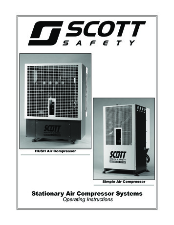
HUSH Air CompressorSimple Air CompressorStationary Air Compressor SystemsOperating Instructions
Stationary Air Compressor System Operating InstructionsContentsIMPORTANT SAFETY INSTRUCTIONS.2Safety Notations.3Safety Labels.3Limited Warranty.41 - Introduction.5HUSH Air Compressor.7Simple Air Compressor.72 - Features.7General Description.7Routine Maintenance.7Simple Air System Components.8HUSH Air System Components.9Principle of Operation.10Breathing Air Quality.10Simplified System Diagram. 113 - Starting and Operating the Stationary Air Compressor System.15Introduction.15Working with Compressed Air.15Pre-Operation Checks.16Removing the Cabinet Enclosure.16Pre-Operation Check Procedures.20Operation of the Compressor System.20Compressor Rotation.20X4 Control Panel.20Operating the Compressor .22Operating the Compressor.23Operating the Compressor Continued.24Compressor Stage Gauge Readings.24Information Button.25Operating the Compressor.25Service Notifications.25Operating the Compressor Continued.26System Tolerances and Overrides.26Use of the Purge.26Overrides.27System Shutdown.27Charging the Storage System.28Storage Cylinder Inspection.28Charging Storage Cylinders.28Cascade Volume Operation.284 - Operator Maintenance Checks.29Operator Maintenance Checks.29Service Schedules.29Condensate Container.30Electrical Fuses.30Simple Air Inlet Filter Cap.30Inlet Filter.31Purification System Moisture Indicator.31Compressor Drive Belt.315 - Additional Features.33Auxiliary Air Outlets (Standard).33Regulated Pressure Outlet (Optional).34High Pressure Outlet and Gauge.34Low Pressure Outlet and Gauge.356 - System Administrator Responsibilities.37Modify System Settings.37Perform System Service.38Calibrate the CO Monitor.397 - Index.41Maintenance Record.43Stationary Air Compressor SystemsOperating InstructionsSCOTT P/N 595134-01 REV C 1/12 2012 SCOTT Safety. SCOTT, the SCOTT SAFETY Logo, Scott Health and Safety, HUSH Air, Simple Air, X4, andSmart Fill are registered and/or unregistered marks of Scott Technologies, Inc. or its affiliates.1
Stationary Air Compressor System Operating InstructionsIMPORTANT SAFETY INSTRUCTIONSTo reduce the risk of fire, electrical shock, injury topersons, or damage when using this equipment, followbasic precautions including the following:1. Read and follow ALL user instructions andrecommended procedures and safety precautionsas provided in this manual. Failure to do so couldresult in serious injury or death.2.3.4.25.All electrical connections shall be installed by aqualified electrician in accordance with applicableelectrical codes and shall include proper groundingof the equipment.Read and follow all DANGER, WARNING, andCAUTION statements in this instruction. Failure todo so could result in serious injury or death. Thesestatements use the following pattern:6.All service must be performed by qualified trainedtechnicians. When servicing, disconnect power fromthe equipment and follow all necessary Lock-Out/Tag-Out procedures and safety procedures.DANGERDanger is used to indicate the presence of a hazard that will cause severe personal injury, death,or substantial equipment damage if the warning isignored.WARNINGWarning is used to indicate the presence of a hazardwhich may cause severe personal injury or substantial component damage if the warning is ignored.CAUTIONCaution is used to indicate the presence of a hazardwhich can cause minor personal injury or componentdamage if the warning is ignored.NOTENotes are used to notify the operator of installation, operation, or maintenance information thatis important but not hazard-related.Do not operate this equipment while under theinfluence of drugs, alcohol, or any medications orsubstances which may affect vision, dexterity, orjudgment. Users of this equipment must be in goodphysical and mental health in order to operatesafely. Do not use this equipment when fatigueprevents safe operation. Stay alert when operatingthis equipment. Inattention or carelessness whileoperating this equipment may result in seriousinjury or death.7.Hot surfaces can cause serious injury. Allow theequipment to cool before servicing.8.Establish a schedule for performing routinemaintenance as outlined in these instructions.9.Refer to the Material Safety Data Sheet (MSDS) forinstructions on the safe handling of any chemicalsused in the maintenance or servicing of thisequipment.Training is required before use of this equipment.Improper use may result in serious injury ordeath. Improper use includes, but is not limitedto, use without adequate training, disregard of thewarnings and instructions contained herein, use ofthe equipment for purposes not included in theseinstructions, and failure to inspect and maintainthe equipment.10. Moving parts can cause serious injury. Be sure allguards and covers are in place and secure beforestarting the unit.11. High pressure air is dangerous. Handle the highpressure air connections and hoses with care toprevent serious injury or death.12. The air produced by this equipment must berecertified periodically as meeting CGA Grade D orbetter breathing quality air. Regular recertificationto this standard is the responsibility of the user.13. If this equipment does not operate as described inthese instructions, DO NOT USE THE EQUIPMENT.Follow your procedures to remove the equipmentfrom service including any “Lock-out/Tag-out”procedures to prevent use of the equipment.Contact authorized personnel to inspect andservice the equipment.14. If you have any questions or concerns regarding theinstallation, use, or maintenance of this equipment,contact your authorized SCOTT distributor, orcontact SCOTT at 1-800-247-7257 (or 704-2918300 outside the continental United States) or visitour web site at www.scottsafety.com.SAVE THESE INSTRUCTIONS.
Stationary Air Compressor System Operating InstructionsSafety NotationsThe following types of safety notations are usedthroughout this manual:Danger is used to indicate the presence of a hazardthat will cause severe personal injury, death, orsubstantial equipment damage if the warning isignored.IMPORTANTFollow ALL recommended procedures andsafety precautions as provided in this manual.Federal, State and local codes mandate safetyprecautions and procedures for the handling andproduction of breathable air. Consult State and localoccupational health and industrial safety ordinancesfor additional requirements.Safety LabelsNote the safety labels that are affixed to the unit as areminder of important safety precautions. Always readand understand all safety labels prior to operating theunit. Safety labels should never be removed, defaced,or covered.Warning is used to indicate the presence of a hazardwhich may cause severe personal injury or substantialcomponent damage if the warning is ignored.Caution is used to indicate the presence of a hazardwhich can cause minor personal injury or componentdamage if the warning is ignored.NOTENotes are used to notify the operator of installation,operation, or maintenance information that isimportant but not hazard-related.Read and follow all safety labels on the unit.3
Stationary Air Compressor System - Operating InstructionsWarrantyLimited WarrantySCOTT SAFETYLimited Warranty on Scott Stationary Breathing Air Compressor ProductsScott Safety (SCOTT), a division of Scott Technologies, Inc., warrants all of its STATIONARYBREATHING AIR COMPRESSOR PRODUCTS to be free from defects in workmanship andmaterials for a period of one (1) year from the date of original manufacture by SCOTT, with theexception of its HUSH AIR COMPRESSOR PRODUCTS. SCOTT HUSH AIR COMPRESSORPRODUCTS are warranted to be free from defects in workmanship and materials for a periodof two (2) years from the date of original manufacture by SCOTT. This warranty applies to allcomponents of these products except expendable components such as oil or oil filters. SCOTT’sobligation under this warranty is limited to replacement or repair (at SCOTT’s option) of theseproducts when shown to be defective in either workmanship or materials.Only SCOTT personnel or, when directed by SCOTT, SCOTT authorized agents are permittedto perform warranty obligations. This warranty does not apply to defects or damage caused byrepairs of or alterations to SCOTT STATIONARY BREATHING AIR COMPRESSOR PRODUCTS(including HUSH AIR COMPRESSOR PRODUCTS) made by owner or any third party unlessexpressly permitted by SCOTT product manuals or by written authorization from SCOTT. Toobtain performance under this warranty, and as a condition precedent to any duty of SCOTT, thepurchaser must present such products to SCOTT, a SCOTT authorized distributor, or a SCOTTauthorized service center. Any product returned to SCOTT shall be sent FOB destination to ScottSafety (Attn. Warranty Claim Department) 4320 Goldmine Road, Monroe, NC 28111.This warranty does not apply to any malfunction of or damage to these products resulting fromaccident, alteration, misuse, or abuse, which includes and is not limited to failure to performpreventative maintenance recommended by SCOTT.THIS WARRANTY IS MADE IN LIEU OF ALL OTHER WARRANTIES, EXPRESSED OR IMPLIED,INCLUDING, BUT NOT LIMITED TO, ANY IMPLIED WARRANTY OF MERCHANTABILITY ORFITNESS FOR A PARTICULAR PURPOSE. IN ADDITION, SCOTT EXPRESSLY DISCLAIMSANY LIABILITY FOR SPECIAL, INCIDENTAL, OR CONSEQUENTIAL DAMAGES IN ANY WAYCONNECTED WITH THE SALE OR USE OF SCOTT SAFETY PRODUCTS AND NO OTHERFIRM, OR PERSON IS AUTHORIZED TO ASSUME SUCH LIABILITY.4
Stationary Air Compressor System Operating Instructions1 - IntroductionCongratulations on your purchase of a SCOTT SafetyStationary Air Compressor System. SCOTT Safety provides a full line of breathing air system components andrelated accessories for the safe production and storageof compressed breathing air.This manual provides instructions for the operation of theStationary Air compressor including the control panel,compressed air storage systems, and some optionalaccessories. Use of the charging station is covered in aseparate user instruction.These instructions are categorized by component, sinceconfigurations of breathing air systems will vary depending on selected options. Operators of these units mustbecome familiar with their particular system configuration and refer to the proper instructions as covered inthis manual.This air compressor and equipment are intended forcharging breathing air cylinders for use in respirators orself-contained breathing apparatus (SCBA). The compressor and purification system are designed to purify airto meet or exceed recognized air standards as specifiedby the Compressed Gas Association (CGA G-7.1) andNational Fire Protection Association (NFPA 1989).Proper installation of the Stationary Air Compressor System must be performed in accordance with SCOTT Safetyrequirements, for optimum performance and adequatewarranty coverage. Maintenance of the system beyondthe instructions provided herein must be performed bya SCOTT trained and certified technician.Before use, this equipment must be properly installedand inspected by a SCOTT Safety trained andcertified technician. Do not operate if the equipmenthas not been prepared by a SCOTT authorizedservice technician. Use of this equipment withoutproper set up may result in serious personal injury,death, or permanent equipment damage.For additional information regarding the design, operation, or service of the Stationary Air Compressor System,contact SCOTT Safety at 1-800-247-7257.5
Stationary Air Compressor System Operating Instructions1 - IntroductionHUSH Air CompressorSimple Air Compressor6
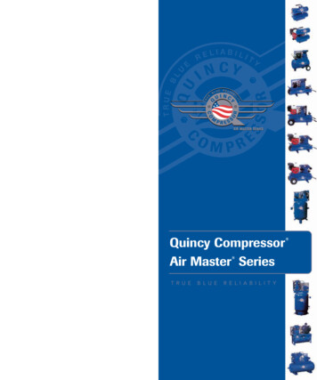
Stationary Air Compressor System Operating Instructions2 - FeaturesGeneral DescriptionThe standard Stationary Air Compressor System isequipped with a heavy‑duty, three- or four-stage,air-cooled compressor. The system also includes anautomatic condensate drain system, compressor stagegauge panel, and a low oil shut-off switch. When properlymaintained, the air purification system is designed toprovide breathing air that meets Grade D/E of the CGAbreathing air standard G-7.1. Be sure you understand thebreathing air requirements and maintenance proceduresof your respiratory protection program.When ordering spare parts, note the unit model andcompressor serial number. This information will avoiddelays and the possibility of incorrect parts beingprovided. The Stationary Air Compressor System modelnumber is stamped on the system identification tag. Thelocation of this tag will vary with the system model. Thecompressor serial number is stamped on a metal plateattached to the crankcase of the compressor.Additional accessories available for the Stationary AirCompressor System include a Cab Air cabinet enclosure,choice of system controller, breathing air cylinder fillstation and compressed air storage cylinders.These Operating Instructions apply to the followingSCOTT Breathing Air Compressor Systems:The Simple Air Compressor Systems5 HP5000 psiThree Stage7.5 HP5000 psiThree Stage7.5 HP6000 psiFour Stage10 HP6000 psiFour StageThe HUSH Air Compressor System20 HP6000 psiFour Stage15 HP6000 psiFour StageIllustrations of the two compressors follow on the nextpages.Compressor System Model Number(Actual appearance and location may vary)To order replacement components, call 1-800-247-7257or contact an authorized SCOTT Safety distributor.Routine MaintenanceThe reliable operation of this equipment depends onproper care and routine maintenance.The operator must be trained by an authorized SCOTTSafety technician in the proper operation of thestationary breathing air system. The operator must read,understand, and adhere to all safety precautions andpre-operation tasks as described in this manual.Use only SCOTT approved parts and supplieswhen servicing this compressor system. Use ofunapproved parts or supplies may result in reducedperformance or damage to the equipment.All scheduled maintenance beyond the scope of thismanual must be noted by the operator to be performedby a SCOTT trained and certified service technician.A Maintenance Record page is provided in thisinstruction.7
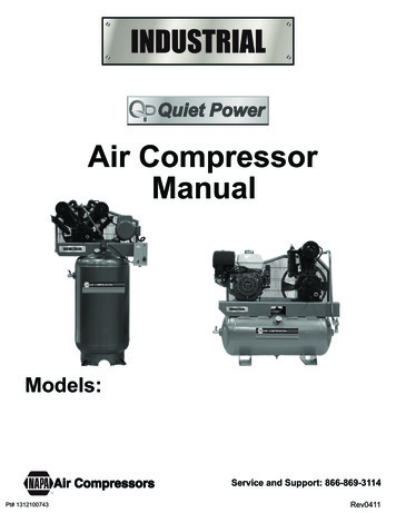
Stationary Air Compressor System Operating Instructions2 - FeaturesSimple Air System Components112233541)Stage Gauges (Four Stage Compressor shown)2)Purification Filters3)Electric Box (Fuse Location)4)Fuses (2)5)Condensate ContainerNOTEThe actual appearance of the equipment may varydepending on the model and options installed.81)Inlet Filter2)Oil Fill Cap3)Interstage Relief ValveModel Number - Open Units
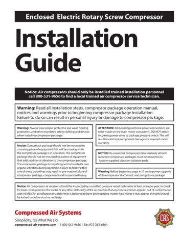
Stationary Air Compressor System Operating Instructions2 - FeaturesHUSH Air Compressor System Components31123421)Purification Filters2)Condensate Container3)Pressure Relief Valve4)Electrical Box (Fuse Location)1)Inlet Filter2)Stage Gauge Panel3)Oil Fill CapCompressor Serial NumberHUSH Air Pressure Relief Valves9
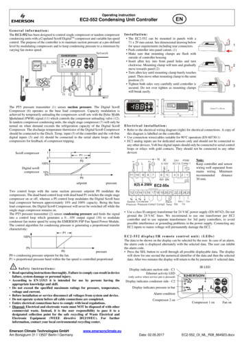
Stationary Air Compressor System Operating Instructions2 - FeaturesPrinciple of OperationThe production of high-pressure breathing air can bedivided into four categories:Compression - accomplished by a multi-stagecompressor assembly.Purification - accomplished by mechanical filtration andchemical purification.Storage - accomplished in DOT or ASME certifiedstorage cylinders.Handling and Charging - accomplished with equipmentused to connect and fill the breathing air cylinders.Electrical current (available as 208 or 230 VAC singlephase, or 208, 230, or 460 VAC, 3-phase) deliverspower to a motor that drives the compressor through aVee-Belt.Ambient air is filtered and then compressed to themaximum system pressure in three or four stages. Eachstage is equipped with a standard safety valve, setslightly above the normal working pressure of the stage;the valve will release high pressure air to protect thesystem in case of mechanical failure. All stage pressurereadings are indicated on the front panel (Simple Air) oron the compressor gauge panel (HUSH Air).An air-circulating fan mounted on the flywheel is usedto blow cooling air through the four stage air coolersand over the compressor head cooling fins. Air passingthrough the air coolers serves to lower the air temperatureto increase compressor efficiency.Moisture separators continuously remove moisturefrom the compressor intercooler and aftercooler aircircuits. During normal operation, the dump solenoidvalves are activated automatically every 15 minutes.The condensate container collects the moisture fromthe moisture separators; the container must be manuallydrained when full.When the discharge pressure reaches the maximumpreset level, the compressor is unloaded. The moisturetraps open, and the compressor continues to run withoutcompressing air. Prior to stopping, the compressorwill run unloaded through a cool-down cycle whiledraining the moisture separators and cooling down thecompressor stages. This prevents the development ofrust in the compression cylinders and also provides foran unloaded compressor restart.After the pressurized air leaves the compressor, it passesthrough a multi-stage purification system. The number ofstages depends on the horse power, and therefore theair output capacity of the compressor. The higher theair output, the more purification elements are needed.The purification system further dries the air and removesother impurities.10From the purification system, the air can go directly tocharging breathing air cylinders, or can be sent to highpressure storage cylinders and maintain the pressure inthe storage for charging several breathing air cylindersbefore the compressor restarts to refill the storage.Breathing Air QualityThe X4 Controller is available in several configurations.The full-feature controller model includes monitors forboth Carbon Monoxide (CO) and Moisture (Dew Pointor DP) levels along with the standard monitors for highdischarge air temperature and low oil conditions. Thesemonitors give an indication of the quality of the breathingair being produced. If monitored conditions are out oftolerance, the controller emits a visual and audible alarmand will subsequently shut down the compressor.On compressor systems where the SCOTT CO or DewPoint monitors are not installed or operational, it is theresponsibility of the organization using this equipment toestablish procedures to assure the breathing air qualityto the end user in the time between the routine airsamples. Failure to establish procedures to monitor thebreathing air quality could result in undetected problemsthat could lead to production of air that does not meetthe CGA breathing air standards cited on Page 7 of thisinstruction.On compressor systems where the CO or Dew Pointmonitors are not installed, it is also the responsibilityof the organization using this equipment to establishprocedures or to install test equipment to assurethe breathing air quality to the end user in the timebetween the routine air samples. Failure to establishprocedures or to install test equipment to monitorthe breathing air quality could result in undetectedproblems that could lead to production of air thatdoes not meet the breathing air standards whichcould lead to serious injury or death of the respiratorusers.It is also the responsibility of the System Administratorto inform the Operator what features are installedand enabled and to train the Operator in their use. Itis the Operator’s responsibility to notify the SystemAdministrator of any alarms or shutdown warnings thatoccur during the operation of the compressor system.
Stationary Air Compressor System Operating Instructions2 - FeaturesSimplified System DiagramNOTE: The illustration represents a simplified diagramfor the purposes of basic operation. Outlets, connectionpoints, and optional equipment are not shown.11
Stationary Air Compressor System Operating Instructions2 - FeaturesX4 ControllerThe Stationary Air Compressor System is equipped withan X4 Controller to start and stop the compressor and toprovide information about the compressor’s performanceand condition to the Operator. The X4 Control Panelfeatures an LCD display, a key pad, and warning lightsfor ALARM, SHUTDOWN, SERVICE, and PURGE.T 104 CO 0DP -80 FCondition NormalCompressor will Stop whenStorage is FullFour models of the X4 are available for a Stationary Aircompressor system:The Basic controller has warning indicators for highdischarge air temperature and low oil conditions.The CO Only controller has the same features asthe Basic controller but adds a monitor for high carbonmonoxide (CO) levels in the breathing air.The Dew Point Only controller has the same featuresas the Basic controller but adds a monitor for excessivemoisture levels (Dew Point or DP).12The Full Feature controller includes BOTH the CarbonMonoxide (CO) monitor AND the moisture level monitor(Dew Point or DP) along with warning indicators for highdischarge air temperature and low oil conditions.On X4 Controllers equipped with either CO orDew Point monitoring, the following featureswill be present:It is the responsibility of the System Administrator toinform the Operator what features are installed andenabled and to train the Operator in there use. It isthe Operator’s responsibility to notify the SystemAdministrator of any alarms or shutdown warnings theoccur during the operation of the compressor system.1)Flow Control Dial2)Air Flow Adjustment EyeNOTEIf the CO or Dew Point monitor is not installed onyour system, the X4 Controller will display “N/A”after the parameter on the LCD screen.On compressor systems where the CO or Dew Pointmonitors are not installed, it is also the responsibilityof the organization using this equipment to establishprocedures to assure the breathing air quality to theend user in the time between the routine air samples.Failure to establish procedures to monitor the breathingair quality could result in undetected problems that couldlead to production of air that does not meet the breathingair standards.If monitored conditions are out of tolerance, the controlleremits a visual and audible alarm and will subsequentlyshut down the compressor.The controller allows the system to run in either AUTOor MANUAL mode. In AUTO mode, the compressorwill automatically restart when storage pressure dropsapproximately 500 psi below the maximum systempressure. When in MANUAL mode, the compressor stopsafter purging and must be restarted manually.PurificationAfter leaving the compressor, compressed air passesthrough a series of purification chambers.The Stationary Air compressor is available rated for either5000 or 6000 psi working pressure to purify up to 84,000SCF of air (based on 70 F/21 C inlet temperature). Amechanical filter separator removes oil, moisture, andairborne foreign particles from the pressurized air. Theremaining purifier chambers remove additional chemicalparticles from the air before being released for use.After the air has been compressed and purified, it isdirected either to a charging station for filling breathingair cylinders or to storage cylinders, depending uponsystem options.12
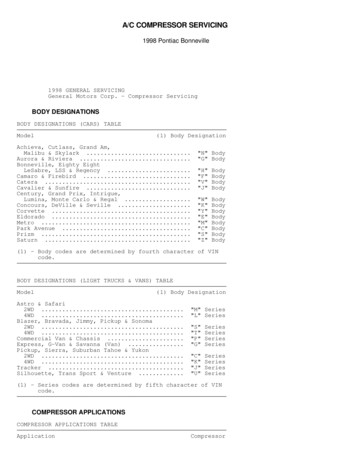
Stationary Air Compressor System Operating Instructions2 - FeaturesStorageThe Stationary Air compressor may be configured to directcompressed air to an optional air storage system.Storage systems can meet peak demands for compressedair without the requirement of full-time compressoroperation. Stored air can also be used to carry onoperations in the event of compressor failure, lossof power to run a compressor, or in areas wherecompressors are not available.Storage CylindersA standard air storage system consists of a set of two,four, or six ASME or DOT certified storage cylinders.ASME cylinders are designed and constructed inaccordance with Section Eight of the American Society ofMechanical Engineers (ASME) code for Unfired PressureVessels. ASME cylinders may be installed vertically orhorizontally, depending upon system options. All storagesystems are equipped with a service valve and a reliefdevice.DOT cylinders meet the standards set by the Departmentof Transportation (DOT); these cylinders are generallylighter in weight (approximately 200 lbs each) and arealways installed vertically.Each DOT cylinder stores 509 standard cubic feet at6000 psi. Each ASME cylinder has the capacity to store454 standard cubic feet (SCF) at 5000 psi, or 525 SCFat 6000 psi.DOT cylinders must be visually inspected andhydrostatically tested by a licensed cylinder re-testerin accordance with the appropriate US Departmentof Transportation (DOT) specification or applicableDOT exemption, or in accordance with the appropriateTransport Canada (TC) Permit of Equivalent Level ofSafety. Depending on when the DOT storage cylinderswere purchased, this may be five (5) or ten (10) years.Verify the required re-test schedule for your DOT storagecylinders and establish a procedure for haveing thecylinders re-tested to that schedule.The date of manufacture marked on the cylinder is alsothe date of the first hydrostatic test. Subsequent testdates are indicated by labels affixed to the cylinder.If the required hydrostatic test date has expired forthe DOT cylinder, DO NOT USE the cylinder. Notify asupervisor or other certified personnel responsible forcylinder inspection.ASME cylinders do not require hydrostatic testing, butinclude a drain valve and gauge. If installed, safety valveson ASME cylinders must be tested on an annual basis.ASME safety valves can by identified by a tag or labelshowing traceability to the National Bureau of Standards(NB) and a tamper evident seal. Some SCOTT storagesystems with ASME storage cylinders are protected bysingle use rupture disks that cannot be tested.Refer to specific ASME or DOT safety standards foradditional testing information.DOT Storage CylindersBulk vs. Cascade Storage SystemsStorage receivers can be configured together as a singlebulk storage bank, or separately in a cascade system.When configured as a single bank, cylinders are “piped”together into a single volume. Storage pressure isindicated by a single gauge on the main control panel.Cylinders in a cascade system are plumbed separatelywhich allows for more efficient use of compressed airsince each cylinder can be isolated when accessingsystem air. With a manual cascade system, a cascadepanel with individual fill control valves and gauges foreach cylinder or bank require the operator to control theselection and flow of air from each bank.Manual Cascade Air Storage - Control PanelWith the SCOTT Smart Fill Auto Cascade cylinderfilling system, the selection and flow are managedautomatically. Instructions for use of a cascade storagesystem are included in the separate procedures for fillingbreathing air cylinders.13
Stationary Air Compressor System Operating Instructions2 - FeaturesHandling and ChargingAuxiliary Air Outlets and GaugesCompressed air may be directed to a charging stationfor charging breathing air cylinders. Two SCOTT modelsare available: the RevolveAir and the Guardian. Bothstations include a control panel, a secure fragmentationchamber, and rigid “fast-attach” charge adapters for quickand safe breathing air cylinder charging.The standard charging station control panel is equippedwith two auxiliary air outlets that can be used to serve avariety of compressed air needs. These outlets may belocated on the front or on the back of the control panel.The RevolveAir charging station is identified by aturntable device that allows for simultaneous charging oftwo breathing air cylinders to any pre-selected pressurenot to exceed the rated pressure of the cylinders beingcharged. Meanwhile, a second set of cylinders canbe attached and made ready on the outside of thechamber.The Guardian is a closed-lid, bottom vent, total containmentfill station. The design allows for simultaneous charging oftwo breathing air cylinders to any pre-selected pressurenot to exceed the rated pressure of the cylinders beingcharged.Separate User Instructions are provided with the selectedCharging Station.Dual Pressure RegulatorSome SCOTT charging stations may be equipped withan optional Dual Pressure Regulator for controllingthe maximum fill pressure when charging breathing aircylinders. The dual pressure regulator allows for twostandard fill pressure settings for breathing air cylinders,such as 2216 psi and 4500 psi.The two pressure sett
Stationary Air Compressor System Operatin Instructions General Description The standard Stationary Air Compressor System is equipped with a heavy-duty, three- or four-stage, air-cooled compressor. The system also includes an automatic condensate drain system, compressor stage gauge panel, and a low oil shut-off switch. When properly