Transcription
Scanning Microscopy Vol. 11, 1997 (Pages 171-177)Scanning Microscopy International, Chicago (AMFRadonO’Hare),transformIL 60666techniquesUSA0891-7035/97 5.00 .25RADON TRANSFORM TECHNIQUES FOR ALIGNMENT AND THREE-DIMENSIONALRECONSTRUCTION FROM RANDOM PROJECTIONSMichael Radermacher*Wadsworth Center, New York State Department of Health andDepartment of Biomedical Sciences, State University of New York, Albany, NYAbstractIntroductionSince their inception, three-dimensional reconstruction techniques have been based on the theory of Radontransforms. Only much later were Radon transformsrecognized as powerful tools for image processing andpattern recognition. Techniques like the common linestechnique for finding the orientation of projections of highlysymmetrical particles can easily be translated into atechnique that uses Radon transforms. Radon transformshave the advantage of being real valued which simplifiesmany interpolation steps. Correlation techniques have beendeveloped for alignment of a single noisy projection relativeto a three-dimensional model and many ideas originally setforward in previous work by the author have been realized.These include simultaneous rotational-translationalalignments, iterative refinements of three-dimensionalreconstructions and a Two-step Radon Inversion Procedure(TRIP).For a three-dimensional reconstruction from projections the orientation of the projections in relation to acommon coordinate system must be known. In tomographicreconstructions of single objects - e.g., centrosomes in thicksections or individual macromolecules - from single-axis orconical tilt series, the orientation of the projections is knownfrom the microscope’s goniometer reading. Here, the mainalignment problem is a translational alignment relative to acommon origin [7]. In a reconstruction from projections ofmultiple copies of the same macromolecule, the orientationcannot be determined solely from the goniometer reading.The method of reconstruction from a random conical tiltseries [13, 15] still takes advantage of the fact that mostmacromolecules attach to the carbon support of thespecimen in a preferred orientation, which again relates oneangle to the goniometer tilt. The second angle here can befound through rotational alignment techniques applied to a0 image of the specimen. If a tilt series is not available andthe molecule does not exhibit preferred orientation, thenthe orientation of a particle in any given projection must befound by information contained in the image. The commonlines method developed by Crowther et al. [3] solved thisproblem for particles with a high degree of symmetry. Foricosahedral symmetry the Fourier transform of oneprojection intersects with up to 59 symmetry-relatedprojections. The pattern of common lines can be found inone projection as each projection also represents allsymmetry related images. This pattern determines theorientation of the projection.Projectionsofasymmetrical particles do not contain common lines withinone image. However, the Fourier transforms of any twoprojections of the same object share at least one line, whichlies along the direction of the common tilt axis. If three noncolinear common lines among three projections can befound, then these three lines determine uniquely - asidefrom a mirror operation - the orientation of these threeprojections in space [5, 6, 18].Whereas the original method for finding commonlines had been developed using Fourier techniques, thereare advantages in replacing some of the analysis byKey Words: Radon transform, image processing, alignment,three-dimensional reconstruction, electron microscopy.*Address for correspondence:M. RadermacherMax-Planck Institute for BiophysicsDepartmen of Structural BiologyHeinrich-Hoffmann-Straße 7D-60528 Frankfurt/M, GermanyTelephone number: 49-69-9676 9352FAX number 49-49-9676 9359E-mail: michael@biophys.mpg.de171
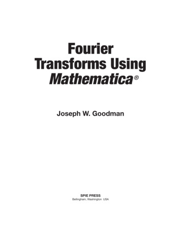
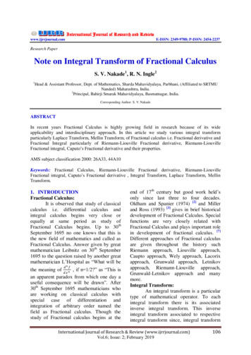
M. Radermacheroperations on Radon transforms [12, 16].TheoryThe three-dimensional Radon transform is definedas fˆ p, ξ f (r ) δ p -ξ r d r( )()(1)where δ(p-ξ r) specifies a plane over which the integrationis carried out and ξ is the unit vector that determines thedirection of this plane. For the two-dimensional Radontransform, ξ and r are replaced by two-dimensional vectorsand the integration becomes a line integration instead of anintegration over planes.Radon transforms and Fourier transforms are closelyrelated. The two- or three-dimensional Fourier transformcan be calculated from the two- or three-dimensional Radontransform by a one-dimensional radial Fourier transform fˆ p, ξ F sξ e 2πsp ds( )( )(2)with F(sξ) being the two- or three-dimensional Fouriertransform of f(r) in polar coordinates. The projection theoremknown from Fourier theory is also valid for Radon transforms[4].A further theorem is the shifting property of Radontransforms. If f(r-a) is the function f shifted by a, then itsRadon transform is f (r - a ) δ p - ξ a dr (3) ˆ f (q ) δ p - ξ a - ξ q dq f p - ξ a,ξMany convolutions that have kernels of two or threedimensions when applied to a real space object becomeone-dimensional kernels when applied to Radon transforms.AlignmentThe rotational and translational alignment betweentwo images can be found from the cross-correlation of theirRadon transforms. Let (p,ξ), with ξ (cos (ε), sin(ε)), bethe the Radon transform of a reference image and let (p,ξ)be the Radon transform of the image that is to be alignedwith respect to . Let be rotated relative to by an angle α0and shifted by r0 (r0 cos(η0), r0 sin(η0)). The crosscorrelation function(())(c(α, r, η) (p, ) (p-r sin(ε η),ε α) dp dεFigure 1. Simultaneous translational/rotational alignmentof an image series relative to a fixed reference. Both referenceand image series (a) are Radon transformed (b), followed bya one-dimensional Fourier transform (c) along p (Eqn. 2).The Fourier Radon transform of the image is multiplied withthe Fourier Radon transform of the reference (d) followedby a one-dimensional inverse Fourier transform (e). A seriesof cross-correlation coefficients is calculated by summationover sine curves (f). Their amplitudes correspond to thesize of the shift and their phases to the shift direction. Thesecross-correlation coefficients are stored in the crosscorrelation file (g) (see Figure 2). The lines in the FourierRadon transform of the image are then permutated and thecalculations repeated for the next orientation, starting atstep (d).)The alignment procedure can be directly extendedto an alignment of projections relative to a three-dimensionalreference. The cross-correlation function then becomesc(φ, θ, α, r, η) (4) ′φ,θ(p, ) (p-r sin(ε η),ε α) dp dεthen has its maximum at (α0, r0, η0).′φθ is the cross-section through the three-dimensional172(5)
Radon transform techniquesTable 1. Comparison of average residual shifts, rotations and resolution limits.Comparison of average residual shifts (in pixels), rotations (in degrees) and resolution limits of the resulting average imagesafter a traditional rotational/translational alignment versus a simultaneous rotational/translational alignment (DPR: DifferentialPhase Residual; FRC: Fourier Ring Correlation). Test 1 shows the residuals after several steps of alignment, i.e., centering,dynamic reference alignment followed by fixed reference alignment. Test 2 shows residuals after a single fixed referencealignment.Radon transform at angles (φ, θ).For higher computational efficiency the Radontransform of the reference as well as those of all projectionsare Fourier transformed (Fig. 1). The cross-correlation iscalculated by line-by-line multiplication of Fourier-Radontransforms followed by inverse radial Fourier transformation.The integration over ε is done as a summation across thelines along curves c(ε) r sin(ε η).The rotation of the projections can be applied totheir Fourier-Radon transforms by a commutation of lines.Shifts can also be applied to the Fourier-Radon transformsby phase multiplication. If the Radon transform is calculatedwith an angular increment of φ, the number of samplingpoints per line is K, and the shift vector is r (cos(η),sin(η)),then the phase factor P for the Fourier coefficient k in line nisP exp [2 π i r cos((n-1) φ-η) k/K]dimensions.In three dimensions the alignment with dynamicreference is done in the following way: The lines that formthe intersection of the projection through the threedimensional Radon transform are determined. Each line ismultiplied by its averaging index. The corresponding line ofthe current projection is subtracted, the index reduced by 1,and the result divided by the new averaging index. Theorientation and relative position of the Radon transform ofthe projection is determined according to equation (5) andis averaged back into the three-dimensional Radontransform using the reverse of the procedure for subtraction.Lines that have an averaging index of 0 are skipped in thecalculation of the cross-correlation.For three-dimensional alignment relative to a fixedreference, only the cross-correlation function (eqn. 5) isused.The alignment procedures that use a dynamicreference are iterated. As stated earlier, for highercomputational efficiency each image is Radon transformed,followed by a radial Fourier transform before the alignment.Averaging in two and three dimensions is then done inFourier space.The translational alignment is implemented with afixed accuracy, currently 1 pixel. The shift coordinates aredetermined in polar coordinates. For a 1 pixel shift, 8 crosscorrelation coefficients are calculated for angles η (eqn. 2)with values of 0 , 45 , 90 , 135 , 180 , 225 and 270 . For a2 pixels shift the 360 angular range is divided into 16intervals, and for an n-pixel shift into n 8 intervals. Figure 2shows a cross-correlation function of a two-dimensionalsimultaneous translational/rotational alignment with amaximum at an angle of 78 and a shift of 9 (cos 70 , sin70 ).(6)Like the traditional rotational and translationalalignment algorithm the new algorithm can also beimplemented either as alignment algorithm relative to a fixedreference or as an iterative algorithm with a dynamicreference. (Note: Originally this method had been calledreference free alignment [11]). In the latter case one image ischosen as the first reference and the next image is alignedto this reference and added to create a new reference for thefollowing image. Alternatively an average in two dimensionsor a three-dimensional Radon transform is created as a firstreference from the projection series with randomly assignedangles. Whereas in two dimensions the number ofmeasurements averaged is the same for each point, in thethree-dimensional Radon transform this number varies fromone line to the next. Here, each radial line in the Radontransform has an averaging index that keeps track of thenumber of projection lines used for each line in three173
M. RadermacherThree-dimensional reconstructionTo observe the progress of the alignment in threedimensions, a fast Two-step Radon Inversion Procedure(TRIP) has been developed. The three-dimensional Radontransform as implemented is sampled on a polar grid.Whereas this sampling scheme uses more points thannecessary according to Shannon’s sampling theorem, theregular grid simplifies many calculations. The threedimensional Radon transform is calculated in two steps. Instep one, a series of projections forming a single-axis tiltseries is calculated from the three-dimensional real spacevolume. In step two, each projection is then Radontransformed in two dimensions. As a result, each twodimensional Radon transform then forms a θ-slice (zdirection) in the three-dimensional transform. The radialcoordinate increases along the line of each slice (x-direction)and the angle φ varies with y. For the inversion an r*weighted back-projection algorithm has been written. Theinversion follows the opposite sequence of the forwardRadon transform. First, two-dimensional reconstructions arecalculated for each θ-slice, which recreates the “single-axistilt series”. From this series the three-dimensional volumeis calculated by a second two-dimensional inversion in slicesperpendicular to the y-axis. This procedure is very fast andcan take as little as three minutes for a 64x64x64 reconstruction done on a VAX alphastation.The r*-weighted back-projection can easily bereplaced with other two-dimensional inversion algorithms,e.g., a moving window Shannon interpolation [9, 10] or aFourier Bessel inversion [3].The reconstruction algorithm can be used independently of the alignment procedure for a reconstruction fromrandom projections. A part of the dynamic referencealignment procedure is averaging of projections into thethree-dimensional Radon transform at given angles. Thus aseries of projections with known angles can be averagedinto a three-dimensional Radon transform, which can thenbe inverted. Like the averaging algorithm, the inversionalgorithm works for real space Radon transforms and forFourier space Radon transforms.If the sampling of the three-dimensional Radontransform is complete (i.e., there are no empty lines), thealgorithm works essentially with the same accuracy as otheralgorithms specifically written for arbitrary tilt geometry(discrepancy (e.g., [1, 2]) 12% for general geometryweighting versus 8% for the current algorithm). However,when large angular sampling gaps are present, the weightedback-projection for arbitrary geometry works better. Thedifference in performance can be easily explained. A truethree-dimensional reconstruction algorithm is able tointerpolate between measurements coming from alldirections, whereas the measurements available to thecurrent algorithm either need all be in the same θ-plane (instep 1) or all in the same y-z-plane (step 2).The reconstruction algorithm is an averaging methodin three dimensions. Thus, a number of the same errormeasures can be calculated as in other averaging procedures. Among them are a determination of the standarddeviation of every point in the three-dimensional Radontransform, which when inverted leads to an error estimatefor every pixel in the three-dimensional reconstruction.Because the averaging step can be done in real or in Fourierspace, calculations like three-dimensional Q-factors [8, 19]and spectral signal to noise ratios [17] are possible.Test Calculations and ApplicationsAlignment in two dimensionsSimultaneous translational and rotational alignmenthas been applied to a series of 448 images of the 50Sribosomal subunit prepared in vitreous ice.The new simultaneous alignment algorithm and thetraditional separate translational/rotational alignmentmethods were compared in two series of test calculations.The first test (test 1 in Table 1) consisted of three steps:First, all images were centered, as is traditionally done,by cross-correlation to the image of a low-pass filtered diskwith the approximate size of the particle [13]. Second, adynamic reference alignment was done, followed in the thirdstep by a fixed-reference alignment. The reference used wasthe average that was obtained in the previous step. Residualshifts and translations were then determined by anotherfixed reference alignment.In a second test (test 2 in Table 1) both alignmentprocedures were applied directly to the non-centered originalimages using a fixed reference. This was again followed bya second alignment step to determine residual shifts androtations.In test 1 the residual shifts turned out to be approximately the same, less than 1 pixel. One pixel was the accuracyto which the simultaneous alignment determined thetranslation. The differences are larger for the rotationalalignment, where the simultaneous alignment was moreaccurate. As expected, the difference in performance of thetwo algorithms is much larger in test 2, where thesimultaneous alignment produces average residual shiftsand rotations that are smaller by a factor of about 20. Thereare two advantages to the simultaneous alignment algorithm.One advantage is a simple time factor: an alignment withthe new algorithm takes approximately the same amount oftime as a single iteration of the non-simultaneous alignmentalgorithm. The faster performance results from not needingmultiple iterations. A second advantage is that thesimultaneous alignment algorithm when applied to a fixedreference will find the best global maximum in the rotational/translational cross-correlation function, whereas thetraditional algorithm is more prone to finding a local174
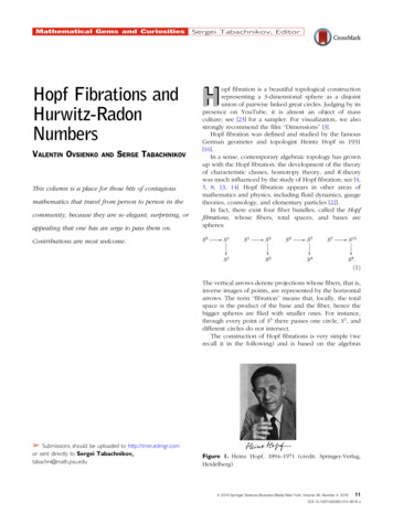
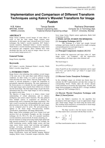
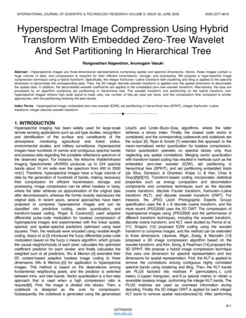
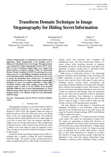
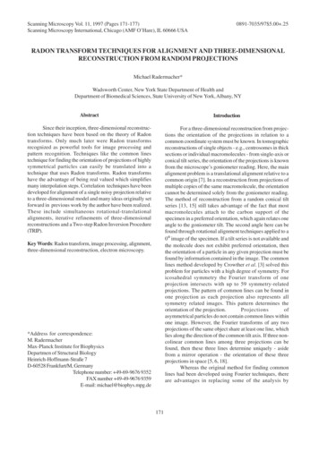
Radon transform techniquesFigure 2. Cross-correlation function from a two-dimensionalsimultaneous translational/rotational alignment. Thefunction shows bands of increasing width. The width ofeach band corresponds to the number of directions searchedfor each value r. In each band the horizontal axis is thedirection of the shift vector, and the vertical axis is therotation of the image.maximum.Three-dimensional alignment and reconstructionAs a test object a volume was created containingeleven spheres in random positions (Fig. 3). Two hundredprojections were calculated from this volume with randomangles. A different set of random angles was assigned tothese projections and a reconstruction was calculated thatessentially, because of the arbitrary angle assignment,showed no significant features. The three-dimensionalalignment procedure with dynamic reference was thenapplied. In sequence each projection was subtracted fromthe volume, the cross-correlation function (Eqn. 5) wascalculated, and the projection was averaged back into thevolume with the angles found. Figures 4, 5 and 6 show theresults of this calculation. Features already appear after thefirst iteration and the pattern of spheres appears afteriteration 7. TRIP was used in the calculation of allreconstructions shown.This example uses a noise-free data set, and it isclear that the three-dimensional dynamic reference alignmentalgorithm will not perform as well with real data. The signalto-noise ratio of Radon transforms of images of frozenhydrated samples is on the order of 0.3, and trials with rawdata thus far have not yielded convincing results. Thecurrent implementation can still be improved to make betteruse of the information present, and the noise limit of thealgorithm will be determined once these improvements havebeen implemented. It has been shown earlier [14], however,that the alignment algorithm works for a fixed-referencealignment down to a signal to noise ratio of less than 1. Thedynamic reference alignment algorithm is the firstFigure 3. Test of three-dimensional dynamic referencealignment. (a) Surface representations of the model volume,(b) Slices through the volume, perpendicular to z near thecenter, (c) Projections of the volume, (d) Selected crosssections through the three-dimensional Radon transform.The angles correspond to the angles of the projectionsshown in (c), (e) Sections through the three-dimensionalRadon transform that was created from the projections witharbitrarily assigned angles. Slices correspond to the sameθ-angles as the cross-sections shown in (d); (f) Slicesthrough the reconstruction calculated from (e). The surfacerepresentation of this volume is shown in Figure 4, panel 0.175
M. RadermacherFigure 5. Sections through the reconstruction after 1, 13and 26 iterations.Figure 4. Surface views of the volume during iteration ofthe dynamic reference alignment in three dimensions.Numbers indicate iteration. Iteration 0 is the start volumecreated from projections with arbitrarily assigned angles.implementation of the extension of this original algorithmas it was proposed in [14].Figure 6. Comparison of original volume (a) andreconstructed volume (b) using the dynamic referencealignment method in three dimensions.ConclusionRadon transform-based methods have beenpresented that allow a reconstruction from randomprojections and provide a technique for simultaneoustranslational and rotational alignment in two and threedimensions. The simultaneous alignment worked faster andwith substantially higher accuracy than traditional methodsthat alternate between translational and rotationalalignments. Fixed-reference and dynamic-referencealignment procedures have been developed for two andthree dimensions. They have been combined with a fastRadon inversion algorithm. By itself, this algorithm canalso be used for three-dimensional reconstruction fromprojections with any set of known orientations. The firststep in building the three-dimensional Radon transform isan averaging procedure that averages all lines that arecommon to more than one projection. The fact that the threedimensional Radon transform is built up by averaging allowsfor the calculation of error measures and resolution criteriathat to date have mainly been used in two-dimensionalalignment methods. The averaging can either be done byaveraging Fourier Radon transforms, which should allowthe calculation of Q-factors, or by averaging real-spaceRadon transforms which allows for the calculation of realspace variance measures.AcknowledgementsThis work was supported by grants from NSF (BIR9115534 and DBI9515518) and NIH (RO1 GM29169, 5RO1AR40615, and P41 RR01219).References1. Colsher JG (1976) Iterative three-dimensional imagereconstruction from projections: Applications in electronmicroscopy. Doctoral Thesis, Lawrence LivermoreLaboratory, University of California, Livermore.2. Colsher JG (1977) Iterative three-dimensional imagereconstruction from tomographic projections. Comp GraphImage Proc 6: 513-537.3. Crowther RA, DeRosier DJ, Klug A (1970) Thereconstruction of a three-dimensional structure fromprojections and its application to electron microscopy. Proc176
Radon transform techniquesRoy Soc Lond A 317: 319-340.4. Deans SR (1983) The Radon Transform and Someof its Applications. John Wiley & Sons, New York.5. Farrow NA, Ottensmeyer FP (1992) A posterioridetermination of relative projection directions of arbitraryoriented macromolecules. J Opt Soc Am A 9: 1749-1760.6. Goncharov AB, Vainshtein BK, Ryskin AI, VaginAA (1987) Three-dimensional reconstruction of arbitraryoriented identical particles from their electronphotomicrographs. Sov Phys Crystallogr 32: 504-509.7. Guckenberger R (1982) Determination of a commonorigin in the micrographs of tilt series in three-dimensionalelectron microscopy. Ultramicroscopy 9: 167-178.8. Kessel M, Radermacher M, Frank J (1985) Thestructure of the stalk surface layer of a brine pondmicroorganism: Correlation averaging applied to a doublelayered lattice structure. J Microsc 139: 63-74.9. Lanzavecchia S, Bellon PL (1993) A bevy of novelinterpolating kernels for Shannon reconstruction of highband pass images. Universita degli Studi di Milano, Quadernidel Dipartimento di Mathematica 54.10. Lanzavecchia S, Bellon PL, Scatturin V (1993)SPARK, a kernel of software programs for spatialreconstruction in electron microscopy. J Microsc 171: 225266.11. Penczek P, Radermacher M, Frank J (1992) Threedimensional reconstruction of single particles embedded inice. Ultramicroscopy 40: 33-53.12. Pintsov DA (1988) Invariant pattern recognition,symmetry and Radon transforms. J Opt Soc Am A 6: 15441554.13. Radermacher M (1988) Three-dimensionalreconstruction of single particles from random andnonrandom tilt series. J Electr Microsc Techn 9: 359-394.14. Radermacher M (1994) Three-dimensionalreconstruction from random projections: orientationalalignment via Radon transforms. Ultramicroscopy 53: 121136.15. Radermacher M, Wagenknecht T, Verschoor A,Frank J (1986) A new 3-D reconstruction scheme applied tothe 50S ribosomal subunit of E. coli. J Microsc 141, RP1RP2.16. Radon J (1917) Über die Bestimmung vonFunktionen durch ihre Integralwerte längs gewisserMannigfaltigkeiten (On the determination of functions fromtheir integral values along certain manifolds). Ber Verh derKöniglich Sächsischen Ges Wiss Leipzig, Math Phys Klasse69: 262-277.17. Unser M, Trus BL, Steven AC (1987) A new resolution criterion based on spectral signal to noise ratios.Ultramicroscopy 23: 39-52.18. Van Heel M (1987) Angular reconstitution: aposteriori assignment of projection directions for 3Dreconstruction. Ultramicroscopy 21: 111-124.19. Van Heel M, Hollenberg J (1980) The stretchingof distorted images of two-dimensional crystals. In: ElectronMicroscopy at Molecular Dimensions. Baumeister W (ed).Springer Verlag, Berlin/New York. pp 256-260.Discussion with ReviewersG. Harauz: To what extent has it proven possible, in theauthor’s experience, to “mix” reconstructions fromnegatively-stained SECReT preparations and from frozenhydrated randomly oriented ones?Author: I have not “mixed” data from negatively stainedspecimens and frozen hydrated specimens. In my opinion itmay be possible to use the envelope information obtainedfrom a negatively stained specimen as a reference foralignment of frozen hydrated data. However, negativelystained and dried specimens can be severely flattened, whichwill show in a reconstruction from random conical data.Only if a reasonable assumption can be made on how tocorrect for this flattening may a valid reference for alignmentbe created. These effects can be severe as shown e.g., in[20]. The flattening here is associated with a twisting of theupper part of the molecule.Additional Reference20. Radermacher M, Rao V, Grassucci R, Frank J,Timerman AP, Fleischer S, Wagenknecht T (1994) Cryoelectron microscopy and three-dimensional reconstructionof the calcium release channel/ryanodine receptor fromskeletal muscle. J Cell Biol 127: 411-423.177
Radon transform techniques 173 Radon transform at angles ( φ, θ). For higher computational efficiency the Radon transform of the reference as well as those of all projections are Fourier transformed (Fig. 1). The cross-correlation is calculated by line-by-line multiplication of Fourier-Radon transforms followed by inverse radial Fourier .