Transcription
Important NoticeThis copy may be used only forthe purposes of research andprivate study, and any use of thecopy for a purpose other thanresearch or private study mayrequire the authorization of thecopyright owner of the work inquestion. Responsibility regardingquestions of copyright that mayarise in the use of this copy isassumed by the recipient.
UNIVERSITY OF CALGARYAnalysis and application of the Radon transformbyZhihong CaoA THESISSUBMITTED TO THE FACULTY OF GRADUATE STUDIESIN PARTIAL FULFILMENT OF THE REQUIREMENTS FOR THEDEGREE OF MASTER OF SCIENCEDEPARTMENT OF GEOLOGY AND GEOPHYSICSCALGARY, ALBERTADecember, 2006 Zhihong Cao 2006
UNIVERSITY OF CALGARYFACULTY OF GRADUATE STUDIESThe undersigned certify that they have read, and recommend to the Faculty of GraduateStudies for acceptance, a thesis entitled "Analysis and application of the Radontransform" submitted by Zhihong Cao in partial fulfilment of the requirements of thedegree of Master of Science.Supervisor, Dr. John C. Bancroft, Department of Geologyand GeophysicsDr. Larry R. Lines, Department of Geology and GeophysicsDr. Len Bos, Department of Mathematics and StatisticsDate
AbstractAn ultimate goal of seismic exploration is to generate accurate images of thesubsurface to clearly identify hydrocarbon plays. Seismic data processing plays animportant role in achieving this goal. One of the key problems in seismic data processingis to attenuate multiple reflections from seismic data. Multiple reflections oftendestructively interfere with primary reflections and lead to incorrect seismic images.Different approaches have been investigated and applied to the multipleattenuation problem, including the Radon transform which is an industry standard andhas been attracting a lot of attention in the last two decades. In this thesis, Radontransform techniques are reviewed and analyzed and a new Radon algorithm, theoptimized semblance-weighted Radon transform, is introduced. An overview of variousRadon transform methods is given and the algorithms tested on synthetic and real data.iii
AcknowledgementsWithout the support I received from everybody in the department, I would nothave enjoyed my study and work here at the University of Calgary. This thesis became apossibility through many contributions from many people. The CREWES Project andsponsors, the Department of Geology and Geophysics, the Society of ExplorationGeophysicists, and the Canadian Society of Exploration Geophysicists all financiallysupported my research and education.First of all, I would like to thank Dr. John C. Bancroft, my supervisor, for hisguidance and support, and James Brown, who guided me in my first year of study at theUniversity of Calgary. All the CREWES staff and students have provided meaningfuldiscussions, suggestions and warm friendship. Special thanks go to Hanxing Lu, DavidHenley, Arnim Hasse, Chuck Ursenbach, Kevin Hall and Rolf Maier for theirgeophysical and computer systems expertise. Louise Forgues successfully managed theadministrative work. It has been a pleasure to work with Chunyan Xiao, Xiang Du,Carlos Montana and Carlos Nieto.Special and great thanks go to Mark Ng in Geo-X System Ltd. He developed thetheory of the optimized-weighted Radon transform and spent time discussing the theorywith me. It was a great pleasure for me to know and study this algorithm and to finallysuccessfully apply it to the datasets.I can never give enough thanks to my parents, sister, and brother for their greatencouragement and trust in me during difficult times. Without my husband’s spiritualsupport, it would have been much more difficult for me to have concentrated on myresearch.iv
DedicationTo my parentsv
Table of ContentsApproval Page. iiAbstract . iiiAcknowledgements. ivTable of Contents. viList of Figures and Illustrations . viiiSymbols and Abbreviations . xiiCHAPTER ONE: INTRODUCTION.11.1 Basic concepts of seismology .1Common mid-point (CMP) gather .1Normal moveout (NMO) correction.2CMP stack .5Root Mean Square (RMS) velocity .51.2 Historical background to multiple reflections .61.3 Review of typical solutions to multiple attenuation .91.4 The Radon transform .101.5 Objective of the thesis.111.6 My contributions in this thesis.111.7 Outline of thesis .12CHAPTER TWO: REVIEW OF MULTIPLE SUPPRESSION TECHNIQUES .132.1 CMP stack technique .132.2 Predictive deconvolution .13Theory.13Predictive deconvolution in the τ-p domain.16The slant-stack transform .18Application to multiple suppression.192.3 Frequency-wavenumber (f-k) filter.202.4 Karhunen-Loeve transform.232.5 Radon transform .25CHAPTER THREE: THE RADON TRANSFORM.283.1 Definition of the Radon transform.28Hyperbolic Radon transform .28Shifted-hyperbola Radon transform .29Parabolic Radon transform .313.2 The Resolution problem of the Radon transform .333.3 Solutions to the Radon transform .38Standard least-squares solution .38Frequency domain solution .40High-resolution solution in the frequency domain.43Semblance-weighted Radon method .45The optimized semblance-weighted Radon solution.48vi
3.4 Stacking path analysis.533.5 Analysis of aliasing.54CHAPTER FOUR: APPLICATION OF DIFFERENT RADON METHODS .564.1 Synthetic data examples of the Radon transforms.564.2 Real data example.66CHAPTER FIVE: CONCLUSIONS .82REFERENCES .84vii
List of Figures and IllustrationsFigure 1.1 Geometry of a common mid-point (CMP) gather. . 2Figure 1.2 The sketch of the traveltime associated with Figure 1.1. . 3Figure 1.3 A single-side CMP gather associated with the geometry in Figure 1.1. . 4Figure 1.4 The ideal result of NMO correction in Figure 1.3. 4Figure 1.5 A horizontal layered earth model. . 6Figure 1.6 Seismic data acquisition geometry and primary reflections. 7Figure 1.7 Water-column reverberations. . 8Figure 1.8 Peg-leg multiples. . 8Figure 1.9 Interbed multiples. 8Figure 2.1 Predictive deconvolution using the prediction filter (after Yilmaz, 1989). 15Figure 2.2 Predictive deconvolution using the prediction error filter (after Yilmaz,1989). . 16Figure 2.3 Multiples with the same offset are not periodic in time. . 17Figure 2.4 Sketch of a CMP gather illustrating traveltimes of the events in Figure 2.3. 18Figure 2.5 The linear and hyperbolic events in the CMP gather (a) and its slant-stacktransform (b). . 19Figure 2.6 A CMP gather with a primary and its two multiple events and its τ-p stack. . 20Figure 2.7 A synthetic CMP gather including primaries and multiples. . 21Figure 2.8 Velocities mid-way between the multiples and primaries for the model inFigure 2.7. Left: the semblance plot of the model provides velocity verse timeinformation; Right: the NMO-corrected CMP gather using the velocities pickedin the semblance plot. . 22Figure 2.9 The f-k spectrum of the model in Figure 2.7. The polygon zone is primaryenergy. 22Figure 2.10 (a) The NMO-corrected multiple free dataset after f-k filtering; (b) afterinverse NMO-correction using the same velocity function as in Figure 2.8. . 23viii
Figure 2.11 A synthetic CMP gather with multiple events at 1.10 s and 1.65 s whichhave a velocity of 1450 m/s (after Jones and Levy, 1987). . 24Figure 2.12 (a) A data window after NMO-correction with a velocity of 1450 m/s; (b)Reconstructed data window omitting the first two eigenimages. . 25Figure 3.1 Hyperbolic events in the CMP domain (a) are mapped to focused points inthe Radon domain (b) by the hyperbolic Radon transform. 29Figure 3.2 The non-hyperbolic reflection associated with a horizontally layered modelas shown in Figure 1.5 and geometry of the Dix NMO equation (after Castle,1994). . 31Figure 3.3 The non-hyperbolic reflection associated with a horizontally layered modelas shown in Figure 1.5 and geometry of the shifted-hyperbola equation (afterCastle, 1994). . 31Figure 3.4 (a) A hyperbolic event in the time-space domain; and (b) its Radon panelby conventional hyperbolic Radon transform. 35Figure 3.5 Near-offset data-sharing demonstration. . 35Figure 3.6 (a) A one-data-point CMP gather at zero-offset; and (b) its Radon panel. . 36Figure 3.7 (a) A one-data-point CMP gather at the far offset; and (b) its Radon panel. . 36Figure 3.8 (a) The reconstructed hyperbolic event from Figure 3.4 (b); (b) the Radonpanel of (a) by the conventional hyperbolic Radon transform; (c) Thereconstructed event from (b); (d) the Radon panel of (c) by the conventionalhyperbolic Radon transform. . 38Figure 3.9 The semblance plot of the model in Figure 3.4 (a). 47Figure 3.10 The Radon panel of the model in Figure 3.4 (a) obtained by thesemblance-weighted Radon solution (scaled to Figure 3.4 (b)). . 48Figure 3.11 A model with 5 tentative stacking trajectories. . 49Figure 3.12 A small portion of the Radon transform of the model in Figure 3.11. . 50Figure 3.13 The Radon panel of the model obtained by working on Trace 3. . 51Figure 3.14 The updated input data after the data along Trace 3 that have beentransformed into the Radon space are removed from the original input data. . 51Figure 3.15 The final Radon panel of the model in Figure 3.11 by the optimizedsemblance-weighted Radon solution. . 52ix
Figure 4.1 A synthetic NMO-corrected CMP gather including two primaries Pa andPb and five multiples Ma, Mb, Mc, Md and Me. 57Figure 4.2 An enlarged portion of the model in Figure 4.1. Notice that Pa and Ma arehard to separate even though they are enlarged. . 57Figure 4.3 Results of the least-squares solution: (a) the model; (b) the Radon panel; (c)the reconstructed gather; and (d) the residual gather by subtracting (c) from (a). 58Figure 4.4 Results of the high-resolution method: (a) the model; (b) the Radon panel;(c) the reconstructed gather; and (d) the residual gather by subtracting (c) from(a). . 60Figure 4.5 Results of the semblance-weighted Radon method: (a) the model; (b) theRadon panel; (c) the reconstructed gather; and (d) the residual gather. . 62Figure 4.6 The Gauss-Seidel algorithm: (a) a CMP model with two tentative q traces;(b) the Radon panel obtained after the Gauss-Seidel Radon transform isperformed over q1; (c) the residual input model after the Gauss-Seidel Radonmethod is performed over q1; and (d) the Radon panel obtained by performingthe algorithm over q1 and q2. 64Figure 4.7 The Radon panel of the model in Figure 4.6 (a) obtained by performing theoptimized semblance-weighted Radon algorithm. 65Figure 4.8 Results of the optimized semblance-weighted Radon method: (a) themodel; (b) the Radon panel; (c) the reconstructed gather; and (d) the residualgather. 65Figure 4.9 The original CMP gather. . 68Figure 4.10 The semblance plot of the CMP gather in Figure 4.9. 69Figure 4.11 The NMO-corrected CMP gather. (Scaled to Figure 4.9) . 70Figure 4.12 The Radon panel obtained by the optimized semblance-weighted Radontransform method. Primaries are indicated by circles. The blue curves indicatethe muting boundaries. 71Figure 4.13 The full reconstruction of the CMP gather from Figure 4.12. (Scaled toFigure 4.9). 72Figure 4.14 The difference between the full reconstruction and the original CMPgather. (Scaled to Figure 4.9). 73Figure 4.15 The reconstructed multiple-only gather. (Scaled to Figure 4.9). 75x
Figure 4.16 The modelled primary-only gather obtained by subtracting the multipleonly gather from the original CMP gather. (Scaled to Figure 4.9) . 76Figure 4.17 The inverse NMO-corrected multiple-only gather from Figure 4.15.(Scaled to Figure 4.9). 77Figure 4.18 The inverse NMO-corrected primary-only gather from Figure 4.16.(Scaled to Figure 4.9). 78Figure 4.19 The semblance plot of the modelled multiple-only gather. 79Figure 4.20 The semblance plot of the modelled primary-only gather. 80Figure 4.21 (a) The stack section without multiple attenuation technique applied; (b)the stack section with the optimized semblance-weighted Radon method appliedon multiple attenuation. . 81xi
Symbols and ωDefinitionCommon Depth PointCommon Mid-PointCommon Scatter PointDiscrete Radon transformNormal MoveoutRoot Mean SquareData spaceFrequency-wavenumberRay parameterHorizontal Radon parameterOffsetTwo-way traveltimeTwo-way zero-offset traveltimeRadon spaceThe intercept traveltimeAngular frequencyxii
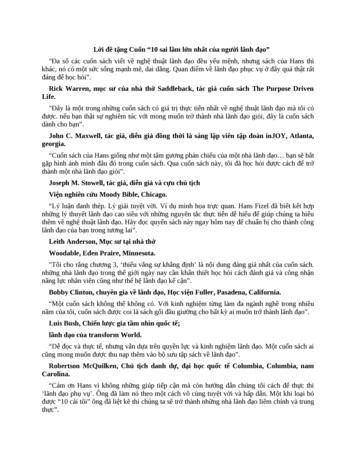
Chapter One: IntroductionSeismic exploration is widely used in the petroleum industry for hydrocarbondiscovery. The ultimate goal of seismic exploration is to image and interpret subsurfacestructures—the results of which depend on seismic data processed with tried and testedtechniques. Seismic data processing is one of the major steps in the exploration process,alongside the acquisition and interpretation of seismic data.1.1 Basic concepts of seismologyThis section is devoted to basic concepts used in exploration seismology, especiallythose used in this thesis.Seismic data are acquired in the field by many pairs of sources and receivers.Signals generated by a source located on the surface propagate into the earth and will bereflected back to the surface after it hits a subsurface interface. Receivers on the surfacewill record the reflected signals. A few basic concepts are reviewed as follows.Common mid-point (CMP) gatherA common mid-point (CMP) gather is defined as the data collection of traces thatshare the same mid-point position. A midpoint is the middle point between a source andreceiver pair. An example of the geometry of a CMP gather is shown in Figure 1.1. Forthe three pairs of source points and receivers, they have the same midpoint M on thesurface. The point D is the midpoint on the reflector and is also called the mid-depthpoint, which is also shared by the three pairs of sources and receivers.The variable offset, the distance between each source and receiver pair, is one ofthe two dimensions of CMP gathers. The other dimension is time, which is the traveltime1
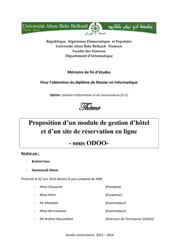
that the signal spends on the travel path from its source point to reflector and then toreceiver.The common depth point (CDP) gather is the same as a CMP gather for a singlehorizontal interface. But they are not the same for dipping interfaces. A CMP gather isone of the most frequently used concepts in this thesis.OffsetGroup intervalAirMSubsurfaceD- Source- ReceiverFigure 1.1 Geometry of a common mid-point (CMP) gather.Normal moveout (NMO) correctionIf the model in Figure 1.1 is a constant velocity model, the traveltime t ( x ) of aCMP gather along the raypath from a source to D then back to the associated surfacereceiver is defined as (Figure 1.2):t 2 ( x ) t 02 x 2 v 2 ,(1.1.1)where x is offset, the distance between the source and the associated receiver, v is thevelocity of the medium above the reflector, and t 0 is the two-way vertical traveltimealong MD or the two-way zero offset traveltime. For a flat reflector as introduced inFigure 1.1, Equation (1.1.1) describes a hyperbola with its apex at the zero offset trace in2
the two-way time-versus-offset plane (Yilmaz, 1987). A CMP gather illustrated in Figure1.3 shows the hyperbolic event associated with the model in Figure 1.1 and Equation(1.1.1). The difference between the two-way traveltime t(x) at offset x and the zero-offsettime t0 is called the normal moveout or NMO (Figure 1.3), which can be defined by thefollowing equation: t NMO t ( x ) t0 .x/2t/2(1.1.2)x/2t0 / 2t/2v constantFigure 1.2 The sketch of the traveltime associated with Figure 1.1.The process of NMO correction aims to remove the moveout effect on traveltimealong the offset dimension. The ideal result of NMO correction of Figure 1.3 is shown inFigure 1.4. However, in practice, the wavelet will be distorted and stretched after NMOcorrection.Normal moveout is a very basic and important seismology concept. The Radontransform, which is the main topic of this thesis and will be discussed later, has a verystrong relationship with this concept.3
xt0 tNMOt(x)Figure 1.3 A single-side CMP gather associated with the geometry in Figure 1.1.t(x) (s)x (m)Figure 1.4 The ideal result of NMO correction in Figure 1.3.4
CMP stackThe CMP stacking technique is proposed by Mayne (1962). It is a process ofgathering the data from NMO-corrected CMP gathers and summing them over offsets.The primary associated signals are enhanced by integration over offsets while randomnoise attenuated since primaries are flat on NMO-corrected gathers. Therefore, thesignal-to-noise ratio is improved after the CMP stacking technique is applied.Root Mean Square (RMS) velocityIn the case of a horizontal layered earth model as shown in Figure 1.5, the NMOvelocity in Equation (1.1.1) is replaced by the Root Mean Square (RMS) velocity:2,t 2 ( x ) t 02 x 2 v rms(1.1.3)where the RMS velocity v rms is defined by the Dix equation (Dix, 1955) as given by:v rms N τk 1kv k2N τk 1k,where vk is the interval velocity of the kth layer in the model, τ k is the verticaltraveltime in the kth layer and N is the total number of layers above t0 .5(1.1.4)
SGM τ1v1v2 τ2 τkvk τNvNDFigure 1.5 A horizontal layered earth model.1.2 Historical background to multiple reflectionsSeismic data are acquired by using energy sources to generate elastic waveswhich are reflected back to receivers on the surface by subsurface structures. An exampleof a simple seismic data acquisition geometry, with one source and a pair of receivers isshown in Figure 1.6. Primary reflections are those reflected only once at a certainsubsurface interface before they arrive at the receivers. These primary reflections provideus with useful information such as velocities and subsurface structural identification.Seismic imaging techniques are developed based on primary reflections.6
AirSRRSubsurfaceS - SourceR - ReceiverFigure 1.6 Seismic data acquisition geometry and primary reflections.However, in addition to primary reflections, receivers also pick up multiplereflections, which have been reflected between subsurface reflectors or the surface morethan once before being received on the surface. Multiple reflections often destructivelyinterfere with primary reflections and lead to poor seismic images. The removing ofmultiples from reflection seismograms has been a longstanding problem in explorationgeophysics. Multiple reflections yield dramatic effects especially on marine seismicsurveys. Because of the extremely high impedance contrast between the water surfaceand the air, the reflection coefficient of the water-air surface is close to -1. If the waterbottom is solid, the water layer can trap energy between the water surface and waterbottom. In this case, multiple reflections can be much stronger than primary reflections.Energy trap-related multiples include water-column reverberations (Figure 1.7) and pegleg multiples (Figure 1.8). Another major type of multiple is an interbed multiple, shownin Figure 1.9, which can happen, for example, in environments with salt.7
AirWaterSubsurfaceFigure 1.7 Water-column reverberations.AirWaterReflectorFigure 1.8 Peg-leg multiples.AirWaterReflectorFigure 1.9 Interbed multiples.8
1.3 Review of typical solutions to multiple attenuationBefore the seismic exploration industry employed the common midpoint (CMP)or common depth point (CDP) stacking techniques, multiple identification was used tohelp interpret and recognize primaries (Ellsworth, 1948). The main characteristics ofmultiple reflections include: (1) traveltime; (2) normal moveout; (3) periodicity of events;and (4) moveout of dipping reflectors. Backus (1959) may have been the first person toattempt to attenuate water reverberations using an inverse filter—the basis of predictivedeconvolution—using the reverberations’ periodic characteristic. The theory of predictivedeconvolution itself was proposed by Peacock and Treitel (1969).The fact that multiples and primaries exhibit different moveout traveltimes is thetheoretical underpinning of many other multiple-attenuation techniques, such as the CMPstacking technique, the f-k filter and the Radon transform. Mayne (1962) proposedmultiple suppression using CMP or CDP stacking techniques based on velocitydifferences between primaries and multiples. Typically a primary has less moveout than amultiple. If NMO correction is applied using the primary velocities, then the primaries onthe collected CMP gathers tend to be flat and aligned with each other while the multiplesare undercorrected and attenuated when they are stacked (Mayne, 1962 and Yilmaz,2001). This is considered to be the most robust and effective way to suppress multiplesand random noise (Foster and Mosher, 1992).The dipping information of events is preserved when they are mapped into the f-kdomain using the 2-D Fourier transform. If a CMP gather is moveout-corrected using avelocity mid-way between the primary and the multiple velocities, the primary reflectionwill be over-corrected and the multiple reflection under-corrected, meaning that they will9
appear in different quadrants in the f-k domain and thereby most of the energies areseparated from each other (Yilmaz, 1987 and 2001).The Karhunen-Loeve (K-L) transform, which optimally extracts coherent multipleinformation from multichannel input data, uses the moveout difference between multiplesand primaries to attenuate multiples in seismic data processing when CMP gathers arecorrected using the multiple velocities (Hemon and Mace, 1978; Jones, 1985; Jones andLevy, 1987).1.4 The Radon transformThe Radon transform is a mathematical technique that has been widely used inseismic data processing and image analysis. Three types of Radon transforms have beenused as multiple-attenuation techniques in seismic data processing: the slant-stack or τ-ptransform; the hyperbolic Radon transform; and the parabolic Radon transform (Trad,2001). The slant-stack transform can be combined with predictive deconvolution toattenuate multiples in the prestack seismic data based on the periodic characteristic ofmultiples, which is discussed in Chapter 2. In contrast to the slant-stack transform, thehyperbolic and parabolic Radon transforms are applied to multiple attenuation based onmoveout discrimination between multiples and primaries. In this thesis, I will focus moreon analyzing these two types of the Radon transform.The Radon transform was first established by Johan Radon (1917). Deans (1983)discusses the mathematical theory, and Durrani and Bisset (1984) examine thefundamental properties of the Radon transform. Thorson and Claerbout (1985) utilizedthe hyperbolic Radon transform as a velocity analysis tool, and the parabolic Radontransform was applied for the first time as a multiple attenuation technique by Hampson10
(1986). Since then, Radon transforms have become one of the most widely usedapproaches in attenuating multiples (for example Bradshaw and Ng, 1987; Kelamis et al.,1990; Kostov, 1990; Foster and Mosher, 1992; Hugonnet and Canadas, 1995; Sacchi andUlrych, 1995; Cary, 1998; Sacchi and Porsani, 1999; Trad, 2001; Oppert, 2002; Trad etal., 2002 and 2003; Ng and Perz, 2004).However, the resolution of Radon transforms has always been a serious problemfor geophysicists: investigators have been trying to enhance the focusing
Different approaches have been investigated and applied to the multiple attenuation problem, including the Radon transform which is an industry standard and has been attracting a lot of attention in the last two decades. In this thesis, Radon transform techniques are reviewed and analyzed and a new Radon algorithm, the