Transcription
EE302 Lesson 13:Antenna FundamentalsAntennas An antenna is a device that provides a transitionbetween guided electromagnetic waves in wires andelectromagnetic waves in free space.1
Reciprocity Antennas can usually handle this transition in bothdirections (transmitting and receiving EM waves). Thisproperty is called reciprocity.Antenna physical characteristics The antenna’s size and shape largely determines thefrequencies it can handle and how it radiateselectromagnetic waves.2
Antenna polarization The polarization of an antenna refers to the orientation ofthe electric field it produces.Polarization is important because the receiving antennashould have the same polarization as the transmittingantenna to maximize received power.Antenna polarization Horizontal PolarizationVertical PolarizationCircular Polarization Electricand magnetic field rotate at the frequencyof the transmitter Used when the orientation of the receivingantenna is unknown Will work for both vertical and horizontal antennas RightHand Circular Polarization (RHCP) Left Hand Circular Polarization (LHCP) Both antennas must be the same orientation (RHCP orLHCP)3
Wavelength ( ) You may recall from physics that wavelength ( ) andfrequency (f ) of an electromagnetic wave in free spaceare related by the speed of light (c)c f or cfTherefore, if a radio station is broadcasting at afrequency of 100 MHz, the wavelength of its signal isgivenc3.0 108 m/s 3m f 100 106 cycle/sWavelength and antennas The dimensions of an antenna are usually expressed interms of wavelength ( ).Low frequencies imply long wavelengths, hence lowfrequency antennas are very large.High frequencies imply short wavelengths, hence highfrequency antennas are usually small.4
ANTENNASAs much an art as it is a science.Everyone’s Dream Car5
What to look for in Antennas Freq/WavelengthBeam PatternBandwidthGainBasic Antenna An antenna can be a length of wire, a metal rod,or a piece of metal tubing.Antennas radiate most effectively when theirlength is directly related to the wavelength of thetransmitted signal.Most antennas have a length that is somefraction of a wavelength.One-half and one-quarter wavelengths are mostcommon.6
Basic Antenna Let’s start by looking at the radiation pattern of anisotropic point source.Power from an isotropic point source isequally distributed in all directionsIt is completely unfocused.Isotropic Point SourceRadiation Pattern for Isotropic PointSourceAntenna radiates equallyin all directionsAntenna only existstheoretically7
Antenna gain (G)Because an antenna is a passive device, the power radiated cannot be greater than the input power.The ability of an antenna to focus electro-magnetic energy isdefined by its gain.Antenna gain is expressed as a ratio of the effective radiatedoutput power (Pout) to the input power (Pin)The gain of an antenna is a measure of power transmitted relativeto that transmitted by an isotropic source. Antenna gain relative to an isotropic source is expressed indecibels as dBi. Effective Radiated Power The effective radiated power (ERP or EIRP) is thegain of an antenna (with respect to an isotropicradiator) multiplied by its input power.ERP input power antenna gain For example, a highly directional antenna with a gain of7 has an input power of 1-kW. Its ERP is therefore 7kW.8
Measuring Antenna Radiation PatternsAntenna is rotated in an AnechoicChamber to measure radiationpatternRadiation pattern of any antennaIs the shape of theElectro-magnetic field radiated orReceived by the antennaDipole Antenna One of the most widely used antenna types isthe half-wave dipole.The half-wave dipole, also called a doublet, isformally known as the Hertz antenna.A dipole antenna is two pieces of wire, rod, ortubing that are one-quarter wavelength longat the operating resonant frequency.9
Electric and Magnetic Fields around aTransmission LineUse the right hand ruleElectric and magneticfield lines around a conductorBetween the conductor, magnetic field lines add.Beyond the conductor, the field lines cancel each otherConverting a Transmission Line into anAntennaInefficient radiation10
Converting a Transmission Line intoan AntennaBending at right anglesproduces anefficient radiatorMagnetic fields now support each otherOptimum radiation occurswhen the length is1/2 of a wavelengthThe Dipole AntennaFig. 14-1011
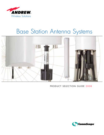
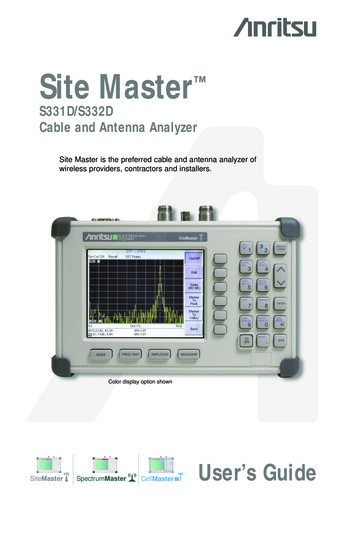
Three-dimensional radiation pattern for a dipole.Dipole AntennaVertically MountedThis pattern is a donut shape withthe antenna passing thru the center.There is no radiation from the end of the antenna.Dipole Radiation PatternAntenna Axis12
Antenna LossesRadiation Loss Causedby radiation resistance Results in radiated RF energyResistive Loss Resultsin heat due to resistance of conductorBy Definition The dipole has an impedance of 73 Ω at its center, which is theradiation resistance. An antenna ideally appears as a resistor to the transmitter. This“radiation resistance” does not dissipate power in the form of heat;the power is dissipated as radiated electromagnetic energy.An antenna is a frequency-sensitive device, and a particular antennacan be operated over a range of frequencies (BW).At the resonant frequency, the antenna appears to be a pureresistance of 73 ΩEquivalent circuitof a dipole13
Antenna gain (G) A dipole antenna gain is 1.6410log10 (1.64) 2.15 dBi A half-wave dipole antenna has a power gain of 1.64(or 2.15 dB) over an isotropic source.Antenna gain relative to a dipole antenna can beexpressed in decibels as dBd.Thus, an antenna with a gain of 3 dBd would have again of 5.15 dBi (3 dB 2.15 dB)Actual Antenna Lengths A dipole resonates best when it is approx. 95% of theactual “half-wavelength length”Shortcut:Lfeet 468/f MHz (This is in Feet)1 ft .3048 mDipole hung vertically is closest to an isotropicradiatorBottom of dipole antenna should be at least ½ awavelength off the ground May make total structure height unreasonable14
Example How long would a dipole antenna be for AM1100? Calculateusing wavelength and shortcutEffect of Antenna Length onRadiation Pattern1λ Dipole1.5λ DipoleWe will look at this more later.15
Conical Antenna A common way to increase bandwidth is to use aversion of the dipole antenna known as the conicalantenna.The center radiation resistance of a conical antennais much higher than the 73 Ω usually found whenstraight-wire or tubing conductors are used.The primary advantage of conical antennas is theirtremendous bandwidth.They can maintain a constant impedance and gainover a 4:1 frequency range.Conical Antenna and VariationConical(expensive)Bow-tie(flat)grid, or flat plateTwo-dimensional cone,Equally effectiveFig. 14-1416
Antenna Beam WidthDipole ishorizontally orientedMarconi or Ground-Plane VerticalAntenna The quarter-wavelength verticalantenna, also called a Marconiantenna is widely used.It is similar in operation to a verticallymounted dipole antenna.The Marconi antenna is half the lengthof a dipole antenna.Fig. 14-20a The earth acts as a type of electrical “mirror,” effectivelyproviding the other quarter wavelength making it equivalentto a vertical dipole.17
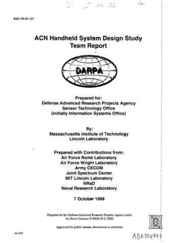
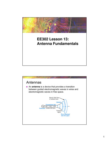
Figure 12–6A Marconi antennaCopyright 2006 by Pearson Education, Inc.Upper Saddle River, New Jersey 07458All rights reserved.Tom WheelerElectronic Communications for Technicians, 2eMonopole Radiation PatternGround plane reflectionslift pattern upMonopole showing effects of ground plane18
Advantages Half the length of a dipoleCan be located at earth level without degradingperformanceHas omni-directional radiation pattern similar todipoleDisadvantages Gain is slightly lower than a dipole (about 1 dBless), but for our purposes we will consider themthe sameAntenna is extremely dependent on conductivityof the earthUsing a counterpoise will improve conductivity19
Counterpoise Sometimes connecting a monopole antenna to theground is not feasible. Create a ground. Antennas mounted on buildings or towersSoil is highly resistive (dry)Counterpoise A counterpoise is a flatstructure of wire or screenthat forms an artificialreflecting surface for themonopole antenna if theactual earth cannot be used.20
Counterpoise Counterpoise requirementsMust be at least equal to or largerthan the antenna. Should extend in equal distancesfrom the antenna. Must be insulated from theground. The performance of a quarterwave antenna (either wellgrounded or using acounterpoise) is essentially thesame as a half-wave dipoleantenna.Counterpoise21
Adjusting Antenna Impedance“Drooping” radials is one way to adjust antenna impedance22
8 Antenna gain (G) Because an antenna is a passive device, the power radiated can not be greater than the input power. The ability of an antenna to focus electro-magnetic energy is defined by its gain. Antenna gain is expressed as a ra tio of the effective radiated output power (Pout) to the input power (Pin) The gain of an antenna is a measure of power transmitted relative