Transcription
Cisco Dual LTE-Single GPS Multi-band AntennaInstallation GuideThis document provides the description, supported features, and installation instructions of the CiscoDual LTE-Single GPS Multi-band (4G-LTE-ANTM-O-3) Antennas.CautionRead the information in Safety Precautions before installing or replacing antennas.This document contains the following sections: Overview of the 4G-LTE-ANTM-O-3 Antenna, page 1 Supported Antennas, page 12 Supported Antenna Accessories, page 12 Antenna Options by Deployment Type, page 13 Safety Precautions, page 13 Installation Instructions, page 15 Deployment Scenarios, page 17 Antenna Ports, page 19 Related Documentation, page 20 Obtaining Documentation and Submitting a Service Request, page 20Overview of the 4G-LTE-ANTM-O-3 AntennaDeciding which antenna to use involves multiple factors, such as coverage area, maximum distance,indoor location, outdoor location, and antenna height.When an antenna is used indoors, the building construction, ceiling height, and internal obstructionsmust be considered. In outdoor environments, obstructions such as trees, vehicles, buildings, and hillsmust be considered. Distance is the primary factor when using outdoor-wireless communications.However, coverage area also becomes important when you use wireless client devices to communicatewith a wireless device.Cisco Systems, Inc.www.cisco.com
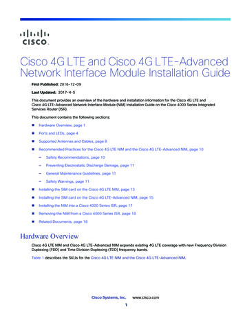
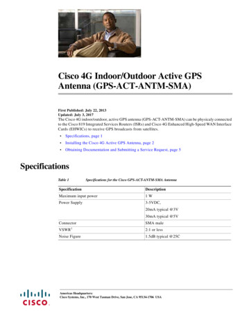
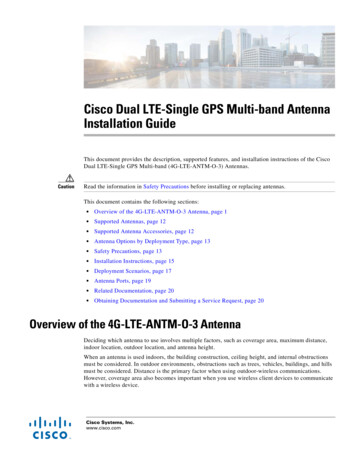
Overview of the 4G-LTE-ANTM-O-3 Antenna4G-LTE-ANTM-O-3 antenna is an integrated 3-in-1- indoor and outdoor antenna. It comes with twoLong Term Evolution (LTE) antennas and one Global Positioning System (GPS) antenna in a singleradome. Figure 1 shows the 4G-LTE-ANTM-O-3 antenna.Figure 14G-LTE-ANTM-O-3 AntennaParts ListThe shipment of your antenna includes the following items: One Antenna Unit Two SMA-Female to TNC-Male Adapters Installation GuideFeatures of the 4G-LTE-ANTM-O-3 AntennaThe 4G-LTE-ANTM-O-3 antenna supports the following features: No tune, multiband coverage, dual 4G LTE, and GPS L1 frequencies. Metal 5/8-inch stud mount with serrated face nut provides single cable exit for easier installation orantenna replacement. Attractive low-profile housing for added overhead clearance. IP67-compliant design provides maximum protection against water or dust under severeenvironmental conditions. High-performance, low-loss cable, and high-quality connectors for maximum Radio Frequency(RF) system efficiency. UV-resistant red, blue, black, or white radome.Cisco Dual LTE-Single GPS Multi-band Antenna Installation Guide2OL-32387-01
Overview of the 4G-LTE-ANTM-O-3 AntennaTechnical SpecificationsTable 1 lists the specifications for the RF antenna.Table 1Specifications of RF antennaOperating Frequencies698-960 MHz1710-2700 MHzPolarizationVertical, linearNominal Impedance50 Ohms1Gain (Typical)2.5 dBiMaximum Power3 WattsVSWR2 2.5:1Elevation Plane (3 dB Beamwidth)30 (nominal)Azimuth Plane (3 dB Beamwidth)Omni-directionalConnector typeSMA-MaleCable4 ft RG174 VW-1 compliantHeight90 mmBase Diameter137 mmColorWhite, Black, Red or BlueFlammabilityUL-94 V0EnvironmentIndoor and outdoorMounting5/8 inch lug with serrated face nut, optionaladhesive backing (peel-off), 17 sq. inches area(minimum) on a flat smooth surface, 5/8 inchdiameter hole through mounting surfaceOperating and storage temperatureIngress Protection-40 to 85 degree C3IP671. Total gain, free space test when mounted on a 1-foot diameter ground plane with unused ports loaded.2. Free space Voltage Standing Wave Ratio (VSWR) over all operating frequency ranges when mounted on a 1-footdiameter ground plane with unused ports loaded.3. When mounted per installation instructions.Cisco Dual LTE-Single GPS Multi-band Antenna Installation GuideOL-32387-013
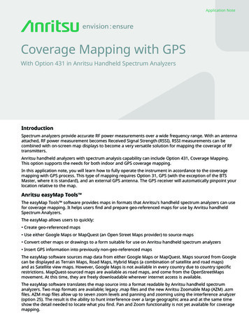
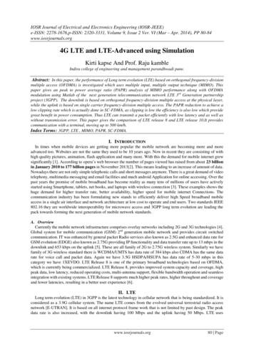
Overview of the 4G-LTE-ANTM-O-3 AntennaTable 2 lists the specifications for the GPS Antenna.Table 2Specifications of the GPS AntennaFrequency Band1575.42 MHz (GPS L1)Amplifier Gain26 dBc 3 dBNominal Impedance50 OhmsOutput VSWR1.5:1 typicalDC Current20 mA nominal; 30 mA @ -40 C to 85 CDC Voltage3.3-5 VNoise Figure1.8 dB typicalFiltering 40 dB rejection @ 50 MHz from centerfrequencyFigure 2 shows the parts of 4G-LTE-ANTM-O-3 Antenna.Figure 2Parts of 4G-LTE-ANTM-O-3 Antenna213372740451GPS and 2 LTE antennas inside42Radome available in 4 colors: White, Black, 5Red or Blue (Indoor or Outdoor)3GasketMounting studCablesCisco Dual LTE-Single GPS Multi-band Antenna Installation Guide4OL-32387-01
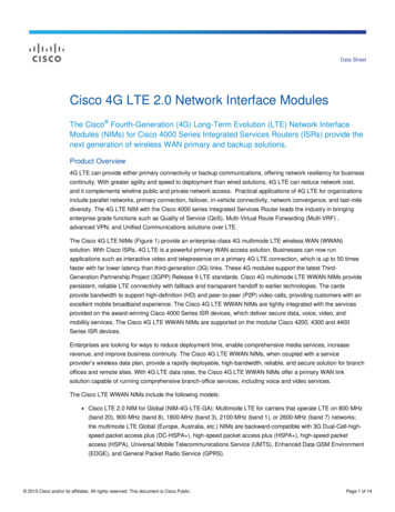
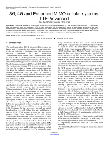
Overview of the 4G-LTE-ANTM-O-3 AntennaFigure 3 shows the antenna with cable labels.1LTE372914GPS3LTE2The Antenna with Cable LabelsMPN07-01329-01Figure 31MPN LABEL3GPS ID LABEL2LTE-ID LABEL 2EACisco Dual LTE-Single GPS Multi-band Antenna Installation GuideOL-32387-015
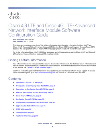
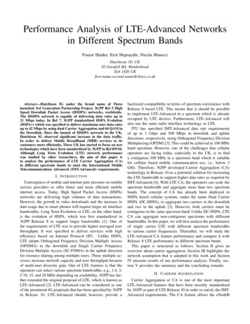
Overview of the 4G-LTE-ANTM-O-3 AntennaFigure 4 shows the Low Band 698-960 MHz EL (PHI 0).Low band 698-960 MHz EL (PHI 0)372742Figure 4Cisco Dual LTE-Single GPS Multi-band Antenna Installation Guide6OL-32387-01
Overview of the 4G-LTE-ANTM-O-3 AntennaFigure 5 shows the Low Band 698-960MHz EL (PHI 90).Low band 698-960MHz EL (PHI 90)372743Figure 5Cisco Dual LTE-Single GPS Multi-band Antenna Installation GuideOL-32387-017
Overview of the 4G-LTE-ANTM-O-3 AntennaFigure 6 shows the Low Band 698-960MHz AZ (THETA 90).Low Band 698-960MHz AZ (THETA 90)372744Figure 6Cisco Dual LTE-Single GPS Multi-band Antenna Installation Guide8OL-32387-01
Overview of the 4G-LTE-ANTM-O-3 AntennaFigure 7 shows High Band 1710-2700MHz EL (PHI 0).High Band 1710-2700MHz EL (PHI 0)372745Figure 7Cisco Dual LTE-Single GPS Multi-band Antenna Installation GuideOL-32387-019
Overview of the 4G-LTE-ANTM-O-3 AntennaFigure 8 shows High Band 1710-2700MHz EL (PHI 90).High Band 1710-2700MHz EL (PHI 90)373009Figure 8Cisco Dual LTE-Single GPS Multi-band Antenna Installation Guide10OL-32387-01
Overview of the 4G-LTE-ANTM-O-3 AntennaFigure 9 shows High Band 1710-2700MHz AZ (THETA 90).High Band 1710-2700MHz AZ (THETA 90)373010Figure 9Cisco Dual LTE-Single GPS Multi-band Antenna Installation GuideOL-32387-0111
Supported AntennasSupported AntennasTable 3 lists the supported antennas.Table 3Supported AntennasPart NumberDescription4G-LTE-ANTM-O-3-WIndoor or outdoor low-profile antenna with 4-footdongle, white radome.4G-LTE-ANTM-O-3-BIndoor or outdoor low-profile antenna with 4-footdongle, black radome.4G-LTE-ANTM-O-3-RIndoor or outdoor low-profile antenna with 4-footdongle, red radome.4G-LTE-ANTM-O-3-CIndoor or outdoor low-profile antenna with 4-footdongle, blue radome.Supported Antenna AccessoriesTable 4 lists the supported antenna accessories.Table 4Supported Antenna AccessoriesPart NumberCable LengthMaximum Insertion Loss4G-CAB-LMR240-2525 ft (7.5 m)2.1 dB @ 700 MHz4.0 dB @ 2.6 GHz4G-CAB-LMR240-5050 ft (15 m)4.1 dB @ 700 MHz7.4 dB @ 2.6 GHz4G-CAB-LMR240-7575 ft (23 m)6.1 dB @ 700 MHz11.0 dB @ 2.6 GHz4G-CAB-ULL-2020 ft (6 m)0.90 dB @ 700 MHz1.8 dB @ 2.6 GHz4G-CAB-ULL-5050 ft (15 m)2.2 dB @ 700 MHz4.3 dB @ 2.6 GHzCisco Dual LTE-Single GPS Multi-band Antenna Installation Guide12OL-32387-01
Antenna Options by Deployment TypeAntenna Options by Deployment TypeTable 5 lists the antenna options by deployment type.Table 5Antenna Options by Deployment TypeAntenna AccessoriesRequiredDeployment TypeDescriptionIndoorThe antenna is installed indoors on a Nonegrounded metal surface andattached directly to a router.Indoor, with extensionThe antenna is installed on agrounded metal surface andattached to a router with extensioncables.Outdoor flush 4G-CAB-LMR240-25 4G-CAB-LMR240-50 4G-CAB-LMR240-75 4G-CAB-ULL-20 4G-CAB-ULL-50The antenna is installed outdoors to Nonea grounded metal surface andattached directly to a routermounted indoors.Safety PrecautionsThis section contains the following warning statements. A warning means danger. You are in a situationthat could cause bodily injury. Before working on an equipment, be aware of the hazards involved withelectrical circuitry and standard safety practices to prevent accidents.Statement 1052—Installing and Grounding the AntennaWarningDo not locate the outdoor antenna near overhead power lines or other electric light or power circuits,or where it can come into contact with such circuits. When installing the antenna, take extreme carenot to come into contact with such circuits, as they may cause serious injury or death. For properinstallation and grounding of the antenna, refer to national and local codes (for example, U.S.:NFPA70, National Electrical Code, Article 810, Canada:Canadian Electrical Code, Section 54).Statement 1024—Ground ConductorWarningThis equipment must be grounded. Never defeat the ground conductor or operate the equipment in theabsence of a suitably installed ground conductor. Contact the appropriate electrical inspectionauthority or an electrician if you are uncertain that suitable grounding is available.Cisco Dual LTE-Single GPS Multi-band Antenna Installation GuideOL-32387-0113
Safety PrecautionsStatement 1025—Use Copper Conductors OnlyWarningUse copper conductors only.Statement 1046—Installing or Replacing the UnitWarningWhen installing or replacing the unit, the ground connection must always be made first anddisconnected last.CautionFor your physical safety, and to help you install your antenna successfully, follow these safetyprecautions. If you are installing an antenna for the first time, for your own safety as well as others, seekprofessional assistance. Your Cisco sales representative can explain which mounting method to usefor the size and type of antenna you are about to install. Before you install an antenna, contact your Cisco account representative to explain which mountingmethod to use for the size and type of antenna that you are about to install. Find someone to help you—installing an antenna is often a two-person job. Select your installation site with safety, as well as performance, in mind. Remember that electricpower lines and phone lines look alike. For your safety, assume that any overhead line can kill you. Contact your electric power company. Tell them your plans and ask them to come and look at yourproposed installation. Plan your installation carefully and completely before you begin. Each person involved in aninstallation should be assigned to a specific task, and should know what to do and when to do it. Oneperson should be in charge of the operation to issue instructions and watch for signs of trouble. When installing your antenna, follow these guidelines:– Do not use a metal ladder.– Do not work on a wet or windy day.– Do dress properly—wear shoes with rubber soles and heels, rubber gloves, and a long-sleevedshirt or jacket. If the assembly starts to drop, move away from it and let it fall. Because the antenna, mast, cable,and metal guy wires are all excellent conductors of electrical current, even the slightest touch of anyof these parts to a power line completes an electrical path through the antenna and the installer. If any part of the antenna system should come in contact with a power line, do not touch it or try toremove it yourself. Call your local power company to have it removed safely. If an accident should occur with the power lines, call for qualified emergency help immediately.Cisco Dual LTE-Single GPS Multi-band Antenna Installation Guide14OL-32387-01
Installation InstructionsInstallation InstructionsThe following section contains steps for installing the 4G-LTE-ANTM-O-3 antenna:Step 1Step 2NoteWhile choosing the location, keep the following in mind: Attempt to center the antenna on a flat plane. Attempt to position the antenna so that it has 8 inches of flat plane in any given direction. Attempt to space at least 16 inches from an adjacent antenna or metallic structure and choose alocation with gentle surface curves to ensure proper sealing. Ensure that there is a space that is 2 inches deep and 2 inches in diameter below the mounting surfaceto allow sufficient clearance for the mounting stud, hardware, and cables. Ensure that the diameter of the hole is 5/8 inch.Drill a hole through the mounting surface where the center of the antenna is located, as shown inFigure 10.Ensure that the hole is deburred of sharp edges to prevent cable damage during installation.Drill the Mounting Surface372748Figure 10Step 3Clean the mounting surface around the hole. The surface must be free of any debris, which wouldotherwise prevent the antenna's inner foam gasket from adhering to or the outer rubber gasket fromforming a seal.Step 4Remove the nut from the mounting stud and cables one by one.Step 5Insert the mounting stud through the hole and then thread the cables through the serrated face nut oneby one.NoteIt is important that the orientation of the serrated face nut should be correct. Otherwise, the serrated partof the lock nut will not bite into the mounting stud.Cisco Dual LTE-Single GPS Multi-band Antenna Installation GuideOL-32387-0115
Installation InstructionsFigure 11 shows the bottom view of the antenna.Figure 11Bottom View of the Antenna4G-LTE-ANTM-O-3-B4G LTE 3 in 1 outdoor Blackantenna 700MHZwww.cisco.com/go/4g1SN: 143008813INSTALLATIONTORQUE 4.5Nm210MPN: 07-01329-01RoHsComplaint372915Made in: CNStep 61Product ID and Serialization Label3Liner2MPN and Torque LabelPosition the antenna onto the mounting surface and tighten the nut hand-tight, as shown in Figure 12.Tighten it further using a wrench until the antenna is fully seated. Visually inspect the outer rubberantenna gasket to ensure that it has been compressed and sealed tightly against the mounting surface andradome.Tighten the Nut after the Antenna is fully seated372753Figure 12Cisco Dual LTE-Single GPS Multi-band Antenna Installation Guide16OL-32387-01
Deployment ScenariosDeployment ScenariosFigure 13 shows the deployment of the 4G-LTE-ANTM-O-3 antenna on an ATM with a single router.NoteAll the three antenna cables are SubMiniature version A (SMA-male) connectors, but the MAIN and theDiversity (DIV) of the router has the Threaded Neill–Concelman (TNC-female) connectors, and the GPShas an SMA-female connector. In this case, an SMA-female to TNC-male adapter needs to be used toconnect the SMA-male connectors to the MAIN and DIV of the router because they cannot be connectedto the SMA-male connectors directly.Figure 13Deployment of an Antenna with One RouterRouterSIMMODEMMAINDIV 5VPowerAdapterAC or DC inputoption available372746GPSCisco Dual LTE-Single GPS Multi-band Antenna Installation GuideOL-32387-0117
Deployment ScenariosFigure 14 shows the deployment of 4G-LTE-ANTM-O-3 on an ATM with dual routers.Figure 14Deployment of an Antenna with Dual RoutersSIMMODEMRouter AMAINDIVGPSRF SplitterPowerAdapter 5VSIMMODEMMAINDIVRouter BRF Splitter 5VPowerAdapterAC or DCpower adaptersare available372747GPSCisco Dual LTE-Single GPS Multi-band Antenna Installation Guide18OL-32387-01
Antenna PortsAntenna PortsThis section describes the antenna ports, their locations on the router, and the recommendedantenna-installation locations. You can connect an antenna to the ports of a Cisco Enhanced High-SpeedWAN Interface Card (EHWIC) or Cisco 819 series router.Connecting the Antenna to the Cisco 819 Series Router or Cisco EHWICThe antenna ports are shown in Figure 15, and the front panel details of the Cisco 819 series router areshown in Figure 16.Figure 15Insert Base of Antenna into Router Antenna OLTEGPS567372961GPS81Mounting 8Antenna Connectors—M1/DIV, M0/MAIN4RSVD (reserved) port, USB 2.0 mini type B 95LED—EVDO3Antenna Connector—GPS1. GPS Global Positioning System.2. RSSI Received Signal Strength Indicator.3. EVDO Evolution-Data Optimized.Cisco Dual LTE-Single GPS Multi-band Antenna Installation GuideOL-32387-0119
Related DocumentationFigure 16Front Panel Details of Cisco 819 4G LTE ISR8122854475123467910 111314G Antenna connector—M0/MAIN8GE WAN port2LEDs9Antenna Connector—GPS Console/Aux port3Reset button10 Power input44G/3G port11 Power switch54G Antenna connector—M1/DIV12 Active GPS antenna connector6Serial port13 Ground7FE portRelated Documentation For information about antennas and modules, see:www.cisco.com/go/cg-modules For information about omnidirectional and directional antennas, chnologies tech note09186a00807f34d3.shtmlObtaining Documentation and Submitting a Service RequestFor information on obtaining documentation, submitting a service request, and gathering additionalinformation, see the monthly What’s New in Cisco Product Documentation, which also lists all new andrevised Cisco technical documentation, w/whatsnew.htmlSubscribe to the What’s New in Cisco Product Documentation as a Really Simple Syndication (RSS)feed and set content to be delivered directly to your desktop using a reader application. The RSS feedsare a free service and Cisco currently supports RSS version 2.0.This document is to be used in conjunction with the documents listed in the “Related Documentation”section.Cisco and the Cisco logo are trademarks or registered trademarks of Cisco and/or its affiliates in the U.S. and other countries. To view a list ofCisco trademarks, go to this URL: www.cisco.com/go/trademarks. Third-party trademarks mentioned are the property of their respective owners.The use of the word partner does not imply a partnership relationship between Cisco and any other company. (1110R)@2014 Cisco Systems, Inc. All rights reserved.Cisco Dual LTE-Single GPS Multi-band Antenna Installation Guide20OL-32387-01
Overview of the 4G-LTE-ANTM-O-3 Antenna Table 2 lists the specifications for the GPS Antenna. Figure 2 shows the parts of 4G-LTE-ANTM-O-3 Antenna. Figure 2 Parts of 4G-LTE-ANTM-O-3 Antenna Table 2 Specifications of the GPS Antenna Frequency Band 1575.42 MHz (GPS L1) Amplifier Gain 26 dBc 3 dB Nominal Impedance 50 Ohms Output VSWR 1.5:1 typical