Transcription
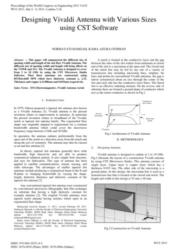
Proceedings of the World Congress on Engineering 2011 Vol IIWCE 2011, July 6 - 8, 2011, London, U.K.Designing Vivaldi Antenna with Various Sizesusing CST SoftwareNORHAYATI HAMZAH, KAMA AZURA OTHMANAbstract :- This paper will summarized the different size ofopening width and length of the slot flare Vivaldi Antenna. Thedifferent size of opening width and length will bring effects onthe VSWR and S11. The Vivaldi Antenna is designed to coverfrom 2 to 18 GHz by using the CST Microwave StudioSoftware. Then these antennas are constructed usingRT/Duroid 5870 which have dielectric constant r 2.33.Thickness and copper is 0.508mm and 0.035mm respectively.Index Terms - EM (Electromagnetic), Vivaldi Antenna AerialA notch is formed in the conductive layer and the gapbetween the sides of the slot widens from minimum at closedend of the slot to a maximum at the open end. The closed endof the notch line may be fed by any one of a variety oftransmission line including microstrip lines, stripline, finlines and probes.In conventional Vivaldi antennas, the gap ismirror symmetrical about an axis through the centre of theslot and each side has the conductive layer flares. The flaredslot is an effective radiating element. On the reverse side ofsubstrate there are formed a ground plane of conductor whichacts as the return conductor as shown in Fig.1.I. INTRODUCTIONIn 1979, Gibson proposed a tapered slot antenna also knownas a Vivaldi Antenna [1]. Vivaldi antenna is the presentinvention relates to improvement in antennas. In particularthe present invention relates to broadband of the Vivaldi,notch or tapered slot antenna family. The exponential flareshape was originally adapted to requirement for a constantbeamwidth antenna which could cover the microwavefrequency range between 2 GHz and 20 GHz.In operation, the antenna radiates preferentially from theopen end of the notch in a direction away from the notch andalong the axis of symmetry. The antenna may thus be classedas an end-fire antenna [2].In theory, tapered slot antennas generally have widebandwidth, high directivity and are able to producesymmetrical radiation pattern. It also simple feed structure,and easy for fabrication. This type of antenna has beenapplied to satellite communications, remote sensing, andradio telescope. The advantages of endfire tapered slotantennas include producing a symmetrical beam in the E-andH-plane or changing beamwitdh by varying the shape,length, dielectric thickness and dielectric constant of thetapered slot antenna [7].Fig.1 Architecture of Vivaldi AntennaII. METHODOLOGYA.Designing AntennaVivaldi antenna is designed to radiate at 2 to 18 GHz.Fig.2 illustrate the layout of a construction Vivaldi antennaby using CST Microwave Studio. This antenna consists ofsingle layer. Upper layer is copper layer which has athickness 0.035 mm. The other side of the microstrip is aground plane. In this design, the microstrip line is used as atransmission line that is located at the closed end notch. Thelength and width in this design is 55 mm x 40 mm.Any conventional tapered slot antenna were constructedby conventional microwave lithographic thin film techniqueon substrate that having a high dielectric constant forexample alumina [2]. The original Vivaldi antennas weretapered notch antenna having notches which open in anexponential flare shape.Manuscript received January 11, 2011; revised February 09, 2011.Norhayati Hamzah is with the Faculty of Electrical Engineering, UniversitiTeknologi MARA, 40450 Shah Alam, Selangor Darul Ehsan 350;norhayati3006@gmail.com).Kama Azura Othman is with the Faculty of Electrical Engineering,Universiti Teknologi MARA, 40450 Shah Alam, Selangor Darul EhsanMalaysia (phone: 6012-373-6499; fax: 603-554-43740; e-mail:azzuerra@gmail.com).ISBN: 978-988-19251-4-5ISSN: 2078-0958 (Print); ISSN: 2078-0966 (Online)Fig.2 Construction on Vivaldi AntennaWCE 2011
Proceedings of the World Congress on Engineering 2011 Vol IIWCE 2011, July 6 - 8, 2011, London, U.K.B.D.CalculationIn theory, the maximum opening width [7] is: 𝑔 c𝑓 min εrVNA (Vector Network Analyzer) TestThis technique is use to measure the value of SII andVSWR of the fabrication antenna. It can be use to comparethe simulated and the fabricated antenna. Fig.3 shows theVNA equipment.where,c speed of light (3 x 10⁸)f min frequency minimum (2G) r dielectric constant (2.33)Thus, g 3 10 82G 2.33 98.27 mmSo,W max g/2 98.27 mm / 2Fig.3 VNA testE. 49.13 mmThen, the minimum of opening width is:W min Cf εrAntenna Training System (ED-3200A)This technique consists of a transmitter and receiverantenna. It can be used to gain the radiation pattern of thereceiving antenna which is the Vivaldi antenna.where,f center frequency (10G)W min 3 10 810G 2.33 19.65 mmTherefore, six different sizes of opening width andlength have been developed. The characteristic for each sizeof antennas is described in Table 1.Fig.4 Measurement between Horn Antenna and VivaldiAntennaTable 1Size of opening width and length of antennaTypeType 1Type 2Type 3Type 4Type 5Type 6C.Opening width303035354040Opening length271727172717III.A.Simulation ResultsTable 2 shows the simulated results. From all theresults, type 3 shows the best performance. This is due totype 3 has a lower value of S11 as compared to otherdesigns. Furthermore, the value of VSWR for type 3 isapproximately to 1.Table 2Simulation resultCST Microwave StudioThese designs were simulated by using CST softwareto determine the characteristic of the designed antenna.Simulations were done to estimate the values of S11 andVSWR for all type of designs.ISBN: 978-988-19251-4-5ISSN: 2078-0958 (Print); ISSN: 2078-0966 (Online)RESULTTypesType 1Type 2Type 3Type 4Type 5Type .5011.0121.3791.1301.227WCE 2011
Proceedings of the World Congress on Engineering 2011 Vol IIWCE 2011, July 6 - 8, 2011, London, U.K.VSWR 1.01dBFig.5 The value of S11 for all 6 types designFig.8 Simulated VSWR for type 3Fig.6 The value of VSWR for all 6 types designFig.9 Farfiled pattern for type 3From the simulation result, it was found that theopening length will give effect on the VSWR. The longerthe length of the opening the lower value of VSWR can begenerated. The value of S11 gives better results if theopening length is longer. In conclusion, to gain the bestresult on S11 and VSWR the opening width and length mustbe in range between the ratios of 1 to 1.5. Next, byincreasing the opening width it will give effect on theradiation pattern.Fig.10 Radiation pattern for type 3Fig.6, 7, 8, and 9 are the results of type 3 design for S11,VSWR and radiation pattern. The directivity and gain of theantenna is 11.09dBi and 10.58dB respectively.S11 -44.25dBB.Fig.7 Simulated S11 for type 3ISBN: 978-988-19251-4-5ISSN: 2078-0958 (Print); ISSN: 2078-0966 (Online)Fabrication ResultAll six different types of Vivaldi antenna were done insimulation. Based on the result obtained from the simulationof antenna design of type 3 was chosen to be fabricatedsince it gives the most optimum specification.WCE 2011
Proceedings of the World Congress on Engineering 2011 Vol IIWCE 2011, July 6 - 8, 2011, London, U.K.Initially, the S11 and VSWR of a single Vivaldiantenna was measured by using VNA test. Referring toFig.6, the simulation shows that S11 value is -44.45dB. Butin practical experiment (Fig.11), the value is -25.64dB andthe center frequency was shifted from 10 GHz to 9.84 GHz.Similarly, the VSWR value showed that the simulated valuein Fig.7 is 1.0 at 10 GHz while the value from theexperiment is 1.11 in Fig. 12. The center frequency of theantenna of type 3 was shifted 1.6% from the 10 GHz.Fig.11 Fabricated antenna of type 3Lastly, the results obtain from both simulation andexperiment shows that most of the value attained were notexactly similar. This is due to the fact that most equipmenthas their setting errors. Also, the condition of surroundingmust be considered. Not to forget human error such assoldering and during fabrication. Furthermore, the frequencywas shifted from the 10 GHz to 9.84 GHz. It may be due tothe grounding effects.IV. CONCLUSIONFig.12 Experimental S11 of type 3 antennaIn this paper, the designs of Vivaldi antenna withvarious sizes were presented. The simulation and fabricationresult of 6 different sizes has been shown. Vivaldi antenna isa wideband antenna. The performance of the antenna meetsthe desired requirement in term of S11 and VSWR. Vivaldiantenna for 2 to 18 GHz is a wideband antenna producedgood directivity and high gain with the suitable openingwidth and opening length. Also, from the observation thedesign of the opening width and opening length affects thecharacteristic of antenna. The application of this antenna cansupport frequencies between 2 – 18 GHz which is used inradar and military equipment. It also can be applied tosatellite communication.In additional, this antenna can be improved by designing onantipodal Vivaldi antenna and balance antipodal Vivaldiantenna. It is because both of two antennas will become anultrawide-band antenna with increasing the S11.REFERENCESFig.13 Experimental VSWR of type 3 antenna[1] P. J. Gibson, ―The Vivaldi Aerial‖, Proc. 9th EuropeMicrowave. Conerence., 1979, pp. 101–105.[2] James Joseph Fisher, ―Vivaldi Antenna,‖ WorldIntellectual Property Organization, Aug.8,2006.[3]E. Gazit, ―Improved Design of the Vivaldi Antenna‖,Proc. Inst. Electr. Eng.—H, vol. 135, no. 2, pp. 89–92,Apr. 1988.[4] K. S. Yngvesson, D. H. Schaubert, T. L. Korzeniowski,E. L.Kollberg, T. Thungren, and J. Johansson, ―EndfireTapered Slot Antennas on Dielectric Substrates,‖ IEEETrans. Antennas Propag., vol. AP-33, no. 12, pp.1392–1400, Dec. 1985.Fig 14 Experimental radiation pattern of type 3antennaISBN: 978-988-19251-4-5ISSN: 2078-0958 (Print); ISSN: 2078-0966 (Online)[5] Justin Joseph Paul, ― Wide Band Linearly Tapered SlotAntenna‖, THE UNIVERSITY OF QUEENSLANDSchool of Information Technology and ElectricalEngineering, May 2003.WCE 2011
Proceedings of the World Congress on Engineering 2011 Vol IIWCE 2011, July 6 - 8, 2011, London, U.K.[6] Sang-Gyu Kim and Kai Chang, ―Ultra WidebandExponentially-Tapered Slot Antenna s‖, Department ofElectrical Engineering, Texas A&M University.[7] Qun Wu*(1), Bo-shi Jin(1), Li Bian(1,2), andYu-ming Wu(1), Le-Wei Li(1,3), ―An Approach to theDetermination of the Phase Center of Vivaldi-basedUWB Antenna‖[8] Kraus, J.D. ―Antennas”, 2nd edition., New York,McGraw-Hill, 1988.[9] Rainee N. Simons and Richard Q. Lee,―Characterization of Miniature Millimeter-WaveVivaldi Antenna for Local Multipoint DistributionService‖, 49th Automatic RF Techniques GroupConference cosponsored by the Institute of Electricaland Electronics Engineers and the Microwave Theoryand Techniques Society, Denver, Colorado, June 13,1997.[10] Tuan Anh Vu, Malihe Zarre Dooghabadi, ShanthiSudalaiyandi, H akon A. Hjortland, Øivind Næss, TorSverre Lande and Svein Erik Hamran, ―UWB VivaldiAntenna for Impulse Radio Beamforming‖, Dept. ofInformatics, University of Oslo, Norway.[11] Ben Panzer,― Development of an Electrically smallVivaldi Antenna: The Cresis Aerial Vivaldi (CAV-A)‖,BSEE, University of Kansas 2004.ISBN: 978-988-19251-4-5ISSN: 2078-0958 (Print); ISSN: 2078-0966 (Online)WCE 2011
since it gives the most optimum specification. VSWR 1.01dB S11 -44.25dB . 2078-0958 (Print); ISSN: 2078-0966 (Online) WCE 2011. Fig.11 Fabricated antenna of type 3 . Fig.12 Experimental S11 of type 3 antenna . Fig.13 Experimental VSWR of type 3 antenna . Fig 14 Experimental radiation pattern of type 3 . ―Ultra Wideband . Exponentially .