Transcription
Quad-MSLINGSHOT INTERFACE CONTROL DOCUMENTSlingShot Interface ControlDocumentSEOPS, LLC/QUAD-M, INC.1SEOPSLLC.com/Quadminc.com
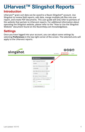
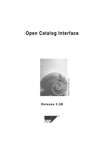
Quad-MSLINGSHOT INTERFACE CONTROL DOCUMENTTable of Contents1.2.3.4.5.6.7.8.9.10.11.DescriptionPayload ParametersRail Type PayloadsTab Type PayloadsPayload AccessMechanical RequirementsMaterialsElectricalPropulsion SystemsEnvironmentsRevision HistoryTable 1-1: Applicable DocumentsDoc No.RevSSP 57000RSSP 57003LSSP 51700TitlePressurized Payloads Interface RequirementsDocumentExternal Payload Interface Requirements DocumentSSP 52005FSSP 30233HPayload Safety Policy and Requirements for theInternational Space StationPayload Flight Equipment Requirements and Guidelinesfor Safety-Critical StructuresSpace Station Requirements for Materials and ProcessesSSP 30245PSpace Station Electrical Bonding RequirementsJSC 20793CMSFC-SPEC-522BCrewed Space Vehicle Battery Safety RequirementsDESIGN CRITERIA FOR CONTROLLING STRESS CORROSIONCRACKING1. SlingShot Overview1.1.0 SlingShot Description - The SlingShot system is modular CubeSat Deployer systemdesigned to mount on the Passive Common Berthing Mechanism (PCBM) face of theCygnus spacecraft and deploy CubeSats from the mounted Deployers. Each Deployerwill accommodate 6U of satellite hardware. The launcher can deploy a satellite groupinclusive of 1U satellites or a single 6U satellite or a combination of different size satellitestotaling up to 6U as dictated by the satellite design. See Figure 1-1.2SEOPSLLC.com/Quadminc.com
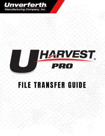
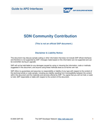
Quad-MSLINGSHOT INTERFACE CONTROL DOCUMENTFigure 1-1 SEOPS SlingShot Deployer Configuration on Face of Cygnus PCBMThe SlingShot launcher system is composed of the following major components to beassembled on orbit.1. Up to 9 preloaded 6U Deployers2. Internal control box for launcher selection and control3. Cygnus PCBM bulkhead bracketsThe SlingShot components are launched via any ISS Visiting Vehicle (in the pressurizedcompartment) and soft-stowed as component elements to be assembled on orbit.Hosted payloads may also be accommodated by the SlingShot system which canprovide external power/data and hard mounting via the SlingShot bulkhead brackets.Figures 3 through 5 illustrate the Deployer.3SEOPSLLC.com/Quadminc.com
Quad-MSLINGSHOT INTERFACE CONTROL DOCUMENTFigure 1-2 SlingShot PCBM Bulkhead Brackets4SEOPSLLC.com/Quadminc.com
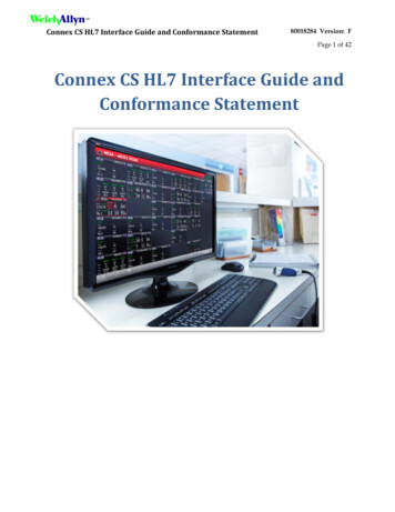
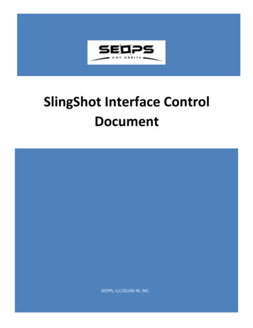
Quad-MSLINGSHOT INTERFACE CONTROL DOCUMENTFigure 1-3 SlingShot Deployer DetailsFigure 1-4 SlingShot Deployer Details5SEOPSLLC.com/Quadminc.com
Quad-MSLINGSHOT INTERFACE CONTROL DOCUMENTFigure 1-5 Door Hinge Details6SEOPSLLC.com/Quadminc.com
Quad-MSLINGSHOT INTERFACE CONTROL DOCUMENTEach SlingShot Deployer accommodates 6U satellites or combinations thereof. TheSlingShot components and payloads can be transported on any pressurized visitingvehicle (e.g. SpaceX Dragon, Cygnus, Progress, Soyuz, HII Transfer Vehicle (HTV), etc.) tothe ISS. Crew interaction with the SlingShot assembly involves transferring thecomponents from the launch vehicle to the Cygnus and assembly of up to 9 Deployersper mission containing satellites for deployment on the Cygnus. Operation of theSlingShot will occur after transfer to the ISS and subsequent installation by the ISS crewon the PCBM bulkhead in the Cygnus. The SlingShot Assembly is not powered or activeuntil deployment and power applied through the Cygnus for satellite deploymentactivity. This occurs far away from the ISS. Cygnus will maneuver SlingShot to the deploylocation and orientation. See Figure .Figure 1-6 SlingShot Deployer Concept of Operations7SEOPSLLC.com/Quadminc.com
Quad-MSLINGSHOT INTERFACE CONTROL DOCUMENT1.1.1 SlingShot Integration Schedule - Table 1-1 is a standard SlingShot IntegrationSchedule. The detailed payload schedule will be coordinated between SEOPS and thePayload Developer.Table 1-1: Standard SlingShot Integration ScheduleMilestone/ActivityLaunch-minus Dates(months)Regulatory Compliance Start (Spectrum CoordinationL – 14License, Remote Sensing License)Feasibility Study/Contract SigningL–9SEOPS/Customer Safety Data Call StartL-8.5SEOPS Safety Initial Assessment CompleteL-8.25Baseline Interface Control DocumentL-8Phase 0/1/2 Support Data from PD completeL-8Phase 0/1/2 Safety Data Package Submittal to NASAL-7Phase 0/1/2 Safety ReviewL-6Satellite-Separation System Fit CheckL-5Phase 3 Support Data from PD completeL-4.5Phase 3 Safety Data Package SubmittalL-4Phase 3 Safety ReviewL-3ISS Program Required Flight Acceptance testingL-2.5Payload Delivery to SEOPSL-2.5SEOPS Delivery to NASAL-2.51.1.2 SlingShot Fit Check - SEOPS will coordinate to complete mechanical interfacechecks between the satellite and the Deployer. Fit checks are conducted with thesatellite flight hardware and a SEOPS mockup Deployer. Use of flight-like engineeringqualification hardware in lieu of flight models must be coordinated with SEOPS.1.1.3 Satellite Delivery to SEOPS - The payload customer will deliver the integratedpayload to the SEOPS Houston facility, or another facility as determined by the ICD, bythe dates listed in the schedule. Any special requirements, such as lifting equipment,ground handling hardware, special handling instructions, ESD sensitivity, etc., will bedocumented in the payload specific ICD.1.1.4 SEOPS Inspection - SEOPS will inspect the combined payload assembly to verify itmeets the appropriate safety and ICD. This includes, but is not limited to, leak checks,mass properties and overall dimensions.1.1.5 SEOPS Data Gathering for Operations - SEOPS will assess the combined payloadassembly to develop products and procedures in support of crew interaction and onorbit assembly. In order to efficiently assemble the payload, minimize crew time, andSEOPSLLC.com/Quadminc.com8
Quad-MSLINGSHOT INTERFACE CONTROL DOCUMENTmaximize mission success, SEOPS will gather information on the payload including anoverall evaluation, pictures, and other products as needed. This information will be usedto create an effective way for crew to assemble and install the payload, developsupporting procedures, and ensure successful deployment of the satellite.1.1.6 SEOPS Testing - SEOPS will perform any agreed to testing of the completedassembly based on the Interface Control Agreement. This may include, but is notlimited to, grounding checks, bonding checks, fit checks. Any special requirements willbe documented in the payload specific ICD.1.1.7 Customer Ground Servicing - The customer is allowed to perform last minutepayload activities at the SEOPS facilities prior to final packaging, based on theagreements in the ICD, as long as these activities are part of the documented andverified payload design. No material or design chances are allowed at this phase ofthe processing. Once the payload has been delivered to the Cargo Mission Contract,no further payload servicing will be allowed. Any special requirements will bedocumented in the payload specific ICD.1.1.8 SEOPS Packaging and Delivery - SEOPS will deliver the loaded Deployer assemblyto the Cargo Mission Contracts area for incorporation into its final stowageconfiguration.1.1.9 Launch – The NASA Cargo Mission Contract Team is responsible for delivering thefinal stowed Deployer to the appropriate launch site facility and integration into the ISSvisiting vehicle for delivery to the ISS.1.1.10 Deployer Specification - This specification is intended for the Slingshotdeployment system and payload designers. This deployment system is unique in that itcan accommodate current standards of CubeSats such as 1U, 2U, 3U, 2UX2U (4U), and2Ux3U (6U), Tab & Rail type satellites, details are further in the document. The flexibilityof this system is achieved through a deployment that is perpendicular to the traditionaldeployment direction (Figure 1-7).9SEOPSLLC.com/Quadminc.com
Quad-MSLINGSHOT INTERFACE CONTROL DOCUMENTZ DEPLOYMENTFIGURE 1-7: DeploymentZ Y- Payload constraint, end plate coversonly tab or rail portion of the payloadY Y Payload constraint, end platecovers entire satellite faceFIGURE 1-8: Payload End Constraints10SEOPSLLC.com/Quadminc.com
Quad-MSLINGSHOT INTERFACE CONTROL DOCUMENT2. Payload Parameters3. Rail Type Payloads 3U (Figure 3-1 & 3-2) and 6U (Figure 3-3 & 3-4) rail payloads arecompatible with Slingshot. Optional “tuna can” is also compatible.“Tuna Can”11SEOPSLLC.com/Quadminc.com
Quad-MSLINGSHOT INTERFACE CONTROL DOCUMENT366MM MAX, 100MM MINFIGURE 3-1: “1U, 2U, 3U” Rail Payload12SEOPSLLC.com/Quadminc.com
Quad-MSLINGSHOT INTERFACE CONTROL DOCUMENT366MM MAX, 113.5MM MINFIGURE 3-2: “6U” Rail PayloadZ Y X 1mm MIN1.5mm MINFIGURE 3-3: “3U” Rail Satellites Integrated Into DeployerZ 13X Y SEOPSLLC.com/Quadminc.com
Quad-MSLINGSHOT INTERFACE CONTROL DOCUMENT1mm MIN1.5mm MINFIGURE 3-4: “6U” Rail Satellite Integrated Into Deployer4. Tab Type Payloads - 6U (Figure 4-1, 4-2 & 4-3) tab type payloads are compatible withSlingshot. 1U, 2U & 3U tab type satellites are also compatible but not shown (contactSEOPS for more information).14SEOPSLLC.com/Quadminc.com
Quad-MSLINGSHOT INTERFACE CONTROL DOCUMENT366mm MAX, 361mm MIN tab length (rest of payload can be smaller)FIGURE 4-1: “6U” Tab Payload15SEOPSLLC.com/Quadminc.com
Quad-MSLINGSHOT INTERFACE CONTROL DOCUMENTCSD Contact Zones11mmRecommended(subject toreview)12.7mm Recommended MINAll 4 Corners (subject to review)Note: Please reviewsection 5.2.2 for detailsFIGURE 4-2: “6U” Satellite Deployer ContactZ Y X 1mm MIN1.9mm MINFIGURE 4-3: “6U” Tab Satellite Integrated Into Deployer5. Payload Access - Payload access is provided via two (2) access panels in both sidesof the Deployer. The area that is accessible is shown for both rail and tabconfigurations in Figure 5-1, 5-2 and 5-3. Please note that if the length of the satellite isless than the max your payload may be placed with other payloads and the access inthe Y axis may be change. Example: A payload that is 200mm long may be placed16SEOPSLLC.com/Quadminc.com
Quad-MSLINGSHOT INTERFACE CONTROL DOCUMENTwith another payload that is 100mm long, being that the table is 366mm total lengthconsider the potential changes to access.Z (Deployment)X Y RemovableFigure 5-1: Payload AccessIt is also possible to remove the end plate for satellite access depending on needs ofthe payload.17SEOPSLLC.com/Quadminc.comRemovable
Quad-MSLINGSHOT INTERFACE CONTROL DOCUMENTZ (Deployment)Y Example:FIGURE 5-2: “3U & 6U” Rail Side Access (Both Sides)Y Z (Deployment)Example:FIGURE 5-3: “6U” Tab Side Access (Both Sides)18SEOPSLLC.com/Quadminc.com
Quad-MSLINGSHOT INTERFACE CONTROL DOCUMENT6. Mechanical Requirements: 6.1.0 Safe/Arm plug, if necessary, shall reside in specified access zones. 6.1.1 All deployables must be constrained during deployment via burn wires orother mechanisms. This requirement may be waved after review from SEOPS. 6.1.2 No debris shall be generated that will inhibit separation. 6.1.3 The maximum dimensions stated in this document are the payload’sdynamic envelope and shall include all load cases (vibration, thermal, acoustic,etc.). 6.1.4 Maximum dimensions stated in this document apply after plating on allsurfaces. 6.1.5 Contact SEOPS to determine if payload inhibits (activation switches) arerequired. If required, locating on the –Z table face such that they contact theCSD’s deployment plate is recommended. The deployable contact areas mayalso be used but consider the effect of tolerance build-up & frictional forces inthe Deployer. 6.1.6 It is not desirable to have separation switches on the Y face of the satellite.Roller switches on the Y face are preferred. Roller/lever/plunger type switcheson the Z- table face are preferred. 6.1.7 Activation switches must maintain a deactivated state until afterdeployment. The activation throw of the switch and the Deployer gap betweenthe satellite and the Deployer Z-/Y face must be taken into consideration (seeFigure 3-3, 3-4 & 4-3). The Y gap is part of the Deployers design and will not befully contacting the satellite so deployment can be achieved. Assume there willbe a gap as shown (Figure 3-3, 3-4 & 4-3). 6.1.7 No appendages or any part of the satellite shall contact the walls of theDeployer, pending SEOPS review. 6.2.0 Tab Specific:o 6.2.1 Tabs shall be aluminum alloy with yield strength 56ksi. 7075-T7351 iscommon but numerous other alloys also meet this strength requirement.o 6.2.2 The two tabs and the structure that contacts the CSD doors on theZ face (see Figure 4-2) are the only required features of the payload. Therest of the payload may be any shape that fits within the maximumdynamic envelope. The minimum contact shown can be reviewed bySEOPS to verify the payloads compatibility with the Deployer as it ispossible to have contact anywhere along the indicated area so long as itgives contact to properly constrain the satellite during launch and doesnot interfere with deployment. 6.3.0 Rail Specific:o 6.3.1 Rail end separation plungers (example 3.2.17 Cal Poly CubeSatDesign Specification Rev 13) must be removed before integration with theDeployer.19SEOPSLLC.com/Quadminc.com
Quad-MSLINGSHOT INTERFACE CONTROL DOCUMENT7. Materials: 7.1.0 Stress corrosion resistant materials used from MSFC-SPEC-522 are preferred.Table II materials will be reviewed by SEOPS and Table III materials shall beavoided. 7.1.1 Beryllium, cadmium, mercury, silver or other materials prohibited by SSP30233 shall not be used. Any hazardous materials must be coordinated withSEOPS. 7.1.2 Payloads shall comply with NASA guidelines for selecting all non-metallicmaterials based on available outgassing data. Satellites shall not utilize any nonmetallic materials with a Total Mass Loss (TML) greater than 1.0 percent or aCollected Volatile Condensable Material (CVCM) value of greater than 0.1percent. A list of all non-metallic parts (which may be included in the Bill ofMaterials below) should include all projected areas of non-metallic parts.Outgassing data can be found at https://outgassing.nasa.gov/. 7.1.3 A bill of materials (BOM) must be provided to SEOPS to verify the type ofmaterials used and material masses.8. Electrical:8.1.0 Electrical System Design and Inhibits. All Electrical power shall be internal toSatellites. Satellite systems must be safe without Electrical services. Satellite electronicssystems design shall adhere to the following requirements.1) The Satellite operations shall not begin until a minimum of 30 minutes afterdeployment. Only an onboard timer system may be operable during this 30minute post deploy time frame. Any timer operation initiated by satellite inhibitsmust automatically reset should inadvertent separation switch operation occur.2) If activation of the satellite creates a hazard (e.g. activation of a powerful radiotransmitter, activation of propulsion system, activation of a non-eye safe laser,etc.) the Satellite Electrical system design shall incorporate a minimum of three(3) inhibit switches actuated by physical deployment switches as shown in Figure. If activation of the Satellite does not present a hazard to crew or hardware oneor two inhibit switches are satisfactory. Contact SEOPS for further clarification.3) The Satellite Electrical system design shall not permit the battery charging circuitto energize the satellite systems (load), including flight computer (see Figure ).This restriction applies to all charging methods.4) Remove Before Flight (RBF) pins are required. Arming switch or captive jumpersmay be an acceptable alternative; contact SEOPS.5) The RBF pin shall prevent any power from any source operating any satellitefunctions except for pre-integration battery charging.6) RBF pins must be capable of remaining in place during integration with theDeployer.20SEOPSLLC.com/Quadminc.com
Quad-MSLINGSHOT INTERFACE CONTROL DOCUMENT7) All RBF pins, switches, or jumpers utilized as primary Electrical system and RBFinhibits must be accessible for removal at the completion of flight integrationwith the Deployer.8) All solar arrays must use an inhibit to preclude flow of current from the solar arraysinto the bus in the event they are illuminated prior to deploy where busactuation presents a hazard.9) All spacecraft components shall be Electrically bonded per SSP 30245 to ensurethe spacecraft is free from Electrical shock and static discharge hazards.Typically, spacecraft components may be bonded by either nickel plating orchemical film treated faying surfaces or dedicated bonding straps. Adesignated Single Point Ground shall be accessible on the Payload’s exteriorconductive surface.Figure 8-1: Satellite Electrical Subsystem Block Diagram (note: RBF pins switches notshown)- Reference Example 8.2.1 Batteries - Battery requirements for spacecraft flight onboard or near the ISS arederived from the NASA requirement document JSC 20793 Crewed Space VehicleBattery Safety Requirements. Specific provisions for battery use are designed to assurethat a battery is safe for ground personnel and ISS crew members to handle and/oroperate during all applicable mission phases and particularly in an enclosedenvironment of a crewed space vehicle. These NASA provisions also assure that thebattery is safe for use in launch vehicles, as well as in unpressurized spaces adjacent tothe habitable portion of a space vehicle. The required provisions encompass hazardcontrols, design evaluation, and verification. Evaluation of the battery system must becomplete prior to certification for flight and ground operations. To support this21SEOPSLLC.com/Quadminc.com
Quad-MSLINGSHOT INTERFACE CONTROL DOCUMENTobjective information on the battery system must be provided to SEOPS as soon aspossible. For example, certain battery cell chemistries and battery configurations maytrigger higher scrutiny to protect against thermal runaway propagation. It is imperativethat SEOPS receive all requested technical data as early as possible to assure thenecessary safety features are present to control the hazards associated with aparticular battery design. True in nearly every case, redesign efforts greatly impact thepayload developer both in cost and schedule. This can often be avoided by consultingwith SEOPS before hardware is actually manufactured (if possible). Cell/Battery testingassociated with the verification of the safety compliance must be completed prior tosafety certification of the spacecraft. To be compliant to the requirements herein,every battery design, along with its safety verification program, its ground and/or onorbit usage plans, and its post-flight processing should be evaluated and approved bythe customer and SEOPS.8.2.2 Battery Hazards - The possible sources of battery hazards are listed below and shallbe identified for each battery system. Applicable hazards will be evaluated todetermine and to identify design, workmanship, and other features to be used forhazard control (Electrical, mechanical, and/or thermal).Potential Battery Hazards: Fire/Explosion Hazard Flammability Venting of Battery Enclosure Burst of Pressurized Battery Chemistries Overcharge Failure/Over-discharge Failure External Short Circuit Internal Short Circuit Failure Thermal Runaway Propagation Chemical Exposure Hazards Mechanical Failure Seals and Vents Electrical Hazards Extreme Environment Temperature Hazards8.2.3 Battery Types - Although any battery may be made safe to fly in the crewedspace vehicle environment there are some batteries that are impractical to make safe.For example, lithium-sulfur dioxide cells have built-in overpressure vents that will releaseSO2 (sulfur dioxide) gas and other electrolyte components that are highly toxic; thus,these are unacceptable in the habitable area of a space vehicle. However, thesechemistries have been used safely in the non-pressurized areas of crewed spacecraft.Often the cells used in batteries for crewed space vehicle are commercially available.Battery types Typically used in spacecraft include: Alkaline-manganese primary LeClanche (carbon-zinc) primary22SEOPSLLC.com/Quadminc.com
Quad-MSLINGSHOT INTERFACE CONTROL DOCUMENTLead-acid secondary cells having immobilized electrolyteLithium/lithium-ion polymer secondary (including lithium-polymer variation)Lithium metal anode primary cells having the following cathodic (positive) activematerials: Poly-carbon monofluoride Iodine Manganese dioxide Silver chromate Sulfur dioxide (external to habitable spaces only) Thionyl chloride Thionyl chloride with bromine chloride complex additive (Li-BCX) Iron disulfide Lithium sulfur Mercuric oxide-zinc primary Nickel-cadmium secondary Nickel-metal hydride secondary Silver-zinc primary and secondary Zinc-air primary Sodium-sulfur secondary (external to habitable space) Thermal batteriesNote: Pressurized battery chemistries require coordination with SEOPS. 8.2.4 Required Battery Flight Acceptance Testing - Acceptance screening tests arerequired for all cells intended for flight to ensure the cells will perform in the requiredload and environment without leakage or failure. See Appendix A for the detailedbattery testing plan.8.2.5 Internal Short - Protection circuity and safety features shall be implemented at thecell level. Application of all cells shall be reviewed by SEOPS.Charger circuit and protection circuit schematics shall be reviewed andevaluated for required failure tolerance.8.2.6 External Short Circuit – Circuit interrupters that are rated well below the battery's peak current sourcecapability should be installed in the battery power circuit. Interrupters may befuses, circuit breakers, thermal switches, PTCs, or other effective devices. Circuitinterrupters other than fuses should be rated at a value that is equal to or lowerthan the maximum current that the cell is capable of handling without causingventing, smoke, Explosion, fire, or thermal runaway. The battery case is usually grounded/bonded to the structure; the interruptersshould be in the ground (negative) leg of a battery where the negative terminalis connected to ground. Where the circuit is “floating,” as in plastic battery cases23SEOPSLLC.com/Quadminc.com
Quad-M SLINGSHOT INTERFACE CONTROL DOCUMENTused in those for portable electronic devices, the circuit interrupters can beplaced in either leg. In either case, the circuit interrupters should be placed asclose to the cell or battery terminals as the design will allow maximizing the zoneof protection.All inner surfaces of metal battery enclosures shall be anodized and/or coatedwith a non-Electrically conductive electrolyte-resistant paint to prevent asubsequent short circuit hazard.The surfaces of battery terminals on the outside of the battery case shall beprotected from accidental bridging.Battery terminals that pass through metal battery enclosures shall be insulatedfrom the case by an insulating collar or other effective means.Wires inside the battery case shall be insulated, restrained from contact with cellterminals, protected against chafing, and physically constrained frommovement due to vibration or shock.In battery designs greater than 50 Vdc, corona-induced short circuits (highvoltage induced gas breakdown) shall be prevented.8.2.7 Battery Charging – Battery charging is not permitted on-orbit but can beperformed on the ground prior to hardware turnover, including in the Deployer.8.2.8 Battery Energy Density – For battery designs greater than 80-Wh energy employinghigh specific energy cells (greater than 80 watt-hours/kg, for example, lithium-ionchemistries) require additional assessment by SEOPS due to potential hazard in theevent of single-cell, or cell-to-cell thermal runaway. The best design practice forbatteries of this size is physical separation of or thermal barriers between the batterycells to prevent thermal runaway situations.8.2.8 Lithium Polymer “Pouch” Cells – Lithium Polymer Cells i.e. “pouch cells” shall berestrained at all times to prevent inadvertent swelling during storage, cycling, and lowpressure or vacuum environments with pressure restraints on the wide faces of the cellsto prevent damage due to pouch expansion. Coordinate with SEOPS for guidance onspecific implementation.24SEOPSLLC.com/Quadminc.com
Quad-MSLINGSHOT INTERFACE CONTROL DOCUMENT8.3.0 Radio Transmitter System. Satellite providers shall fill in the following table of RFtransmitter parameters to evaluate any potential hazards or RF interferences with ISS orCygnus.Table Error! No text of specified style in document.-1: RF Transmitter DetailsTransmitter SpecificationManufacturerModelModel #:S/N:Maximum power output to antenna [W]Maximum transmitter field strength (volts/meter); assume 1 meterfrom the source and transmitter radiating with deployedantennaTX ManufacturerTX Model NoTX Antenna Manufacturer:Antenna Gain: [dBi]Frequency Upper [MHz]Frequency lower [MHz]Circuit Loss: [dB]Antenna Type: Other, dipole, helix, horn, loop, monopole,patch, phased array, reflector, slot, spiralAntenna Polarization: [Other, Horizontal, Left Handed ElliptICDl,Right Handed ElliptICDl, VertICDlAntenna Axial Ratio: [dB]Antenna location (with respect to CubeSat body)25SEOPSLLC.com/Quadminc.com
Quad-MSLINGSHOT INTERFACE CONTROL DOCUMENT8.3.1 – Electromagnetic Interference for On-Orbit - Satellites may be exposed to thefollowing EMI environment on the ISS.FREQUENCY14 kHz - 400 MHz400 MHz - 450 MHz450 MHz - 1 GHz1 GHz - 5 GHz5 GHz - 6 GHz6 GHz - 10 GHz13.7 GHz - 15.2 GHz55RS03PL LIMIT (V/m)3025602025COMMENT: The less stringent RS03PL limit was developed to envelope the electricfields generated by ISS transmitters and ground–based radars tasked to perform spacesurveillance and tracking. Ground–based radars that are not tasked to track the ISSand search radars that could momentarily sweep over the ISS are not enveloped bythe relaxed RS03PL. For most end items, the minimal increase of EMI risk for thereduced limits is acceptable.The RS03PL limit does not account for module electric field shielding effectivenessthat could theoretically reduce the limits even more.26SEOPSLLC.com/Quadminc.com
Quad-MSLINGSHOT INTERFACE CONTROL DOCUMENT9. Propulsion Systems9.0.1 – Propulsion System - The propulsion system will need to be assessed for hazardpotential. SEOPS will assist in the identification of hazards. Mechanical hazards may berelated to pressure containment, flow containment, leakage, etc. Systems may alsohave hazard potential if inadvertent operation of the propulsion system in or around ISScould cause a catastrophic or Critical hazard. This particular hazard can be mitigatedby simply requiring activation of two or more thrusters to provide lateral motion (i.e. ifone thruster were inadvertently actuated it would only impose rotational motion to thespacecraft). Also, low thrust (e.g. ion thrusters) limit hazard potential by providing longresponse times to mitigate any collision hazards that may be present. Depending onhazard potential, both mechanical and electrical fault tolerance may be required.Systems with toxic propellant are not be allowed onboard ISS. Propellants withexplosive potential may not be approvable. Acceptable propellant type must becoordinated with SEOPS.9.0.2 – Pressure Vessels - Pressure vessels (i.e. any vessel able to hold more than 2 atm ofpressure at any time in its operation) may be made acceptable for Flight Safety withproper controls for any hazard potential both for inside ISS and outside ISS. Payloadsshould expect to provide documentation with respect to the materials used, tankhistory (including cycles and life time assessment) and control measure to assure tankintegrity (damage control plan), testing performed, fracture control measures planned,inspection process and methods, etc. wherever hazard potential is present. All pressurevessels shall be DOT certified or have a DOT issued waiver for transportation across theUS. Use of non-DOT certified pressure vessels generally is not be permitted. Exceptionsmust be coordinated with SEOPS. Systems will have to demonstrate via test thatrequired factors of safety are present for tanks, lines and fittings that can be exposed tomaximum design pressure. Pressure vessels and components procured from third partyvendors must have proper certification records or the customer must develop theappropriate records to assure that the systems are safe for satellite use.27SEOPSLLC.com/Quadminc.com
Quad-MSLINGSHOT INTERFACE CONTROL DOCUMENT10. Environments10.0.1 Ground Handling and Transportation Loads - Payload safety-critical structuresshall (and other payload structures should) provide positive margins of safety whenexposed to these accelerations.TABLE 10-1. GROUND HANDLING AND TRANSPORTATION LOAD FACTORSNotes:1)The reference frame for the ground handling and transportation load factorswith respect to the directions of motion is as follows:X: Longitudinal direction along axis of motion.Y: Y axis is perpendicular to the x and z axes and completes the right handedcoordinate system.Z: Z axis is perpendicular to the x and y axis. Positive direction is verticallyupward. Gravity (g) is acting in the z axis in the negative direction.2) (I) indicates that the loads occur independently in the three directions (exceptfor gravity). (S) indicates that the loads occur simultaneously.3) These levels envelope the maximum ground handling and transportation loads.10.0.2 Acceleration Loads - Payload safety-critical structures shall (and other payloadstructures should) provide positive margins of safety when exposed to the accelerationsdocumented in Table 10-2 at the CG of the item, with all six degrees of freedom actingsimultaneously. The acceleration values are applicable to both soft stowed and hardmounted hardware. (Per SSP 57000, Section D.3.1.1)Table 10-2: Launch Load Factors EnvelopeLaunch28Nx (g)Ny (g)Nz (g) 7.7/-9.0 /- 11.6 /- 11.6RxRyRz(rad/sec 2) (rad/sec 2) (rad/sec 2) /- 70.8 /- 70.8 /- 70.8SEOPSLLC.com/Quadminc.com
Quad-MSLINGSHOT INTERFACE CONTR
1.1.0 SlingShot Description - The SlingShot system is modular CubeSat Deployer system designed to mount on the Passive Common Berthing Mechanism (PCBM) face of the Cygnus spacecraft and deploy CubeSats from the mounted Deployers. Each Deployer will accommodate 6U of satellite hardware. The launcher can deploy a satellite group

![[Type here] BUG OUT BAG CHECKLIST - Skilled Survival](/img/14/bug-out-bug-out-bag-checklist-v3.jpg)