Transcription
Adafruit Feather HUZZAH ESP8266Created by lady zah-esp8266Last updated on 2022-07-27 03:33:49 PM EDT Adafruit IndustriesPage 1 of 65
Table of ContentsOverview5Pinouts8 Power PinsLogic pinsSerial pinsI2C & SPI pinsGPIO pinsAnalog PinsOther control pinsNC PinsAssembly Header Options!Soldering in Plain HeadersPrepare the header strip:Add the breakout board:And Solder!Soldering on Female HeaderTape In PlaceFlip & Tack SolderAnd Solder!Power Management 34Install the Arduino IDE 1.6.8 or greaterInstall the ESP8266 Board PackageSetup ESP8266 SupportBlink TestConnecting via WiFiWipperSnapper Setup 28Open up serial consoleHello world!Scanning & Connecting to WiFiWebClient exampleUsing Arduino IDE 23Battery USB PowerPower SuppliesMeasuring BatteryENable pinAlternative Power OptionsUsing NodeMCU Lua 1442What is WipperSnapperSign up for Adafruit.ioAdd a New Device to Adafruit IOFeedbackTroubleshooting"Uninstalling" WipperSnapper Adafruit IndustriesPage 2 of 65
WipperSnapper Usage 47Blink a LEDRead a Push-ButtonRead an I2C SensorGoing FurtherUsing MicroPython60Downloads60 Datasheets & FilesMore info about the ESP8266SchematicRev G SchematicFabrication PrintESP8266 F.A.Q. Adafruit Industries62Page 3 of 65
Adafruit IndustriesPage 4 of 65
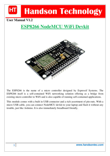
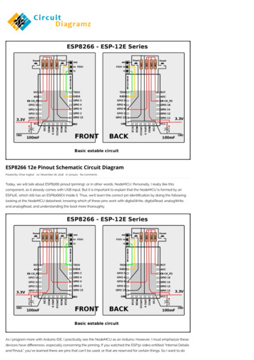
OverviewFeather is the new development board from Adafruit, and like it's namesake it is thin,light, and lets you fly! We designed Feather to be a new standard for portablemicrocontroller cores.This is the Adafruit Feather HUZZAH ESP8266 - our take on an 'all-in-one' ESP8266WiFi development board with built in USB and battery charging. Its an ESP8266 WiFimodule with all the extras you need, ready to rock! We have other boards in theFeather family, check'em out here (https://adafru.it/jAQ). Adafruit IndustriesPage 5 of 65
At the Feather HUZZAH's heart is an ESP8266 WiFi microcontroller clocked at 80MHz and at 3.3V logic. This microcontroller contains a Tensilica chip core as well as afull WiFi stack. You can progam the microcontroller using the Arduino IDE for an easyto-run Internet of Things core. We wired up a USB-Serial chip that can upload code ata blistering 921600 baud for fast development time. It also has auto-reset so nonoodling with pins and reset button pressings.To make it easy to use for portable projects, we added a connector for any of our 3.7VLithium polymer batteries and built in battery charging. You don't need a battery, it willrun just fine straight from the micro USB connector. But, if you do have a battery, youcan take it on the go, then plug in the USB to recharge. The Feather will automaticallyswitch over to USB power when its available. Adafruit IndustriesPage 6 of 65
Here's some handy specs! Measures 2.0" x 0.9" x 0.28" (51mm x 23mm x 8mm) without headers soldered in Light as a (large?) feather - 6 grams ESP8266 @ 80MHz or 160 MHz with 3.3V logic/power 4MB of FLASH (32 MBit) 3.3V regulator with 500mA peak current output CP2104 USB-Serial converter onboard with 921600 max baudrate for uploading Auto-reset support for getting into bootload mode before firmware upload 9 GPIO pins - can also be used as I2C and SPI 1 x analog inputs 1.0V max Built in 100mA lipoly charger with charging status indicator LED Pin #0 red LED for general purpose blinking. Pin #2 blue LED for bootloadingdebug & general purpose blinking Power/enable pin 4 mounting holes Reset button Adafruit IndustriesPage 7 of 65
Comes fully assembled and tested, with a USB interface that lets you quickly use itwith the Arduino IDE or NodeMCU Lua. (It comes preprogrammed with the Luainterpretter) We also toss in some header so you can solder it in and plug into asolderless breadboard. Lipoly battery and USB cable not included (but we do havelots of options in the shop if you'd like!)Pinouts Adafruit IndustriesPage 8 of 65
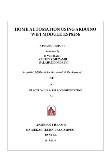
Power Pins GND - this is the common ground for all power and logic BAT - this is the positive voltage to/from the JST jack for the optional Lipolybattery USB - this is the positive voltage to/from the micro USB jack if connected EN - this is the 3.3V regulator's enable pin. It's pulled up, so connect to groundto disable the 3.3V regulator Adafruit IndustriesPage 9 of 65
3V - this is the output from the 3.3V regulator, it can supply 500mA peak (try tokeep your current draw under 250mA so you have plenty for the ESP8266'spower requirements!)Logic pinsThis is the general purpose I/O pin set for the microcontroller. All logic is 3.3VThe ESP8266 runs on 3.3V power and logic, and unless otherwise specified,GPIO pins are not 5V safe! The analog pin is also 1.0V max!Serial pinsRX and TX are the serial control and bootloading pins, and are how you will spendmost of your time communicating with the ESP moduleThe TX pin is the output from the module and is 3.3V logic.The RX pin is the input into the module and is 5V compliant (there is a level shifter onthis pin)These are connected through to the CP2104 USB-to-Serial converter so they should not be connected to or used unless you're super sure you want to because you willalso be getting the USB traffic on these! Adafruit IndustriesPage 10 of 65
I2C & SPI pinsYou can use the ESP8266 to control I2C and SPI devices, sensors, outputs, etc. Whilethis is done by 'bitbanging', it works quite well and the ESP8266 is fast enough tomatch 'Arduino level' speeds.In theory you can use any pins for I2C and SPI but to make it easier for people usingexisting Arduino code, libraries, sketches we set up the following: I2C SDA GPIO #4 (default) I2C SCL GPIO #5 (default)If you want, you can connect to I2C devices using other 2 pins in the Arduino IDE, bycalling Wire.pins(sda, scl) before any other Wire code is called (so, do this atthe begining of setup() for exampleLikewise, you can use SPI on any pins but if you end up using 'hardware SPI' you willwant to use the following: SPI SCK GPIO #14 (default) SPI MOSI GPIO #13 (default) SPI MISO GPIO #12 (default) Adafruit IndustriesPage 11 of 65
GPIO pinsThis breakout has 9 GPIO: #0, #2, #4, #5, #12, #13, #14, #15, #16 arranged at the topedge of the Feather PCBAll GPIO are 3.3V logic level in and out, and are not 5V compatible. Read the fullspec sheet (https://adafru.it/f1E) to learn more about the GPIO pin limits, but be awarethe maximum current drawn per pin is 12mA.These pins are general purpose and can be used for any sort of input or output. Mostalso have the ability to turn on an internal pullup. Many have special functionality:GPIO #0, which does not have an internal pullup, and is also connected a red LED.This pin is used by the ESP8266 to determine when to boot into the bootloader. If thepin is held low during power-up it will start bootloading! That said, you can always useit as an output, and blink the red LED - note the LED is reverse wired so setting thepin LOW will turn the LED on.GPIO #2, is also used to detect boot-mode. It also is connected to the blue LED that isnear the WiFi antenna. It has a pullup resistor connected to it, and you can use it asany output (like #0) and blink the blue LED.GPIO #15, is also used to detect boot-mode. It has a pulldown resistor connected to it,make sure this pin isn't pulled high on startup. You can always just use it as an outputGPIO #16 can be used to wake up out of deep-sleep mode, you'll need to connect itto the RESET pinAlso note that GPIO #12/13/14 are the same as the SCK/MOSI/MISO 'SPI' pins! Adafruit IndustriesPage 12 of 65
Analog PinsThere is also a single analog input pin called A. This pin has a 1.0V maximumvoltage, so if you have an analog voltage you want to read that is higher, it will haveto be divided down to 0 - 1.0V rangeOther control pinsWe have a few other pins for controlling the ESP8266 RST - this is the reset pin for the ESP8266, pulled high by default. When pulleddown to ground momentarily it will reset the ESP8266 system. This pin is 3.3Vlogic only EN (CH PD) - This is the enable pin for the ESP8266, pulled high by default.When pulled down to ground momentarily it will reset the ESP8266 system. Thispin is 3.3V logic only Adafruit IndustriesPage 13 of 65
NC PinsThe rest of the pins are labeled NC which means Not Connected - they are notconnected to anything and are there as placeholders only, to maintain physicalcompatibility with the other boards in the Feather line!AssemblyWe ship Feathers fully tested but without headers attached - this gives you the mostflexibility on choosing how to use and configure your FeatherHeader Options!Before you go gung-ho on soldering, there's a few options to consider!The first option is soldering in plain maleheaders, this lets you plug in the Featherinto a solderless breadboard Adafruit IndustriesPage 14 of 65
Another option is to go with socket femaleheaders. This won't let you plug theFeather into a breadboard but it will letyou attach featherwings very easily Adafruit IndustriesPage 15 of 65
We also have 'slim' versions of the femaleheaders, that are a little shorter and give amore compact shape Adafruit IndustriesPage 16 of 65
Finally, there's the "Stacking Header"option. This one is sort of the best-of-bothworlds. You get the ability to plug into asolderless breadboard and plug afeatherwing on top. But its a little bulkySoldering in Plain HeadersPrepare the header strip:Cut the strip to length if necessary. It willbe easier to solder if you insert it into abreadboard - long pins down Adafruit IndustriesPage 17 of 65
Add the breakout board:Place the breakout board over the pins sothat the short pins poke through thebreakout padsAnd Solder!Be sure to solder all pins for reliableelectrical contact.(For tips on soldering, be sure to check outour Guide to Excellent Soldering (https://adafru.it/aTk)). Adafruit IndustriesPage 18 of 65
Solder the other strip as well. Adafruit IndustriesPage 19 of 65
You're done! Check your solder jointsvisually and continue onto the next stepsSoldering on Female HeaderTape In PlaceFor sockets you'll want to tape them inplace so when you flip over the board theydon't fall out Adafruit IndustriesPage 20 of 65
Flip & Tack SolderAfter flipping over, solder one or twopoints on each strip, to 'tack' the header inplace Adafruit IndustriesPage 21 of 65
And Solder!Be sure to solder all pins for reliableelectrical contact.(For tips on soldering, be sure to check outour Guide to Excellent Soldering (https://adafru.it/aTk)). Adafruit IndustriesPage 22 of 65
You're done! Check your solder jointsvisually and continue onto the next stepsPower ManagementDon't power the Huzzah ESP8266 with a CanaKit 5V power supply, these powersupplies have been destroying the CP2104 chip. Adafruit IndustriesPage 23 of 65
Battery USB PowerWe wanted to make our Feather boards easy to power both when connected to acomputer as well as via battery.There's two ways to power a Feather:1. You can connect with a USB cable (just plug into the jack) and the Feather willregulate the 5V USB down to 3.3V.2. You can also connect a 4.2/3.7V Lithium Polymer (LiPo/LiPoly) or Lithium Ion(LiIon) battery to the JST jack. This will let the Feather run on a rechargeablebattery.When the USB power is powered, it will automatically switch over to USB for power,as well as start charging the battery (if attached). This happens 'hot-swap' style so youcan always keep the LiPoly connected as a 'backup' power that will only get usedwhen USB power is lost.The JST connector polarity is matched to Adafruit LiPoly batteries. Using wrongpolarity batteries can destroy your Feather. Adafruit IndustriesPage 24 of 65
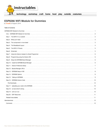
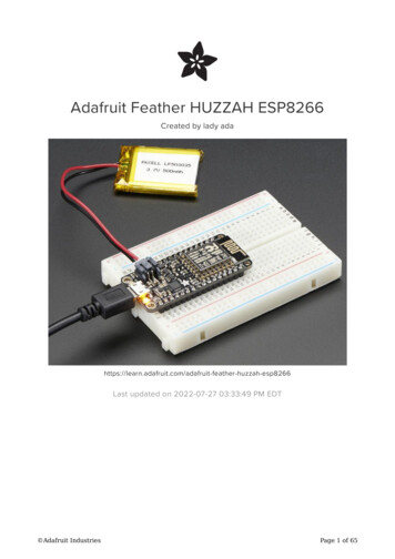
The above shows the Micro USB jack (left), LiPoly JST jack (top left), as well as the3.3V regulator and changeover diode (just to the right of the JST jack) and the LiPolycharging circuitry (right below the regulator).There's also a CHG LED next to the USB jack, which will light up while the battery ischarging. This LED might also flicker if the battery is not connected, it's normal.The charge LED is automatically driven by the LiPoly charger circuit. It will try todetect a battery and is expecting one to be attached. If there isn't one it mayflicker once in a while when you use power because it's trying to charge a (nonexistent) battery. It's not harmful, and its totally normal!Power SuppliesYou have a lot of power supply options here! We bring out the BAT pin, which is tiedto the LiPoly JST connector, as well as USB which is the 5V from USB if connected.We also have the 3V pin which has the output from the 3.3V regulator. We use a500mA peak regulator. While you can get 500mA from it, you can't do it continuouslyfrom 5V as it will overheat the regulator.We use this to power the ESP8266 which can draw spikes of 250 mA (although itsnot continuous).You should be able to budget about 250mA current available from the regulator,which will leave plenty for the WiFi module. Adafruit IndustriesPage 25 of 65
Measuring BatteryIf you're running off of a battery, chances are you wanna know what the voltage is at!That way you can tell when the battery needs recharging. LiPoly batteries are 'maxedout' at 4.2V and stick around 3.7V for much of the battery life, then slowly sink downto 3.2V or so before the protection circuitry cuts it off. By measuring the voltage youcan quickly tell when you're heading below 3.7V.Since the ESP8266 does not have multiple ADC pins, we didn't want to 'sacrifice' onefor LiPoly battery monitoring. However we do have a tutorial that mentions how to doit, using two resistors. You can check out the wiring diagram here (use the VBat pin tomeasure) (https://adafru.it/jCY) and the code here (https://adafru.it/NMb).ENable pinIf you'd like to turn off the 3.3V regulator, you can do that with the EN(able) pin. Simplytie this pin to Ground and it will disable the 3V regulator. The BAT and USB pins willstill be powered. Adafruit IndustriesPage 26 of 65
Alternative Power OptionsThe two primary ways for powering a feather are a 3.7/4.2V LiPo battery plugged intothe JST port or a USB power cable.If you need other ways to power the Feather, here's what we recommend: For permanent installations, a 5V 1A USB wall adapter (https://adafru.it/duP) willlet you plug in a USB cable for reliable power For mobile use, where you don't want a LiPoly, use a USB battery pack! (https://adafru.it/e2q) If you have a higher voltage power supply, use a 5V buck converter (https://adafru.it/DHs) and wire it to a USB cable's 5V and GND input (https://adafru.it/DHu)Here's what you cannot do: Do not use alkaline or NiMH batteries and connect to the battery port - this willdestroy the LiPoly charger and there's no way to disable the charger Do not use 7.4V RC batteries on the battery port - this will destroy the boardThe Feather is not designed for external power supplies - this is a design decision tomake the board compact and low cost. It is not recommended, but technicallypossible: Connect an external 3.3V power supply to the 3V and GND pins. Notrecommended, this may cause unexpected behavior and the EN pin will nolonger. Also this doesn't provide power on BAT or USB and some Feathers/Wings use those pins for high current usages. You may end up damaging yourFeather. Connect an external 5V power supply to the USB and GND pins. Notrecommended, this may cause unexpected behavior when plugging in the USBport because you will be back-powering the USB port, which could confuse ordamage your computer. Adafruit IndustriesPage 27 of 65
Using NodeMCU LuaEach Feather HUZZAH ESP8266 breakout comes pre-programmed with NodeMCU'sLua interpreter. As of this writing, we ship with NodeMCU 0.9.5 build 20150318powered by Lua 5.1.4 but it may be more recentLua is still a work in progress, so we strongly recommend visiting NodeMCU and updating your Lua version to the very latest as they have the ability to make you the latestcontinuous build (https://adafru.it/wAq). Then follow their guide on how to updateLua! (https://adafru.it/wAr)The Lua interpreter runs on the ESP8266 and you can type in commands and readout the results over serial. In order to upload code to the ESP8266 and use the serialconsole, connect any data-capable micro USB cable to the Feather HUZZAH and theother side to your computer's USB port. Install the required CP2104 USB driver tohave the COM/Serial port appear properly (https://adafru.it/jCs)Don't forget to visit esp8266.com for the latest and greatest in ESP8266 news,software and gossip! (https://adafru.it/f1F)Don't forget to install the USB driver for the CP2104 USB-to-Serial chip!Open up serial consoleNext up, on your computer, use a serial console program such as CoolTerm (Mac) or Putty (Windows) or screen (linux). Teraterm seems to dislike the initial 74400bps datastream from the ESP8266 so you can try it but you'll possibly need to reset theterminal software. Connect up to the COM or Serial port used by your cable, at 9600 Baud Make sure you have turned off any hardware handshake or flow control Putty isn't good with pasting code in, so you may not be able to copy-n-paste! Also make sure you have line endings set to CRLF "\r\n"Use any serial console program you like, we just happen to be used to Putty! Adafruit IndustriesPage 28 of 65
Once the terminal software is connected, click the Reset button on the FeatherHUZZAH ESP8266 board to reset it and have it print out the welcome message:If you don't get this message, first check that the red/blue leds flickered when youpress the reset button. If they didnt, make sure you've got the right baud rateselected in the software (9600) Adafruit IndustriesPage 29 of 65
Hello world!Ok we can now turn on an LED. There is a red LED on each board, connected to GPIO#0NodeMCU Lua's pinouts are not the same as the Arduino/gcc pinouts. We printthe Arduino pinouts on the board so watch out!The Lua documentation for the ESP8266 has GPIO #4 and #5 swapped so if #4/#5 aren't working for you, try swapping!Pin NotesPCB/ArduinoNodeMCU/LuaNo pullups!03243941529111012126CHPD (Note, don't use this pin or set itto be an output!) Adafruit IndustriesPage 30 of 65
137145158160So to set the pin #0 LED on and off (which would be pin #3 in Lua) first make it anoutput:gpio.mode(3, gpio.OUTPUT)Turn the LED on with:gpio.write(3, gpio.LOW)And off with:gpio.write(3, gpio.HIGH)You can make this a little more automated by running a longer script.For longer text, pasting can be difficult as the lua interpreter needs a little delay timebetween characters and also require CR-LF settings. For that reason you may want topaste each line and then hit return manually.while 1 dogpio.write(3, gpio.HIGH)tmr.delay(1000000)-- wait 1,000,000 us 1 secondgpio.write(3, gpio.LOW)tmr.delay(1000000)-- wait 1,000,000 us 1 secondendThe LED will now be blinking on and off.Note that since its in a loop, its not possible to get it to stop via the interpreter. Tostop it, click the Reset button again! Adafruit IndustriesPage 31 of 65
This code halts the processor during the tmr.delay, a smarter way to blink an LED is touse the timer capability to set off the LED control (code from here (https://adafru.it/wGA))-- Pin definitionlocal pin 3local status gpio.LOWlocal duration 1000-- 1 second duration for timer-- Initialising pingpio.mode(pin, gpio.OUTPUT)gpio.write(pin, status)-- Create an intervaltmr.alarm(0, duration, 1, function ()if status gpio.LOW thenstatus gpio.HIGHelsestatus gpio.LOWendgpio.write(pin, status)end)Scanning & Connecting to WiFiWe'll continue with a quick demo of scanning for WiFi and connecting.Once you're back at the Lua prompt, set the ESP8266 into WiFi Client mode withwifi.setmode(wifi.STATION)Then you can run the scanner and have it print out the available AP's-- print ap listfunction listap(t)for k,v in pairs(t) doprint(k." : ".v)endendwifi.sta.getap(listap)or for more detail.-- print ap listfunction listap(t)for ssid,v in pairs(t) doauthmode, rssi, bssid, channel string.match(v, "(%d),(-?%d ),(%x%x:%x%x:%x%x:%x%x:%x%x:%x%x),(%d )")print(ssid,authmode,rssi,bssid,channel)endend Adafruit IndustriesPage 32 of 65
wifi.sta.getap(listap)We can connect to the access point with wifi.sta.config and wifi.sta.connect - it willtake a second or two to complete the connection, you can query the module to askthe status with wifi.sta.status() - when you get a 5 it means the connection iscompleted and DHCP assword")wifi.sta.connect()tmr.delay(1000000)-- wait 1,000,000 us 1 ())WebClient exampleOnce you're got the IP address you can connect to adafruit, for example, and read awebpage and print it out:sk net.createConnection(net.TCP, 0)sk:on("receive", function(sck, c) print(c) end )sk:connect(80,"207.58.139.247")sk:send("GET /testwifi/index.html HTTP/1.1\r\nHost: t: */*\r\n\r\n")You can also have the module do DNS for you, just give it the hostname instead of IPaddress:sk net.createConnection(net.TCP, 0)sk:on("receive", function(sck, c) print(c) end )sk:connect(80,"www.adafruit.com")sk:send("GET /testwifi/index.html HTTP/1.1\r\nHost: t: */*\r\n\r\n")This is just a light overview of testing out your HUZZAH ESP breakout! For muchmore, check out NodeMCU's documentation page https://nodemcu.readthedocs.io/ (https://adafru.it/wGB) for the details on what functions are available to you, as well ashttp://www.lua.org (https://adafru.it/f1N) to learn more about the Lua scriptinglanguage Adafruit IndustriesPage 33 of 65
Using Arduino IDEWhile the Feather HUZZAH ESP8266 comes pre-programmed with NodeMCU's Luainterpretter, you don't have to use it! Instead, you can use the Arduino IDE which maybe more familar. This will write directly to the firmware, erasing the NodeMCUfirmware, so if you want to go back to Lua, use the flasher to re-install it (https://adafru.it/f1O)Don't forget to visit esp8266.com for the latest and greatest in ESP8266 news,software and gossip! (https://adafru.it/f1F)In order to upload code to the ESP8266 and use the serial console, connect any datacapable micro USB cable to the Feather HUZZAH and the other side to yourcomputer's USB port.Don't forget you will also need to install the SiLabs CP2104 Driver:Click here to download the CP2104USB Driverhttps://adafru.it/vrfOn Mac OS 10.13 and higher, in addition to installing, you will have to give the CP2104kernel driver permission to load. You can find out if you need to give additionalpermission by visiting your Security & Privacy settings system preferences screen Adafruit IndustriesPage 34 of 65
after installing and looking for the message that says, 'System software fromdeveloper "SiLabs" was blocked from loading', like in the picture below.To allow the driver to load, click the lock icon, enter your password, and click "Allow"next to the warning message. After that, you may have to restart your computerbefore following the steps below and connecting to your Huzzah in the Arduino app.If you are using Mac OS 10.12.6 (Sierra) and you cannot upload with the latestMac OS VCP driver, please try the legacy v4 driver below. Note you will need touninstall the v5 driver using uninstall.sh (in the driver package)Download the CP2104 Legacy USBDriverhttps://adafru.it/ymFInstall the Arduino IDE 1.6.8 or greaterDownload Arduino IDE from Arduino.cc (1.6.8 or greater) (https://adafru.it/f1P) fromArduino.ccThe latest is usually the best Adafruit IndustriesPage 35 of 65
Install the ESP8266 Board PackageEnter http://arduino.esp8266.com/stable/package esp8266com index.jsoninto Additional Board Manager URLs field in the Arduino v1.6.4 preferences.Visit our guide for how to add new boards to the Arduino 1.6.4 IDE for more infoabout adding third party boards (https://adafru.it/f7X).Next, use the Board manager to install the ESP8266 package.If you want to use this board with Adafruit IO Arduino - make sure you're onversion 2.5.1 or ABOVE.After the install process, you should see that esp8266 package is marked INSTALLED.Close the Boards Manager window once the install process has completed. Adafruit IndustriesPage 36 of 65
Setup ESP8266 SupportWhen you've restarted, select Adafruit Feather HUZZAH ESP8266 from the Tools Board dropdown80 MHz as the CPU frequencyYou can keep the Flash Sizeat "4M (3M SPIFFS) Adafruit IndustriesPage 37 of 65
For Upload Speed, select 115200 baud (You can also try faster baud rates, we wereable to upload at a blistering 921600 baud but sometimes it fails & you have to retry)The matching COM port for your FTDI or USB-Serial cableOn a mac, you should look for the "SLAB USBtoUART" portBlink TestWe'll begin with the simple blink testEnter this into the sketch window (and save since you'll have to)void setup() {pinMode(0, OUTPUT); Adafruit IndustriesPage 38 of 65
}void loop() {digitalWrite(0, HIGH);delay(500);digitalWrite(0, LOW);delay(500);}Now you can simply upload! The Feather HUZZAH has built in auto-reset that puts itinto bootloading mode automagicallyThe sketch will start immediately - you'll see the LED blinking. Hooray!Connecting via WiFiOK once you've got the LED blinking, lets go straight to the fun part, connecting to awebserver. Create a new sketch with this code:/** Simple HTTP get webclient test*/#include <ESP8266WiFi.h>const char* ssid "yourssid";const char* password "yourpassword";const char* host "wifitest.adafruit.com";void setup() {Serial.begin(115200);delay(100); Adafruit IndustriesPage 39 of 65
// We start by connecting to a WiFi int("Connecting to ");Serial.println(ssid);WiFi.begin(ssid, password);while (WiFi.status() ! WL CONNECTED) Serial.println("WiFi connected");Serial.println("IP address: ");Serial.println(WiFi.localIP());}int value 0;void loop() {delay(5000); value;Serial.print("connecting to ");Serial.println(host);// Use WiFiClient class to create TCP connectionsWiFiClient client;const int httpPort 80;if (!client.connect(host, httpPort)) {Serial.println("connection failed");return;}// We now create a URI for the requestString url "/testwifi/index.html";Serial.print("Requesting URL: ");Serial.println(url);// This will send the request to the serverclient.print(String("GET ") url " HTTP/1.1\r\n" "Host: " host "\r\n" "Connection: close\r\n\r\n");delay(500);// Read all the lines of the reply from server and print them to Serialwhile(client.available()){String line erial.println();Serial.println("closing connection");}Dont forget to updateconst char* ssid "yourssid";const char* password "yourpassword"; Adafruit IndustriesPage 40 of 65
to your access point and password, then upload the same way: get into bootloadmode, then upload code via IDEOpen up the IDE serial console at 115200 baud to see the connection and webpageprintout!That's it, pretty easy! Adafruit IndustriesPage 41 of 65
This page was just to get you started and test out your module. For more information,check out the ESP8266 port github repository (https://adafru.it/eSH) for much moreup-to-date documentation!WipperSnapper SetupThe WipperSnapper firmware and ecosystem are in BETA and are actively beingdeveloped to add functionality, more boards, more sensors, and fix bugs. Weencourage you to try out WipperSnapper with the understanding that it is notfinal release software and is still in development.If you encounter any bugs, glitches, or difficulties during the beta period, or withthis guide, please contact us via http://io.adafruit.com/supportWhat is WipperSnapperWipperSnapper is a firmware designed to turn any WiFi-capable board into anInternet-of-Things device without programming a single line of code. WipperSnapperconnects to Adafruit IO (https://adafru.it/fsU), a web platform designed (by Adafruit! (https://adafru.it/Bo5)) to display, respond, and interact with your project's data.Simply load the WipperSnapper firmware onto your board, add credentials, and plug itinto power. Your board will automatically register itself with your Adafruit IO account.From there, you can add components to your board such as buttons, switches,potentiometers, sensors, and more! Components are dynamically added to hardware,so you can immediately start interacting, logging, and streaming the data yourprojects produce without writing code.Sign up for Adafruit.ioYou will need an Adafruit IO account to use WipperSnapper on your board. If you donot already have one, head over to io.adafruit.com (https://adafru.it/fsU) to create a free account. Adafruit IndustriesPage 42 of 65
Add a New Device to Adafruit IOLog into your Adafruit IO (https://adafru.it/fsU) account. Click the New Device buttonat the top of the page.After clicking New Device, you should be on the board selector page. This pagedisplays every board that is compatible with the WipperSnapper firmware.In the board selector page's search bar, search for the Feather HUZZAH ESP8266. Once you've located the board you'd like to install WipperSnapper on, click the ChooseBoard button to bring you to the self-guided installation wizard. Adafruit IndustriesPage 43 of 65
Follow the step-by-step instructions on the page to install Wippersnapper on yourdevice and connect it to Adafruit IO.If the installation was successful, a popover should appear displaying that your boardhas successfully been detected by Adafruit IO.Give your board a name and click "Continue to Device Page".You should be brought to your board's device page. The next step, WipperSnapperUsage, will teach you how to configure and control your development board over theInternet. Adafruit IndustriesPage
Jul 27, 2022