Transcription
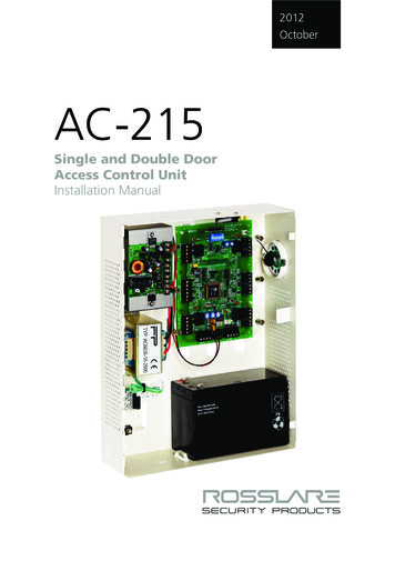
2012OctoberAC-215Single and Double DoorAccess Control UnitInstallation Manual
Copyright 2012 by Rosslare. All rights reserved.This manual and the information contained herein are proprietary to REL, RSP Inc. and/ortheir related companies and/or subsidiaries’ (hereafter:”ROSSLARE”). Only ROSSLAREand its customers have the right to use the information.No part of this manual may be re-produced or transmitted in any form or by any means,electronic or mechanical, for any purpose, without the express written permission ofROSSLARE.ROSSLARE owns patents and patent applications, trademarks, copyrights, or otherintellectual property rights covering the subject matter in this manual.TEXTS, IMAGES, AND ILLUSTRATIONS INCLUDING THEIR ARRANGEMENT IN THISDOCUMENT ARE SUBJECT TO THE PROTECTION OF COPYRIGHT LAWS AND OTHERLEGAL RIGHTS WORLDWIDE. THEIR USE, REPRODUCTION, AND TRANSMITTAL TO THIRDPARTIES WITHOUT EXPRESS WRITTEN PERMISSION MAY RESULT IN LEGALPROCEEDINGS.The furnishing of this manual to any party does not give that party or any third party anylicense to these patents, trademarks, copyrights or other intellectual property rights,except as expressly provided in any written agreement of ROSSLARE.ROSSLARE reserves the right to revise and change this document at any time, withoutbeing obliged to announce such revisions or changes beforehand or after the fact.
Table of ContentsTable of Contents1. Introduction to AC-215 ACU . 91.1Main Features . 111.1.1AC-215 . 111.1.2System . 111.1.3AC-215 Single and Double Door Access . 111.2Software. 122. Technical Specifications . 132.1Electrical Specifications . 132.1.1Main Unit. 132.1.2Outputs . 132.1.3Inputs . 132.1.4Indicators and Annunciators. 132.1.5Environmental Specifications . 132.1.6Mechanical Specifications . 133. Inputs and Outputs . 143.1Inputs . 143.1.1Release to Exit Button (REX) . 143.1.2Door Monitor . 143.1.3Tamper . 153.1.4General . 153.1.5Outputs . 153.1.6Door Lock . 153.1.7Door Alarm . 153.1.8Auxiliary . 163.1.9General . 163.1.10Card Readers. 163.1.11Keypad . 174. DIP Switch Settings Configuration . 184.1ACU Baud Rate. 184.2ACU Type . 19AC-215 Installation Manualiii
Table of Contents4.2.1Single Door Controller . 194.2.2Double Door Controller . 194.3ACU Addressing . 205. Communications . 225.1Serial Connection . 225.1.1RS-232 Connection . 225.1.2RS-485 Connection to the PC . 225.1.3Daisy Chain . 235.1.4Termination Resistors . 235.2Modem . 235.3Communication through the Local Area Network (LAN) . 246. Wiring . 256.1Inputs . 256.2Outputs . 256.2.1Power Supply . 266.3AC-215 Access Control Panel Diagram . 276.4Reader . 287. Accessories (Proximity Readers) . 297.1AY-C09, AY-D09 PIN Readers . 297.2AY-C11 / AY-D11 Prox Readers with Bell. 297.3AY-C11 / AY-D11 Prox Readers. 307.4AY-H12, AY-J12, AY-K12, AY-L12, AY-M12 Prox Readers . 307.5AY-C19 / AY-D19 PIN & Prox Readers . 317.6AY-L23 RF Reader . 31A. Connecting between MD-N32 and AC-215 . 32A.1Hardware Requirements. 32A.2Topics . 32A.3Connections – PC Side . 32A.4Connections – AC-215 Panel Side . 32A.5MD-N32 Configuration with AxTrax AS-525 . 32ivAC-215 Installation Manual
Table of ContentsB. Connecting between MD-N33 and AC-215 . 36B.1Hardware Requirements. 36B.2Topics . 36B.3Connections – PC Side . 36B.4Connections – AC-215 Panel Side . 36B.5MD-N33 Configuration with AxTrax AS-525 . 37B.6PC modem – configuration and initialization . 37B.7Remote modem – configuration and initialization. 39B.8Remote Modem Status . 40B.9Restoring factory default configuration . 41C. Power Supply Specifications . 42D. Limited Warranty . 43AC-215 Installation Manualv
List of FiguresList of FiguresFigure 1: AxTrax AS-525 and AC-215 System . 10Figure 2: Remote Site Modem Configuration . 23Figure 3: MD-N32 Configuration Connecting a Single Panel . 24Figure 4: Connecting Multiple Access Control Panels with MD-N32 . 24Figure 5: Wiring Four AC-215 Inputs . 25Figure 6: Door Lock – Fail Closed . 26Figure 7: Door Lock – Fail Open . 26Figure 8: AC-215 Wiring to Power Supply. 27Figure 9: AC-215 Wiring Communications. 27Figure 10: Reader Cable Coloring . 28viAC-215 Installation Manual
List of TablesList of TablesTable 1: DIP Switches and their Functions . 18Table 2: Switch Baud Rates. 18Table 3: Available Panel Addresses . 20Table 4: RS-232 Connection . 22AC-215 Installation Manualvii
Notice and DisclaimerNotice and DisclaimerThis manual’s sole purpose is to assist installers and/or users in the safe andefficient installation and usage of the system and/or product, and/or softwaredescribed herein.BEFORE ATTEMPTING TO INSTALL AND/OR USE THE SYSTEM, THE INSTALLER ANDTHE USER MUST READ THIS MANUAL AND BECOME FAMILIAR WITH ALL SAFETYREQUIREMENTS AND OPERATING PROCEDURES. viiiThe system must not be used for purposes other than those for which itwas designed.The use of the software associated with the system and/or product, ifapplicable, is subject to the terms of the license provided as part of thepurchase documents.ROSSLARE ENTERPRISES LIMITED and/or its related companies and/orsubsidiaries’ (hereafter:"ROSSLARE") exclusive warranty and liability islimited to the warranty and liability statement provided in an appendix atthe end of this document.This manual describes the maximum configuration of the system with themaximum number of functions, including future options. Therefore, notall functions described in this manual may be available in the specificsystem and/or product configuration you purchased.Incorrect operation or installation, or failure of the user to effectivelymaintain the system, relieves the manufacturer (and seller) from all or anyresponsibility for consequent noncompliance, damage, or injury.The text, images and graphics contained in the manual are for thepurpose of illustration and reference only.In no event shall manufacturer be liable for any special, direct, indirect,incidental, consequential, exemplary or punitive damages (including,without limitation, any and all damages from business interruption, loss ofprofits or revenue, cost of capital or loss of use of any property or capitalor injury).All graphics in this manual are for reference only, some deviation betweenthe image(s) and the actual product may occur.All wiring diagrams are intended for reference only, the photograph orgraphic of the PCB(s) are intended for clearer illustration andunderstanding of the product and may differ from the actual PCB(s).AC-215 Installation Manual
Introduction1.IntroductionThe AC-215 Access Control System and the AxTrax AS-525 PC software area combination that gives full control over the entrances of your premises. TheAxTrax AS-525 software supports control for both single and double doorentrances with which up to 255 AC-215 Access Control Units (ACUs) can bemonitored.The AC-215 employs the latest technology to meet the requirements of themarket. It controls one or two doors when used as a standalone controller, andup to 512 doors/256 networks and 5000 users when used as a networkedcontroller using the AxTrax AS-525 software.The AxTrax AS-525 software, which is user-friendly and intuitive, definessettings and event logs. A single server, communicating to and from the ACU,can serve unlimited network clients. The system’s database is saved in theserver. The database can be set to back up, and can import/export previousconfigurations. Clients are able to modify the database; for example, definenew employees and/or their access permissions.AxTrax AS-525 can run under Windows 98, 2000, NT or XP operatingsystems.Figure 1 is an example of how the AxTrax AS-525 and AC-215 system canbe set up.AC-215 Installation Manual9
IntroductionFigure 1: AxTrax AS-525 and AC-215 SystemAC-215Single DoorRS-485/232ConverterAxTrax RS232SoftwareRS485AC-215Single DoorRS485DoorMonitorAC-215Double DoorAC-215Up to 32 ACUsRS485MaglockExitbuttonReader,Keypad,and DoorReleaseDoor 1Door 22 readersforReader InandReaderOutReaderDoor 3Exit buttonReader, Keypad,and Door ReleaseDoor 410AC-215 Installation Manual
Introduction1.1Main Features1.1.1AC-215 Two In/Out readersFour inputsFour outputsOptional secure mode that requires card and PIN entryAntipassback real and time with forgive featureUp to 4 different site codes Automatic operation by time zone for every outputOptional first person delay before automatic door unlockingOptional expanded lock operation timeActivated auxiliary output by reader transactions or authorized usersDoor and panel alarms – door forced , door held open, door held openalert and tamper alarmProgrammable relock when opening/closing doorsMan trap door in double door configurationBuilt-in sounder generator for chime, bell and siren signals 1.1.2System Up to 256 access control unitsUp to 256 networks (with one controller per network)Up to 32 ACU in every network (64 doors in every network)Up to 5000 users with rights (up to 25000 users recorded)5000 log events64 holidays (copied from MS Outlook – option) 32 time zones128 access groups1.1.3AC-215 Single and Double Door AccessThe operation mode is first defined on the 8-Way DIP switch on the AC-215main PCB (the third switch defines the operation mode as described in Section4.2) and then defined as either single or double door using the AxTrax AS525 software; both definitions should be correlate.AC-215 Installation Manual11
Introduction1.1.3.1Single Door ControllerThis access type has two readers – In or OutOutputsInputsDoor lock strikeRelease to exitAuxiliary outputDoor monitor inputAlarm outputTamper inputGeneral purpose output General purpose input1.1.3.2Double Door ControllerThis access type has two readers – In or OutOutputsInputsDoor 1 lock strikeRelease to exit door1Door 1 alarm output Door 1 monitor inputDoor 2 lock strikeRelease to exit door 2Door 2 alarm output Door 2 monitor input1.2SoftwareThe AxTrax AS-525 software is user-friendly and intuitive. Its graphicinterface is used to define settings, which are downloaded to the ACU andevent logs which are uploaded to the PC to generate reports. A single server,which communicates to and from the ACU, can serve unlimited networkclients.The system’s database is saved in the server. The database can be set tobackup and can import/export previous configurations. Clients are able tomodify the database, for example, define new employees and their accesspermissions.The software enables features to be added as and when they are required. Themodular software enables the user interface to be as powerful and strong asrequired and yet remains simple to use. The software can be set for automaticbackup on a periodic basis.AxTrax AS-525 can be run on Windows 98, 2000, NT and XP.For UL installations, the installer must configure the system as fail-safe tocomply with NFPA (National Fire Protection Association) regulations.12AC-215 Installation Manual
Technical Specifications2.Technical SpecificationsThis chapter discusses the technical specification required for the system.2.1Electrical Specifications2.1.1Main UnitOperating Voltage12 VDC 0.5AFrom PS-14Maximum Input Current(not including attached devices)Standby: 125 mAMaximum: 325 mA2.1.2OutputsRelay Outputs2.1.3General Inputs:Reader's Electrical requirements:2.1.45 A Relay N.O. and N.C. optionsInputsHigh impedance active low inputs.Maximum voltage: 5 VDCVoltage: 12 VDCMax Current: 300 mAIndicators and AnnunciatorsVisual:8 on board LEDs as well as three PS LEDs (power,Low Battery, output (V) Fail)Audio:Built-in sounder (Bell, Chime and Siren)Speaker's ElectricalCharacteristics:8 Ohm, 250 mW2.1.5Environmental SpecificationsOperating Temperature:0 C to 49 C (32 F to 120.2 F)Operating Humidity:0 to 85% (non-condensing)2.1.6Mechanical SpecificationsEnclosure's Dimensions (LxWxD): 264 x 334 x 84.5 mm (10.4 x 13.2 x 3.4 in.)Weight:AC-215 Installation Manual3.77 kg (8.31 lbs)13
Inputs and Outputs3.Inputs and OutputsThis chapter discusses the AC-215 ACU input and output requirements.3.1Inputs3.1.1Release to Exit Button (REX)REX enables quick exit from a premises. The following should be defined:Single door controller:Door 1 – IN1Double door controller: Door 1 – IN 1Door 2 – IN 2Usually the REX input is connected to a push button that is located inside thepremises. The push button opens a door without reading a proximity card orPIN code.Generally, the REX is located in a convenient position such as near thereception area, and is always set as enabled in the AxTrax AS-525 software.3.1.2Door MonitorThe Door Monitor connects to a door’s micro switch for door statusmonitoring. The following should be defined:Single door controller:Door 1 – IN1ADouble door controller: Door 1 – IN 1ADoor 2 – IN 2ATwo alarm states can be generated: Forced alarm- When the door is forcibly opened by unauthorized persons Door held open alarm- When the door is open for a period exceeding thelock strike programmed open timeA Door held open alert can be generated by activating chime on speaker toremind that the door should be close.After the ACU enables access, the lock is activated according to itsprogrammed time until one of the following occurs: The ACU stops lock activation immediately after the door opens The ACU waits for the door to close. (This can help to reduce tailgating)When the door open time period expires the ACU ends lock activation.14AC-215 Installation Manual
Inputs and Outputs3.1.3TamperThe Tamper input connects to a tamper micro switch assembled within theACU panel.The following should be defined:Single door controllerDoor 1 – IN2Tamper input is activated when the panel is opened through vandalism. Thesystem has two additional tamper inputs on the reader terminals.3.1.4GeneralThe General input connects to any general-purpose dry contact input.Single door controllerDoor 1 – IN2AThis function can be used when activating the general-purpose outputconnections (for example, alarm sensors, monitoring power supply failure,etc.). The ACU reports activation if this input changes status.The system has four output relays. Their contacts are voltage free and rated 5Aat 12V AC or DC. This indicates that output is very versatile and can operatevirtually any electrical equipment including Fail Open and Fail Close locks,electric gates and so on.3.1.5OutputsWe recommend using a suppression diode for all outputs.3.1.6Door LockThere are two types of door locking devices: Fail open (fail secure) Fail close (fail safe) The user can select either normally open or normally closed output contacts.The following should be defined:Single door controllerDoor 1 – OUT1Double door controllerDoor 1 – OUT1Door 2 – OUT2The output can sink current from any power supply (see Appendix C). In a timezone door locking is activated in the following modes: Grant Access Automatic Relock3.1.7Door AlarmThis output is activated when either an alarm occurs in the system, orautomatically by a time zone. The following should be defined:AC-215 Installation Manual15
Inputs and OutputsSingle door controllerDoor 1 – OUT1ADouble door controllerDoor 1 – OUT1ADoor 2 – OUT2AThe output can be activated for a specified time and closes when the timerends.3.1.8AuxiliaryThis output is activated when a transaction occurs in the readers that are eitherassociated with auxiliary, or automatically by a time zone. The following shouldbe defined:Single door controllerDoor 1 – OUT2The output has two activations modes: Time – active for a specified time and closes when the timer ends Toggle – active for every change in the output trigger – the triggerchanges state3.1.9GeneralThis output is usually related to the general input or automatically by a timezone.The following should be defined:Single door controllerDoor 1 – OUT2AThe output has three activation modes: Follow input – output follows the input state Toggle – active for every change in the output trigger – the triggerchanges state Time – active for a specified time and closes when the timer ends3.1.10Card ReadersTwo card readers can be connected to the ACU. The following should bedefined:Single door controllerDoor 1 – Reader 1 IN/OUT/AuxiliaryReader 2 IN/OUT/auxiliaryDouble door controllerDoor 1 – Reader 1 IN/OUTDoor 2 – Reader 2 IN/OUTThe readers can be assigned to a single or double door controller’s door as anIN or OUT reader and can activate the auxiliary output in a single doorconfiguration.The reader’s tamper connects to the ACU and can generate an alarm. Thereader’s green LED input is activated by the ACU when in the Card and PINsecure mode to inform the user to enter his personal PIN number after enteringhis card.16AC-215 Installation Manual
Inputs and Outputs3.1.11KeypadTwo keypads can be alternatively connected to the ACU on Reader1 andReader2 terminals. The following should be defined:Single door controllerDoor 1 Keypad – Reader 1 IN/OUTKeypad – Reader 2 IN/OUTDouble door controllerDoor 1 Keypad – Reader 1 IN/OUTDoor 2 Keypad – Reader 2 IN/OUTThe keypad type must be a Rosslare format keypad.A keypad has to be connected for any reader mode that requires PIN codeentries, such as Card or PIN, PIN only or Card and PIN (Secured mode).AC-215 Installation Manual17
DIP Switch Settings Configuration4.DIP Switch Settings ConfigurationThe ACU Dipswitch controls a number of operating parameters including thedevice address and baud rates for serial communication.1 2 3 4 5 6 7 8Power down the ACU before making changes in the dipswitch settings.Restart the ACU after modifications are made. The new settings areautomatically defined after power up.The following is a list of dipswitch numbers and their functions:Table 1: DIP Switches and their Functions4.1DIP SwitchFunction1-2Set ACU baud rate3Sets ACU type (single door or double door controller)4-8Set ACU addressACU Baud RateThe ACU serial port baud rate, set in dipswitches one and two, defines thecommunication speed for connecting with a PC in a network connection.1 2 3 4 5 6 7 8The following lists switch 1 and 2 status and baud rate:Table 2: Switch Baud RatesSwitch 2 Baud Rate Switch 1 Switch 2 Baud RateOffOff9600OnOff38400OffOn19200OnOn57600 The ACU baud rate must be identical to the host PC’s serial port baud rate.18AC-215 Installation Manual
DIP Switch Settings Configuration4.2ACU TypeThe ACU type is defined using the third DIP switch. Both the single and doublecan be set.1 2 3 4 5 6 7 8 Off – defines single door controls On – defines a double door controls4.2.1Single Door ControllerThis access type has two readers, IN and OUT, as follows: Outputs: Door lock strike Auxiliary output Alarm output General purpose output Inputs: Release to exit Door monitor input Tamper input General purpose inputFor more information, see Chapter 3.4.2.2Double Door ControllerThis access type has two readers, IN and OUT, as follows: Outputs Door 1 lock strike Door 1 alarm output Door 2 lock strike Door 2 alarm outputInputs Release to exit door1 Door 1 monitor input Release to exit door 2 Door 2 monitor inputAC-215 Installation Manual19
DIP Switch Settings Configuration4.3ACU AddressingThe DIP switch is used to select the binary coded ACU address.1 2 3 4 5 6 7 8 The ACU address is defined in the AxTrax AS-525 software. For successfulcommunications, the dipswitch must be defined with the same address.Table 3 displays the 32 address settings available:Table 3: Available Panel AddressesAddressSwitch 4Switch 5Switch 6Switch 7Switch OnOnOffOffOff26OnOnOffOffOn20AC-215 Installation Manual
DIP Switch Settings ConfigurationAddressSwitch 4Switch 5Switch 6Switch OffOn31OnOnOnOnOff32OnOnOnOnOnAC-215 Installation ManualSwitch 821
Communications5.CommunicationsCommunication lines are used to upload and download information betweenthe ACU and the AxTrax AS-525 software. Communication between theACU and PC is displayed by the system’s two LEDs. The RX LED flashes when the controller receives data The TX LED flashes when the controller transmits data The ACU address is defined in the AxTrax AS-525 software. For successfulcommunications, the dipswitch must be defined with the same address.There are three connection modes: Serial RS232 RS485 Modem LAN5.1Serial ConnectionThe PC Serial Port controlling the ACU is assigned in the Network Properties inthe AxTrax AS-525 software. By default the default is set to 9600 for directconnection to the PC using the standard RS-232 interface.5.1.1RS-232 ConnectionTable 4: RS-232 ConnectionACUDB9 ConnectorDB25 ConnectorGNDTxRxDTRPin 5Pin 2Pin 3Pin 4Pin 7Pin 3Pin 2Pin 20The RS232 connection can only be used for one ACU. The distance betweenthe PC and ACU can be no more than 150 feet (50 meters). If the baud rate isincreased to 57600 the distance can be up to 30 feet (10 meters). J1 must bein the RS232 position to select the RS232 communication.5.1.2RS-485 Connection to the PCUp to 32 ACUs can be linked together and connected to a singlecommunication port on the PC.The RS485 interface must be used when multiple controllers are connected.The serial port used to control the ACU is assigned in the AxTrax AS-525software Network Properties dialog box.22AC-215 Installation Manual
CommunicationsACU supports the two-wire RS485 interface. RS485 interface enables thedistance between the ACU and PC to be extended up to 4000 feet (1300)meters. The data line wiring must be in daisy chain formatting with one controlunit following another. The first ACU connecting to the PC must use the MD14, RS485 to RS232 adaptor.5.1.3Daisy ChainCommunication lines must be wired in a daisy chain format with one ACUfollowing another. J1 must be in the RS485 position.5.1.4Termination ResistorsAt each end of the data line a termination resistor of 130 Ohm is requiredacross the L1 and L2 connections.5.2ModemThe PC modem connection, used to control the ACU, is assigned in theAxTrax AS-525 software’s Network Properties dialog box.The modem is used when the distance between the ACU and the PC is greaterthan the recommended serial connection distance or in an application wherean alternative RS232/RS485 network is unavailable.Figure 2 illustrates remote site modem configuration with AC-215.Figure 2: Remote Site Modem ConfigurationFor more information, see Appendix B.AC-215 Installation Manual23
Communications5.3Communication through the Local Area Network (LAN)The TCP/IP connection, used to control the ACU, is assigned in the AxTrax AS-525 software’s Network Properties dialog box.The PC running the AxTrax AS-525 software can communicate with the ACUthrough the LAN card inside the PC. The ACU connects to the LAN usingRosslare MD-N32, TCP/IP to RS232 gateway converter. MD-N32 can beconnected in any legal network address in the Local Area Network.The following type of connection is used when a LAN network already existsand therefore the long RS485 network is not required. This schematicillustrates the connection of a single AC-215 to the PC using the LAN network.MD-N32 must be first configured by Rosslare's Netconfig software. The settingis stored in a non-volatile memory in the MD-N32.Figure 3: MD-N32 Configuration Connecting a Single PanelMultiple ACUs can be connected by adding an RS485 converter (MD-14)between the RS485 ACUs network and MD-N32 converter.Figure 4: Connecting Multiple Access Control Panels with MD-N32For more information, see Appendix A.24AC-215 Installation Manual
Wiring6.Wiring6.1InputsFigure 5 illustrates wiring for four AC-215 inputs. For further details, seeChapter 3.Figure 5: Wiring Four AC-215 Inputs6.2OutputsFigure 6 and Figure 7 illustrate wiring for two main types of 12VDC electricrelease mechanisms. Other electrical devices can be switched using the voltagefree relay contacts.AC-215 Installation Manual25
WiringFigure 6: Door Lock – Fail ClosedFigure 7: Door Lock – Fail Open6.2.1Power SupplyFigure 8 illu
Only ROSSLARE and its customers have the right to use the information. No part of this manual may be re-produced or transmitted in any form or by any means, electronic or mechanical, for any purpose, without the express written permission of ROSSLARE. ROSSLARE owns patents and patent applications, trademarks, copyrights, or other