Transcription
Installing AxtraxNGCreating Networks and FindingPanelsTechnical Support EngineeringRosslare Security NAFor more information please seewww.axtraxng.com
This document will guide you through creating a networkand “finding” or connecting to an access control panel. The first example will be for a simple 1 panel serial networkutilizing the MD14 (U) cable directly from the PC to thepanel. The MD14 (U) cable provides an RS-232 to RS-485 interfaceadapter in a cable form, the MD14U version combines aUSB to serial adapter and the RS485 converter hardware allinto a single cable assembly. The MD14(U) connects directly to the panel on the smallwhite 4 pin connector labeled MD14. Insure the RS-232/RS-485 switch is in the RS-485 position.
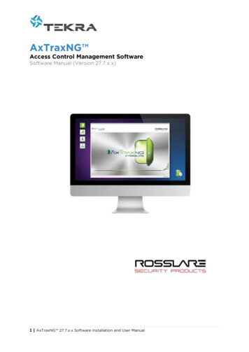
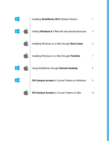
Network Connections and IndicatorsAC-215IP, AC225U/IP, AC-425U/IPAC-215UEthernet Port(not in use on U)RDR 2 RDR 1LED 3LINKLED 4CONNECTEDRS-232RS-485TX RXTX RXMD-14RS-232TX RX (-) DTRRS-485 - L1 L2TX RX (-) DTR - L1 L2RS-232RS-485MD-14RS-232RS-485
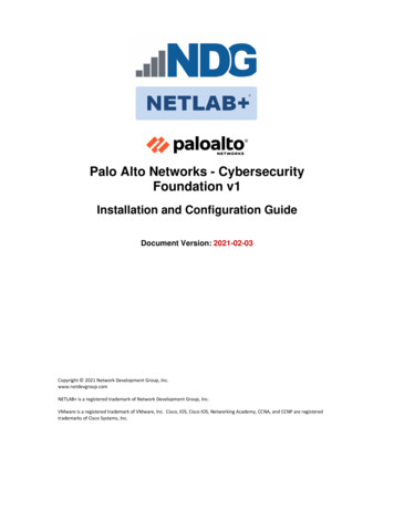
Click the sign to the left of AxTraxNG toexpand the menu. Highlight AC Networks
Open the Windows Device Manager. Expand Ports (Com & LPT)
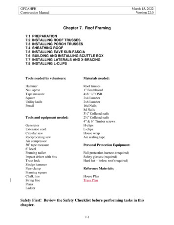
Click the Green to create new network Enter the number of the COM port Leave the speed at 9600, check switches on ACpanel Click OK
You should now have “Network 1” under ACNetworks. Status should be OK, if it goes to“disconnected” or “network problem” checkCOM port settings and driver status.
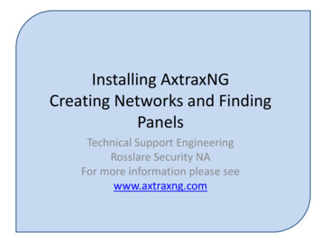
Highlight Network 1. Click the “Find Panels” icon. Click the button labeled Find Panels.
In a few seconds the panel should appear inthe list. If no panel appears after select Find Panels asecond time. When the panel appears select Stop Find
Check the box on each panel or click Select All. Click Add Panels to add all of the panels to thenetwork.
The panel status should come up Initialized,the download count will show 3 to 9 for aminute or longer while the panel initializes.
The panel status should change to connectedwithin 2 minutes. If not or if the message initialization failedcomes up there is a communications problem.Typically this is not an issue on simple serialnetworks.
Trouble Shooting Issues with Finding PanelsIf Find Panels fails do the following;1. Try to find the panel again, up to three times.2. Set the baud rate to 9600 (If not already),1. Insure the dipswitches are set to 9600 as well as the network configurationin AxtraxNG.3. Observe the panel while trying to find it;1. Is the RX LED flashing every 2 to 3 seconds?1. If not,1. check the MD14U cable connection,2. check the position of the RS232/RS485 switch, switch it back andforth twice leaving it in the RS485 position and try to find again.4. Close AxtraxNG client, restart the PC, power cycle the panel and try to find thepanel again , up to three times.5. Move the MD14U (or serial adapter) to another USB port.6. Go into Device Manager and find the new COM port, change the network settingin AxtraxNG to the new COM port and try to find the panel again, three times ifrequired.7. If all of these steps fail please contact Rosslare Tech Support for further help.
Firmware UpdateThe next step is to update the firmware in the panel. The firmwaremust match the software being used, each version of softwarecontains the correct firmware files for all panels supported by thatversion of software.When installing a new panel into an older system you will need toperform the firmware update to “roll back” the firmware in the panelto match the software, using mismatched firmware/software can andwill result in abnormal behavior.AxtraxNG will select the correct firmware file for the panel typebeing updated. If the type identified does not match the actualpanel then delete the panel from the network and repeat the findpanel operation. If it still misidentifies the panel contact techsupport.
Select Panel 1 on the left Select the “Update Firmware” icon at the topas shown. Insure the panel type is correct and click OK tostart the firmware update.
If you receive the above message you may skipupdating the firmware if the panel is new out of thebox.If the panel has been used in another system orconfiguration, it is advisable to do the firmwareupdate to clear all memory and reset the panel tofactory defaults before continuing.
Select OK to begin the firmware download.The download count will show the progress as thefirmware is downloaded. When it reaches 0 thefirmware update is complete.The progress bar at the bottom also shows thefirmware update status.
Trouble Shooting Firmware Update IssuesIf the firmware update fails do the following;1. Try to update the firmware again.2. Set the baud rate to 9600 (If not already).3. Close AxtraxNG client and restart the PC, power cycle thepanel and try to update firmware again.4. Move the MD14U (or serial adapter) to another USB port.5. Go into Device Manager and find the new COM port, changethe network setting in AxtraxNG to the new COM port andretry the firmware download.6. If all of these steps fail please contact Rosslare Tech Supportfor further help.
Once the firmware update completes, the progressbar will go away, the download count will go to 0briefly then go to something in the range of 3 to 9while the panel resets.Once the panel reinitializes you will see thedownload count go to something in the range of 50to 60 and count down to 0.When it reaches 0 again the panel is ready toproceed.
The second example is for a TCP/IP network . In this scenario we will createa TCP/IP network with 2 panels, one connected to the LAN and the secondconnected via RS-485.The steps are;1. Create the TCP/IP network2. Find both panels.3. Update Firmware
Click the on AC Networks.Click the green to create a new network.Select Network Type TCP/IP.Click the Configuration button.
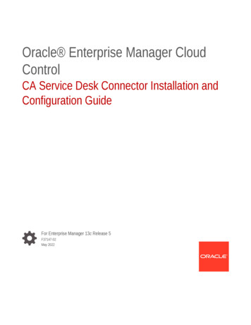
The AxtraxNG software will search the localnetwork (local subnet) for MAC addresses thatbelong to Rosslare products and list them inthe box as shown. Select the MAC address of the panel from thelist.
Refer to the previous slide, on the Network Configuration screen check orcomplete the following items;1. Gateway Type; should be MD-IP32 Onboard for IP panels, MD-N32 for theMD-N32 serial to ethernet gateway.2. Serial Speed; set to match the dipswitch setting on the panel, 9600 isrecommended for the most reliable operation.3. Local IP Address; If the customer IT department has provided an IPaddress input it here.4. Subnet; enter the subnet mask provided by the customer, usually255.255.255.0.5. Gateway; Enter the gateway address for the local LAN, this should havebeen provided by the IT department, it can also be determined by runningipconfig.exe on the PC.6. Local Port; leave at the default of 1000.7. Click Apply to program the network interface.8. Click OK to save the information, this will go back to the NetworkProperties screen, click OK again to create the network.9. The network status should now show connected. If utilizing an AC-215IPor AC-225 panel the connected LED should now come on in a few seconds.
Network Status should indicate OK, if NetworkProblem or Disconnected is displayed thenetwork configuration is not correct.
If the customer has not provided an IP address a relatively safe IP addressmay be determined as follows;Open a command prompt in windows and run “ipconfig”.The IP address of the PC, subnet mask and local gateway address are listedas shown.
The IP address should be in the same subnet (192.168.1.xxx) as the PCunless the network is a remote configuration which will be discussed later.If no IP address has been provided a relatively safe address can bedetermined by taking the IP address of the PC being used and adding 10 tothe last portion of the address, (192.168.1.11 plus 10 would give192.168.1.21). You should check the new address by pinging it beforeprogramming the panel to insure no other device responds, from acommand prompt in windows, type “ping 192.168.1.21” without the quotes,you should receive a message “Destination Host Unreachable”.
If the ping results in a reply, add 10 to the IP address try again. The lastoctet or last 3 digits of the IP address must be in the range of 2 to 249, thenetwork interface of the panel will not function at addresses over 249.Complete the network configuration as follows;1. Gateway; Enter the gateway address for the local LAN, this should havebeen provided by the IT department, it can also be determined by runningipconfig.exe on the PC.2. Local Port; leave at the default of 1000.3. Click Apply to program the network interface.4. Click OK to save the information, this will go back to the NetworkProperties screen, click OK again to create the network.5. The network status should now show connected. If utilizing an AC-215IPor AC-225 panel the connected LED should now come on in a few seconds.
Trouble Shooting Network Configuration issuesIf the network status displays “Network Problem” or Disconnected” there is a problemwith the network configuration. This may be in the steps just performed, a firewall orintrusion detection system on the LAN blocking traffic, a misconfigured switch orrouter or a problem with panel itself.1. Run ipconfig again and compare the output to the settings in the networkconfiguration screen once again. Insure that not only is the IP address setcorrectly but also that the subnet and gateway match the PC.2. If the address was provided by the customer, power down the panel and ping theIP address to insure no other device is at the same IP address, you should get themessage “Destination Host Unreachable” . If a reply is received then anotherdevice is using the address and either it needs to be changed or the IP address ofthe panel does, consult the customer if in doubt.3. Rarely does the Windows firewall on the PC affect the network however thirdparty security packages may. Consult the customer to see if they can temporarilyany third party security software to see if it is the cause of the problem.4. Another frequent cause of problems is port security on managed switches orrouters blocking traffic, have the LAN administrator insure there is no portsecurity enabled on the panels network port.
Highlight Network 1. Click the “Find Panels” icon. Click the button labeled Find Panels.
In a few seconds the panel(s) should appear inthe list. If no panel appears after select Find Panels asecond time. When the panel appears select Stop Find
Check the box on each panel or click Select All. Click Add Panels to add all of the panels to thenetwork.
The panel status should come up Initialized,the download count will show 3 to 9 for aminute or longer while the panel initializes.
The panel status should change to connectedwithin 2 minutes. If not or if the message initialization failedcomes up there is a communications problem.Typically this is not an issue on simple serialnetworks.
Trouble Shooting Issues with Finding PanelsIf Find Panels fails do the following;1. Try to find the panel again, up to three times.2. Set the baud rate to 9600 (If not already),1. Insure the dipswitches are set to 9600 as well as the network configuration inAxtraxNG.3. Observe the panel while trying to find it; Is the RX LED flashing every 2 to 3 seconds, if not;1. Check the position of the RS232/RS485 switch, switch it back and forth twice leavingit in the RS485 position and try to find again.2. Close AxtraxNG client, restart the PC, power cycle the panel and try to find the panelagain , up to three times.3. Try to PING the panel, if the Ping fails troubleshoot the network configuration.4. If the RX LED is flashing do the following;1. Go back to the network configuration, change the port from the default 1000 to 2000,click apply, then OK and OK again to save the changes, try to find the panel again.2. Go back to the network configuration screen again, this time change the baud rate to115200, click apply, then OK and OK to save the changes. Power down the panel,move dipswitch 1 to the up or ON position, power the panel back up, try to find again.3. (AC 215IP or 225IP only) are the RDR1 & 2 LEDs in the top right on solid, if not try toflash firmware again.5. If all of these steps fail please contact Rosslare Tech Support for further help.
Optionally, you may now customize the namesof the Doors and Readers and the Networksand Panels if desired. To change the name of the doors, navigate asshown to the doors tab under the panel. Double click in the name field and edit thename.
To change the name of the readers, navigateas shown to the Readers tab under the panel. Double click in the name field and edit thename. If the panel is configured for 2 readers perdoor label one as in the other as out. If any readers are PIN only or PIN and PROX asshown, change the Operation mode to Card orPIN Set the Keypad type to Wiegand 6 Rosslare. Click OK when done.
If all of these steps fail please contact Rosslare Tech Support for further help. Firmware Update The next step is to update the firmware in the panel. The firmware . If it still misidentifies the panel contact tech support. Select Panel 1 on the left Select the "Update Firmware" icon at the top as shown.