Transcription
Wireless Networking TechnologiesWLAN, WiFi Mesh and WiMAXSridhar IyerK R School of Information TechnologyIIT Bombaysri@it.iitb.ac.inhttp://www.it.iitb.ac.in/ sri
Course Outline Wireless Networks– Difference from wired– Mobility RF Basics– Frequency, modulation– Medium access control Wireless LANs (WiFi)– 802.11 standards– Mobility support– Voice and QoS support Mesh and Adhoc Networks– Routing and Transport WiFi Overview Wireless MANs (WiMaX) WiMaX Overview Trends– Basic elements– Standards and variants– Basic elementsSridhar Iyer– 802.16 standard– Voice and QoS support– Overlay networksIIT Bombay2
Wireless Networks
Wireless networks Access computing/communication services, on the move Wireless WANs– Cellular Networks: GSM, GPRS, CDMA– Satellite Networks: Iridium Wireless LANs– WiFi Networks: 802.11– Personal Area Networks: Bluetooth Wireless MANs– WiMaX Networks: 802.16– Mesh Networks: Multi hop WiFi– Adhoc Networks: useful when infrastructure not availableSridhar IyerIIT Bombay4
Limitations of the mobile environment Limitations of the Wireless Network limited communication bandwidth frequent disconnections heterogeneity of fragmented networks Limitations Imposed by Mobility route breakages lack of mobility awareness by system/applications Limitations of the Mobile Device short battery lifetime limited capacitiesSridhar IyerIIT Bombay5
Mobile communication Wireless vs. mobile Examplesstationary computerlaptop in a hotel (portable)wireless LAN in historic buildingsPersonal Digital Assistant (PDA) Integration of wireless into existing fixed networks:– Local area networks: IEEE 802.11, ETSI (HIPERLAN)– Wide area networks: Cellular 3G, IEEE 802.16– Internet: Mobile IP extensionSridhar IyerIIT Bombay
Wireless v/s Wired networks Regulations of frequencies– Limited availability, coordination is required– useful frequencies are almost all occupied Bandwidth and delays– Low transmission rates few Kbits/s to some Mbit/s.– Higher delays several hundred milliseconds– Higher loss rates susceptible to interference, e.g., engines, lightning Always shared medium– Lower security, simpler active attacking– radio interface accessible for everyone– secure access mechanismsimportantSridhar IyerIIT Bombay7
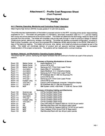
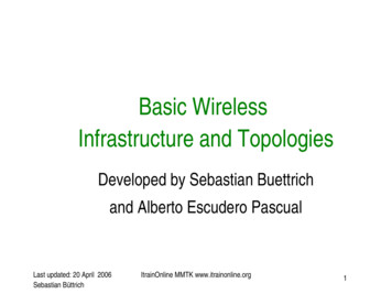
Wireless Technology Landscape72 Mbps54 MbpsTurbo .11a802.11{a,b}5 11 Mbps802.11b1 2 Mbps802.11Bluetoothµwave p to p links3GWCDMA, CDMA2000384 Kbps2GIS 95, GSM, CDMA56 KbpsSridhar Iyer.11 p to p linkIndoorOutdoorMid rangeoutdoorLong rangeoutdoorLong distancecom.10 – 30m50 – 200m200m – 4Km5Km – 20Km20m – 50KmIIT Bombay8
Reference rkNetworkNetworkNetworkData LinkData LinkData LinkData dhar IyerIIT Bombay9
Effect of mobility on protocol stack Application– new applications and adaptations– service location, multimedia Transport– congestion and flow control– quality of service Network– addressing and routing– device location, hand over Link– media access and security Physical– transmission errors and interferenceSridhar IyerIIT Bombay10
Perspectives Network designers: Concerned with cost effectivedesign– Need to ensure that network resources are efficiently utilizedand fairly allocated to different users. Network users: Concerned with application services– Need guarantees that each message sent will be deliveredwithout error within a certain amount of time. Network providers: Concerned with systemadministration– Need mechanisms for security, management, fault toleranceand accounting.Sridhar IyerIIT Bombay11
RF Basics
Factors affecting wireless system design Frequency allocations– What range to operate? May need licenses. Multiple access mechanism– How do users share the medium without interfering? Antennas and propagation– What distances? Possible channel errors introduced. Signals encoding– How to improve the data rate? Error correction– How to ensure that bandwidth is not wasted?Sridhar IyerIIT Bombay13
Frequencies for communicationtwistedpaircoax cable1 Mm300 Hz10 km30 kHzVLF LFoptical transmission100 m3 MHzMFHF1m300 MHzVHFUHF10 mm30 GHzSHFEHF100µ m3 THzinfrared1µ m300 THzvisible light UVVLF Very Low Frequency UHF Ultra High FrequencyLF Low Frequency SHF Super High FrequencyMF Medium FrequencyEHF Extra High FrequencyHF High FrequencyUV Ultraviolet LightVHF Very High Frequency Frequency and wave length: λ c/f wave length λ , speed of light c 3x10⁸m/s, frequency fSridhar IyerIIT Bombay14
Wireless frequency allocation Radio frequencies range from 9KHz to 400GHZ (ITU) Microwave frequency range––––1 GHz to 40 GHzDirectional beams possibleSuitable for point to point transmissionUsed for satellite communications Radio frequency range– 30 MHz to 1 GHz– Suitable for omnidirectional applications Infrared frequency range– Roughly, 3x10¹¹ to 2x10¹⁴ Hz– Useful in local point to point multipoint applications within confinedareasSridhar IyerIIT Bombay15
Frequencies for mobile communication VHF /UHF ranges for mobile radio– simple, small antenna for cars– deterministic propagation characteristics, reliable connections SHF and higher for directed radio links, satellitecommunication– small antenna, focusing– large bandwidth available Wireless LANs use frequencies in UHF to SHF spectrum– some systems planned up to EHF– limitations due to absorption by water and oxygen molecules(resonance frequencies) weather dependent fading, signal loss caused by heavyrainfall etc.Sridhar IyerIIT Bombay16
Frequency regulations Frequencies from 9KHz to 300 MHZ in high demand(especially VHF: 30 300MHZ) Two unlicensed bands– Industrial, Science, and Medicine (ISM): 2.4 GHz– Unlicensed National Information Infrastructure (UNII): 5.2 GHz Different agencies license and regulate––––www.fcc.gov USwww.etsi.org Europewww.wpc.dot.gov.in Indiawww.itu.org International co ordination Regional, national, and international issues Procedures for military, emergency, air traffic control, etcSridhar IyerIIT Bombay17
Wireless transmissionAntennaAntennaTransmitterReceiver Wireless communication systems consist of:– Transmitters– Antennas: radiates electromagnetic energy into air– Receivers In some cases, transmitters and receivers areon same device, called transceivers.Sridhar IyerIIT Bombay18
ilterAmplifierTransmitterSuppose you want to generate a signal that is sent at 900 MHz andthe original source generates a signal at 300 MHz. Amplifier strengthens the initial signal Oscillator creates a carrier wave of 600 MHz Mixer combines signal with oscillator and produces 900 MHz(also does modulation, etc) Filter selects correct frequency Amplifier Strengthens the signal before sending itSridhar IyerIIT Bombay19
Antennas
Antennas An antenna is an electrical conductor or system ofconductors to send/receive RF signals– Transmission radiates electromagnetic energy into space– Reception collects electromagnetic energy from space In two way communication, the same antenna can beused for transmission and receptionOmnidirectional Antenna(lower frequency)Sridhar IyerIIT BombayDirectional Antenna(higher frequency)21
Antennas: isotropic radiator Radiation and reception of electromagnetic waves,coupling of wires to space for radio transmission Isotropic radiator: equal radiation in all directions(three dimensional) only a theoretical referenceantenna Real antennas always have directive effects (verticallyand/or horizontally) Radiation pattern: measurement of radiation around anantennayzzyxSridhar IyerIIT Bombayxidealisotropicradiator22
Antennas: simple dipoles Real antennas are not isotropic radiators– dipoles with lengths λ /4 on car roofs or λ /2 (Hertzian dipole) shape of antenna proportional to wavelength Gain: maximum power in the direction of the main lobecompared to the power of an isotropic radiator (with thesame average power)λ /4yλ /2yzxside view (xy plane)Sridhar Iyerzside view (yz plane)IIT Bombayxsimpledipoletop view (xz plane)23
Antennas: directed and sectorized Often used for microwave connections or base stationsfor mobile phones (e.g., radio coverage of a valley)yyzxzside view (xy plane)xside view (yz plane)top view (xz plane)zzxxtop view, 3 sectorSridhar Iyerdirectedantennasectorizedantennatop view, 6 sectorIIT Bombay24
Antenna modelsIn Omni Mode: Nodes receive signals with gain GoIn Directional Mode: Capable of beamforming in specified direction Directional Gain Gd (Gd Go)Sridhar IyerIIT Bombay25
Directional communicationReceived Power (Transmit power)*(Tx Gain) * (Rx Gain)Directional gain is higherDirectional antennas useful for: Increase “range”, keeping transmit power constant Reduce transmit power, keeping range comparablewith omni modeSridhar IyerIIT Bombay26
Comparison of omni and directionalIssuesOmniDirectionalSpatial ectionalCost & ComplexityLowHighSridhar IyerIIT Bombay27
Antennas: diversity Grouping of 2 or more antennas– multi element antenna arrays Antenna diversity– switched diversity, selection diversity receiver chooses antenna with largest output– diversity combining combine output power to produce gain cophasing needed to avoid cancellationλ /4λ /2 Sridhar Iyerground planeIIT Bombayλ /4λ /2λ /2λ /2 28
Signal Propagation and Modulation
Signals physical representation of data function of time and location signal parameters: parameters representing the value ofdata classification––––continuous time/discrete timecontinuous values/discrete valuesanalog signal continuous time and continuous valuesdigital signal discrete time and discrete values signal parameters of periodic signals:period T, frequency f 1/T, amplitude A, phase shift ϕ– sine wave as special periodic signal for a carrier:s(t) At sin(2 π ft t ϕ t)Sridhar IyerIIT Bombay30
Signal propagation ranges Transmission range– communication possible– low error rate Detection rangesender– detection of the signalpossible– no communicationpossibletransmissiondistancedetection Interference rangeinterference– signal may not bedetected– signal adds to thebackground noiseSridhar IyerIIT Bombay31
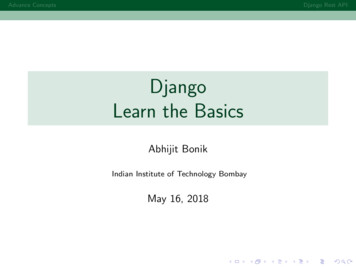
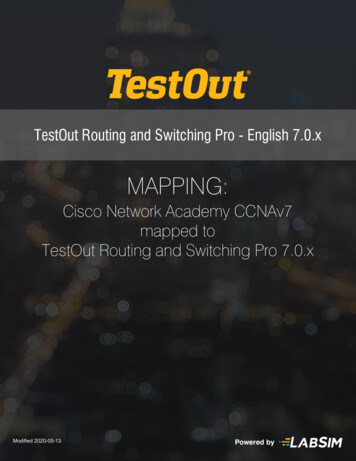
Attenuation: Propagation & RangeSridhar IyerIIT Bombay32
Attenuation Strength of signal falls off with distance overtransmission medium Attenuation factors for unguided media:– Received signal must have sufficient strength so thatcircuitry in the receiver can interpret the signal– Signal must maintain a level sufficiently higher thannoise to be received without error– Attenuation is greater at higher frequencies, causingdistortion Approach: amplifiers that strengthen higherfrequenciesSridhar IyerIIT Bombay33
Signal propagation Propagation in free space always like light (straight line) Receiving power proportional to 1/d²(d distance between sender and receiver) Receiving power additionally influenced by––––––fading (frequency dependent)shadowingreflection at large obstaclesrefraction depending on the density of a mediumscattering at small obstaclesdiffraction at edgesshadowingSridhar IyerreflectionrefractionIIT Bombayscatteringdiffraction34
Multipath propagation Signal can take many different paths between sender and receiver due toreflection, scattering, diffractionmultipathLOS pulses pulses Timedispersion:signalat sender signal is dispersed over timesignal at receiver interference with “neighbor” symbols, Inter Symbol Interference(ISI) The signal reaches a receiver directly and phase shifted distorted signal depending on the phases of the different partsSridhar IyerIIT Bombay35
Effects of mobility Channel characteristics change over time and location– signal paths change– different delay variations of different signal parts– different phases of signal partsquick changes in the power receivedpower(short term fading) long termfading Additional changes in– distance to sender– obstacles further awayshort term fadingtslow changes in the average powerreceived (long term fading) Sridhar IyerIIT Bombay36
Propagation modesTransmissionAntennaa) Ground Wave gnalb) Sky Wave PropagationEarthSignalc) Line of Sight PropagationEarthSridhar IyerIIT Bombay37
Modulation Digital modulation– digital data is translated into an analog signal (baseband)– ASK, FSK, PSK– differences in spectral efficiency, power efficiency, robustness Analog modulation– shifts center frequency of baseband signal up to the radiocarrier Motivation– smaller antennas (e.g., λ /4)– Frequency Division Multiplexing– medium characteristics Basic schemes– Amplitude Modulation (AM)– Frequency Modulation (FM)– Phase Modulation (PM)Sridhar IyerIIT Bombay38
Modulation and nalogbasebandsignalanalogmodulationradio 1001radio receiverradiocarrierSridhar IyerIIT Bombay39
Digital modulation Modulation of digital signals known as Shift Keying1 Amplitude Shift Keying (ASK):01– very simple– low bandwidth requirements– very susceptible to interference Frequency Shift Keying (FSK):– needs larger bandwidtht101t Phase Shift Keying (PSK):– more complex– robust against interference101 Many advanced variantstSridhar IyerIIT Bombay40
Multiplexing Mechanisms
Multiplexingchannels kik1k2k3k4k5k6c Multiplexing in 4 dimensionst– space (si)ct– time (t)– frequency (f)– code (c)s1fs2fct Goal: multiple useof a shared mediums3f Important: guard spaces needed!Sridhar IyerIIT Bombay42
Frequency multiplexSeparation of the whole spectrum into smaller frequency bandsA channel gets a certain band of the spectrum for the whole timeAdvantages:no dynamic coordinationnecessaryk1k2k3k4k5k6 works also for analog signals c Disadvantages: waste of bandwidthif the traffic isdistributed unevenly inflexible guard spacesftSridhar IyerIIT Bombay43
Time multiplex A channel gets the whole spectrum for a certainamount of time Advantages: only one carrier in themedium at any time throughput high evenfor many usersk1k2k3k4k5k6cf Disadvantages: precisesynchronizationnecessary tSridhar IyerIIT Bombay44
Time and frequency multiplex Combination of both methods A channel gets a certain frequency band for a certain amountof timek1k2k3k4k5k6 Example: GSM Advantages:c– better protection againsttapping– protection against frequencyselective interference– higher data rates compared tocode multiplexf but: precise coordinationtrequiredSridhar IyerIIT Bombay45
Code multiplex Each channel has a unique codek All channels use the samespectrum at the same time Advantages:1k2k3k4k5k6c– bandwidth efficient– no coordination and synchronizationnecessary– good protection against interferenceand tappingf Disadvantages:– lower user data rates– more complex signal regeneration Implemented using spreadspectrum technologySridhar IyerIIT Bombayt46
CDMA Example– D rate of data signal– Break each bit into k chips Chips are a user specific fixed pattern– Chip data rate of new channel kD If k 6 and code is a sequence of 1s and 1s– For a ‘1’ bit, A sends code as chip pattern c1, c2, c3, c4, c5, c6 – For a ‘0’ bit, A sends complement of code c1, c2, c3, c4, c5, c6 Receiver knows sender’s code and performs electronicdecode functionSu ( d ) d1 c1 d 2 c 2 d 3 c3 d 4 c 4 d 5 c5 d 6 c6 d1, d2, d3, d4, d5, d6 received chip pattern c1, c2, c3, c4, c5, c6 sender’s codeSridhar IyerIIT Bombay47
CDMA Example User A code 1, –1, –1, 1, –1, 1 – To send a 1 bit 1, –1, –1, 1, –1, 1 – To send a 0 bit –1, 1, 1, –1, 1, –1 User B code 1, 1, –1, – 1, 1, 1 – To send a 1 bit 1, 1, –1, –1, 1, 1 Receiver receiving with A’s code– (A’s code) x (received chip pattern) User A ‘1’ bit: 6 1 User A ‘0’ bit: 6 0 User B ‘1’ bit: 0 unwanted signal ignoredSridhar IyerIIT Bombay48
Spread spectrum technology Problem of radio transmission: frequency dependentfading can wipe out narrow band signals for duration ofthe interference Solution: spread the narrow band signal into a broadband signal using a special code protection againstnarrow band ction atreceiverfsignalspreadinterferencef Side effects:– coexistence of several signals without dynamic coordination– tap proof Alternatives: Direct Sequence, Frequency HoppingSridhar IyerIIT Bombay49
Spread spectrum communicationsSridhar IyerIIT Bombay50Source: Intersil
Effects of spreading and interferencedP/dfdP/dfi)user signalbroadband interferencenarrowband ar Iyerfv)freceiverIIT Bombayf51
DSSS propertiesSridhar IyerIIT Bombay52Source: Intersil
DSSS (Direct Sequence) XOR of the signal with pseudo random number(chipping sequence)– many chips per bit (e.g., 128) result in higher bandwidth of thesignaltb Advantages– reduces frequency selectivefading– in cellular networks base stations can use thesame frequency range several base stations candetect and recover the signal soft handover Disadvantages– precise power control necessarySridhar IyerIIT Bombayuser data01XORtcchippingsequence01101010110101 resultingsignal01101011001010tb: bit periodtc: chip period53
DSSS Transmit/Receivespreadspectrumsignaluser rSridhar IyerIIT Bombay54
Frequency Hopping SpreadSpectrum (FHSS) Signal is broadcast over seemingly random series of radiofrequencies Signal hops from frequency to frequency at fixed intervals Channel sequence dictated by spreading code Receiver, hopping between frequencies in synchronizationwith transmitter, picks up message Advantages– Eavesdroppers hear only unintelligible blips– Attempts to jam signal on one frequency succeed only at knockingout a few bitsSridhar IyerIIT Bombay55
FHSS (Frequency Hopping) Discrete changes of carrier frequency– sequence of frequency changes determined via pseudo randomnumber sequence Two versions– Fast Hopping: several frequencies per user bit– Slow Hopping: several user bits per frequency Advantages– frequency selective fading and interference limited to shortperiod– simple implementation– uses only small portion of spectrum at any time Disadvantages– not as robust as DSSS– simpler to detectSridhar IyerIIT Bombay56
Slow and Fast FHSStbuser data01f011ttdf3slowhopping(3 bits/hop)f2f1fttdf3fasthopping(3 hops/bit)f2f1ttb: bit periodSridhar Iyertd: dwell timeIIT Bombay57
FHSS Transmit/Receivenarrowbandsignaluser terreceivedsignalhoppingsequenceSridhar rreceiverIIT Bombay58
OFDM (Orthogonal Frequency Division) Parallel data transmission on severalorthogonal subcarriers with lower ratecfk3tMaximum of one subcarrier frequency appears exactly at a frequencywhere all other subcarriers equal zero superposition of frequencies in the same frequency rangeAmplitudesubcarrier: sin(x)SI function xfSridhar IyerIIT Bombay59
OFDM Properties– Lower data rate on each subcarrier less ISI– interference on one frequency results in interference of onesubcarrier only– no guard space necessary– orthogonality allows for signal separation via inverse FFT onreceiver side– precise synchronization necessary (sender/receiver) Advantages– no equalizer necessary– no expensive filters with sharp edges necessary– better spectral efficiency (compared to CDM) Application– 802.11a, HiperLAN2, ADSLSridhar IyerIIT Bombay60
ALOHAStations transmit whenever they have data to send Detect collision or wait for acknowledgment If no acknowledgment (or collision), try again after arandom waiting timeCollision: If more than one node transmits at thesame timeIf there is a collision, all nodes have to re transmitpacketsSridhar IyerIIT Bombay61
Aloha/slotted Aloha Mechanism– random, distributed (no central arbiter), time multiplex– Slotted Aloha additionally uses time slots, sending mustalways start at slot boundaries Alohacollisionsender Asender Bsender C Slotted Alohatcollisionsender Asender Bsender CSridhar IyertIIT Bombay62
Slotted Aloha Time is divided into slots– slot one packet transmission time at least Master station generates synchronizationpulses for time slots Station waits till beginning of slot to transmit Vulnerability Window reduced from 2T to T;goodput doublesSridhar IyerIIT Bombay63
Error control
Bit level error detection/correctionSingle bit, multi bit or burst errors introduceddue to channel noise– Detected using redundant information sent alongwith data Full Redundancy:– Send everything twice– Simple but inefficient Common Schemes:– Parity– Cyclic Redundancy Check (CRC)– ChecksumSridhar IyerIIT Bombay65
Error detection process Transmitter– For a given frame, an error detecting code (check bits)is calculated from data bits– Check bits are appended to data bits Receiver– Separates incoming frame into data bits and checkbits– Calculates check bits from received data bits– Compares calculated check bits against receivedcheck bits– Detected error occurs if mismatchSridhar IyerIIT Bombay66
Frame level error correction Problems in transmitting a sequence of framesover a lossy link– frame damage, loss, reordering, duplication, insertion Solutions:– Forward Error Correction (FEC) Use of redundancy for packet level error correction Block Codes, Turbo Codes– Automatic Repeat Request (ARQ) Use of acknowledgements and retransmission Stop and Wait; Sliding WindowSridhar IyerIIT Bombay67
Block Code (Error Correction) Hamming distance – for 2 n bit binary sequences, the number ofdifferent bits– E.g., v1 011011; v2 110001; d(v1, v2) 3 For each data block, create a codeword Send the codeword If the code is invalid, look for data with shortest hamming distance(possibly correct code)Datablock (k 2)Codeword (n 5)00 0000001 0011110 1100111 11110Suppose you receive codeword 00100 (error)Closest is 00000 (only one bit different) Efficient version: Turbo CodesSridhar IyerIIT Bombay68
Stop and Wait ARQ Sender waits for ACK(acknowledgement) aftertransmitting each frame; keepscopy of last frame. Receiver sends ACK if receivedframe is error free. Sender retransmits frame ifACKnot received before timerexpires. Simple to implement but maywaste bandwidth. Efficient Version: Sliding WindowSridhar IyerIIT Bombay69
Bandwidth and Delay
Bandwidth Amount of data that can be transmitted per unit time– expressed in cycles per second, or Hertz (Hz) for analogdevices– expressed in bits per second (bps) for digital devices– KB 2 10 bytes; Mbps 10 6 bps Link v/s End to EndSridhar IyerIIT Bombay71
Bandwidth v/s bit widthSridhar IyerIIT Bombay72
Latency (delay) Time it takes to send message from point A to point B– Latency Propagation Transmit Queue– Propagation Distance /SpeedOfLight– Transmit Size / Bandwidth Queueing not relevant for direct links Bandwidth not relevant if Size 1 bit Software overhead can dominate when Distance is small RTT: round trip timeSridhar IyerIIT Bombay73
Delay X Bandwidth product Relative importance of bandwidth and delay Small message: 1ms vs 100ms dominates1Mbps vs 100Mbps Large message: 1Mbps vs 100Mbps dominates1ms vs 100msSridhar IyerIIT Bombay74
Delay X Bandwidth product100ms RTT and 45Mbps Bandwidth 560 KB of dataSridhar IyerIIT Bombay75
TCP/IP Basics
Interconnection devicesBasic Idea: Transfer data from input to output Repeater– Amplifies the signal received on input and transmits it on output Switch– Reads destination address of each packet and forwardsappropriately to specific port– Layer 3 switches (IP switches) also perform routing functions Router– decides routes for packets, based on destination address andnetwork topology– Exchanges information with other routers to learn network topologySridhar IyerIIT Bombay77
Switched networksSridhar IyerIIT Bombay78
TCP/IP layers Physical Layer:– Transmitting bits over a channel.– Deals with electrical and procedural interface to thetransmission medium. Data Link Layer:– Transform the raw physical layer into a link' for thehigher layer.– Deals with framing, error detection, correction andmultiple access.Sridhar IyerIIT Bombay79
TCP/IP layers (contd.) Network Layer:– Addressing and routing of packets.– Deals with subnetting, route determination. Transport Layer:– end to end connection characteristics.– Deals with retransmissions, sequencing andcongestion control.Sridhar IyerIIT Bombay80
TCP/IP layers (contd.) Application Layer:– application'' protocols.– Deals with providing services to users and applicationdevelopers. Protocols are the building blocks of a networkarchitecture.Sridhar IyerIIT Bombay81
Lower layer services Unacknowledged connectionless service– No acknowledgements, no connection– Error recovery up to higher layers– For low error rate links or voice traffic Acknowledged connectionless service– Acknowledgements improve reliability– For unreliable channels. e.g.: wireless systems Acknowledged connection oriented service– Equivalent of reliable bit stream; in order delivery– Connection establishment and release– Inter router trafficSridhar IyerIIT Bombay82
Generic router architectureData HdrHeader ProcessingLookupIP AddressUpdateHeader11BufferMemoryAddressTableData HdrHeader ProcessingLookupIP AddressQueuePacket22UpdateHeaderNQueuetimes lineratePacketBufferMemoryAddressTableN times line rateData HdrHeader ProcessingLookupIP ar IyerQueuePacketIIT Bombay83
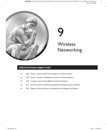
Typical TCP behaviourCongestion Window size(segments)14Congestionavoidance1210Slow startthreshold864Slow start20012345678Time (round trips)Sridhar IyerIIT Bombay84
Slow start phase initialize: Cwnd 1 for (each ACK) Cwnd until loss detection OR Cwnd ssthreshRTTHost AHost Bone segmenttwo segmentsfour segmentstimeSridhar IyerIIT Bombay85
Congestion avoidance phase1Sridhar IyerHost Bfour segmRTT/* Cwnd threshold */ Until (loss detection) {every w ACKs:Cwnd } ssthresh Cwnd/2 Cwnd 1 perform slow startHost Aentsfive segmentstimeIIT Bombay86
TCP: Fast retransmit and Fast recoveryWindow size (segments)10advertised window864After fast recovery200246810 12 14Time (round trips)Sridhar IyerIIT Bombay87
802.11 (WiFi) Overview
Wireless LANs Infrared (IrDA) or radio links (Wavelan) Advantages– very flexible within the reception area– Ad hoc networks possible– (almost) no wiring difficulties Disadvantages– low bandwidth compared to wired networks– many proprietary solutions Infrastructure v/s ad hoc networks (802.11)Sridhar IyerIIT Bombay89
Infrastructure vs. Ad hoc networksinfrastructurenetworkAP: Access PointAPAPwired networkAPad hoc networkSridhar IyerIIT Bombay90Source: Schiller
Difference between wired and wirelessEthernet LANWireless LANBABCAC If both A and C sense the channel to be idle at thesame time, they send at the same time. Collision can be detected at sender in Ethernet. Half duplex radios in wireless cannot detect collisionat sender.Sridhar IyerIIT Bombay91
Carrier Sense Multiple Access (CSMA) Listen before you speak Check whether the medium is active before sending apacket (i.e carrier sensing) If medium idle, then transmit If collision happens, then detect and resolve If medium is found busy, transmission follows:– 1 persistent– P persistent– Non persistentSridhar IyerIIT Bombay92
Collision detection (CSMA/CD) All aforementioned scheme can suffer from collision Device can detect collision– Listen while transmitting– Wait for 2 * propagation delay On collision detection wait for random time beforeretrying Binary Exponential Backoff Algorithm– Reduces the chances of two waiting stations picking thesame random timeSridhar IyerIIT Bombay93
Binary Exponential Backoff1.On detecting 1st collision for packet xstation A chooses a number r between 0 and 1.wait for r * slot time and transmit.Slot time is taken as 2 * propagation delayk. On detecting kth collision for packet xchoose r between 0,1,.,(2k –1) When value of k becomes high (10), give up. Randomization increase with larger window, but delayincreases.Sridhar IyerIIT Bombay94
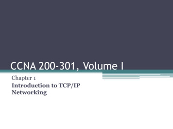
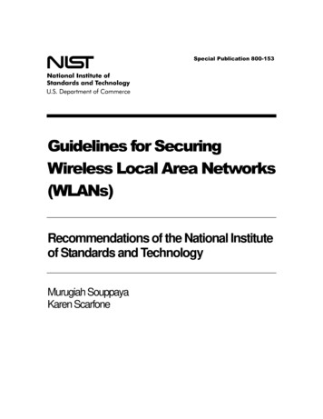
Hidden Terminal ProblemABC– A and C cannot hear each other.– A sends to B, C cannot receive A.– C wants to send to B, C senses a “free” medium(CS fails)– Collision occurs at B.– A cannot receive the collision (CD fails).– A is “hidden” for C.Sridhar IyerIIT Bombay95
Effect of interference rangeTransmission from 1 2 will fail
Solution for Hidden Terminals A first sends a Request to Send (RTS) to B On receiving RTS, B responds Clear to Send (CTS) Hidden node C overhears CTS and keeps quiet– Transfer duration is included in both RTS and CTS Exposed node overhears a RTS but not the CTS– D’s transmission cannot interfere at BRTSDRTSACTSBCTSCDATASridhar IyerIIT Bombay97
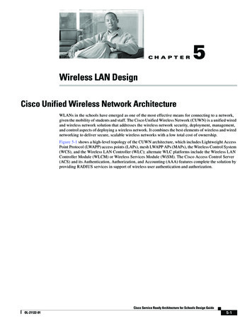
Components of IEEE 802.11architecture The basic service set (BSS) is the basic buildingblock of an IEEE 802.11 LAN The ovals can be thought of as the coverage areawithin which member stations can directlycommunicate The Independent BSS (IBSS) is the simplest LAN. Itmay consist of as few as two stationsad hoc networkSridhar IyerBSS1IIT BombayBSS298
802.11 ad hoc network (DCF)802.11 LANSTA1 Di
Wireless networks Access computing/communication services, on the move Wireless WANs – Cellular Networks: GSM, GPRS, CDMA – Satellite Networks: Iridium Wireless LANs – WiFi Networks: 802.11 – Personal Area Networks: Bluetooth Wireless MANs