Transcription
MicroLogix Ethernet Interface1761-NET-ENI and1761-NET-ENIWUser Manual
Important User InformationSolid state equipment has operational characteristics differing from those ofelectromechanical equipment. Safety Guidelines for the Application,Installation and Maintenance of Solid State Controls (Publication SGI-1.1available from your local Rockwell Automation sales office or online athttp://www.ab.com/manuals/gi) describes some important differencesbetween solid state equipment and hard-wired electromechanical devices.Because of this difference, and also because of the wide variety of uses forsolid state equipment, all persons responsible for applying this equipmentmust satisfy themselves that each intended application of this equipment isacceptable.In no event will Rockwell Automation, Inc. be responsible or liable forindirect or consequential damages resulting from the use or application ofthis equipment.The examples and diagrams in this manual are included solely for illustrativepurposes. Because of the many variables and requirements associated withany particular installation, Rockwell Automation, Inc. cannot assumeresponsibility or liability for actual use based on the examples and diagrams.No patent liability is assumed by Rockwell Automation, Inc. with respect touse of information, circuits, equipment, or software described in this manual.Reproduction of the contents of this manual, in whole or in part, withoutwritten permission of Rockwell Automation, Inc. is prohibited.Throughout this manual we use notes to make you aware of tifies information about practices or circumstancesthat can cause an explosion in a hazardous environment,which may lead to personal injury or death, propertydamage, or economic loss.Identifies information that is critical for successfulapplication and understanding of the product.Identifies information about practices or circumstancesthat can lead to personal injury or death, propertydamage, or economic loss. Attentions help you: identify a hazard avoid a hazard recognize the consequenceSHOCK HAZARDLabels may be located on or inside the drive to alertpeople that dangerous voltage may be present.BURN HAZARDLabels may be located on or inside the drive to alertpeople that surfaces may be dangerous temperatures.
Summary of ChangesThe information below summarizes the changes to this manual sincethe last printing.To help you find new and updated information in this release of themanual, we have included change bars as shown to the right of thisparagraph.Information on 1761-NET-ENI and 1761-NET-ENIW, series D, has beenadded throughout the manual. The table below lists the sections thatdocument new features and additional or updated information onexisting features.1For this information:Seehow to obtain a manual from Rockwell AutomationP-2Series D LED descriptionpage 1-3Ethernet Settingspage 1-6Series D Enhancementspage 1-8Using the RSLinx Ethernet/IP driver with series B ENIs and higherpage 3-5Download location for ENI/ENIW Configuration Utilitypage 4-1Download location for Com Port Redirector softwarepage 4-1Updated examples and information on making configuration settingsusing the ENI/ENIW Configuration Utility, including series Dconfiguration optionspages 4-2 to 4-4Series D Email Authenticationpages 4-5 and6-2Updated information on using the ENI/ENIW Configuration Utility overRS-232page 4-6New information on using the ENI/ENIW Configuration Utility overEthernet (series D only), including using the Com Port Redirectorsoftwarepages 4-8Updated information on configuration node functionspage 4-12Configuring Email Authentication options for series D ENI/ENIWspages 4-20 to4-21Configuring Ethernet speed and duplex settings for series DENI/ENIWspage 4-22Series D Web Page Enhancementschapter 7LED sequence at power-up for series A/B/C/Dpage 9-2Troubleshooting using the LED indicators series A/B/C/Dpage 9-3Series C and D Ethernet specificationspage A-1Updated information on configuration via BOOTPAppendix B1761-NET-ENI/ENIW performance considerationsAppendix CPublication 1761-UM006E-EN-P - August 2005
2Summary of ChangesPublication 1761-UM006E-EN-P - August 2005
Table of ContentsPrefaceWho Should Use this Manual. . . . . . . . . . . . .Purpose of this Manual . . . . . . . . . . . . . . . . .Related Documentation . . . . . . . . . . . . . .Common Techniques Used in this Manual . . .Your Questions or Comments on this 1-71-81-81-81-81-9European Communities (EC) Directive Compliance .EMC Directive . . . . . . . . . . . . . . . . . . . . . . . . . .Low Voltage Directive . . . . . . . . . . . . . . . . . . . .Safety Considerations . . . . . . . . . . . . . . . . . . . . . . .External Power Supply Wiring . . . . . . . . . . . . . . . . .Mounting . . . . . . . . . . . . . . . . . . . . . . . . . . . . . . . .DIN Rail Mounting . . . . . . . . . . . . . . . . . . . . . . .Panel Mounting . . . . . . . . . . . . . . . . . . . . . . . . .ENI/ENIW Port Identification. . . . . . . . . . . . . . . . . .Ethernet Connections . . . . . . . . . . . . . . . . . . . . . . .Ethernet 8-Pin 10/100-Base-T Connector (Port 1).Ethernet Cables . . . . . . . . . . . . . . . . . . . . . . . . .Maintain ENI and ENIW Cable Connections . . . .RS-232 Port Connections . . . . . . . . . . . . . . . . . . . . .RS-232 Connector . . . . . . . . . . . . . . . . . . . . . . .RS-232 Cables . . . . . . . . . . . . . . . . . . . . . . . . . hapter 1Product OverviewEtherNet/IP Connectivity . . .Hardware Features . . . . . . .Product Drawing . . . . . .LED Indicators . . . . . . . .Default Settings . . . . . . .Operating Modes . . . . . . . .Messaging . . . . . . . . . . .Email. . . . . . . . . . . . . . .Device Compatibility . . . . . .Series B Enhancements . . . .Series C Enhancements . . . .Series D Enhancements . . . .Ethernet Networks . . . . . . .Basic Ethernet TopologyWeb Server Functionality. . .Chapter 2Installation and WiringiiiPublication 1761-UM006E-EN-P - August 2005
ivTable of ContentsChapter 3OperationOperation Overview . . . . . . . . . . . . . . . . . . . . . . . . . . . . .Allocation of Ethernet Connections . . . . . . . . . . . . . . . . . .ENI and ENIW Functional Overview . . . . . . . . . . . . . . . . .General Ethernet Information . . . . . . . . . . . . . . . . . . . . . .RSLinx/RSWho Connectivity Example Using ENI/ENIWInterface . . . . . . . . . . . . . . . . . . . . . . . . . . . . . . . . . . . . . .PC Connected Directly to Ethernet (RSLinx on Ethernet)PC Connected to Ethernet via the ENI or ENIW. . . . . . .3-13-13-23-23-23-43-8Chapter 4ENI/ENIW Configuration (Nodes241 to 254)Publication 1761-UM006E-EN-P - August 2005Configuration Methods . . . . . . . . . . . . . . . . . . . . . . .ENI/ENIW Configuration Utility . . . . . . . . . . . . . . . . .Make Configuration Settings . . . . . . . . . . . . . . . . .Save to ENI/ENIW RAM or ENI/ENIW ROM . . . . .Email Settings . . . . . . . . . . . . . . . . . . . . . . . . . . .Message Routing . . . . . . . . . . . . . . . . . . . . . . . . .Reset . . . . . . . . . . . . . . . . . . . . . . . . . . . . . . . . . .Use the Configuration Utility Over RS-232 . . . . . . .Use the Configuration Utility Over Ethernet(Series D only). . . . . . . . . . . . . . . . . . . . . . . . . . .Controller Messaging. . . . . . . . . . . . . . . . . . . . . . . . .ENI/ENIW Configuration Parameters . . . . . . . . . . . . .Node 254 - Ethernet Hardware Address . . . . . . . .Node 253 - Baud Rate . . . . . . . . . . . . . . . . . . . . .Node 252 - BOOTP Configuration . . . . . . . . . . . .Node 251 - Email Server. . . . . . . . . . . . . . . . . . . .Node 250 - TCP/IP Configuration . . . . . . . . . . . . .Node 249 - From String . . . . . . . . . . . . . . . . . . . .Node 248 - Save/Reset Function . . . . . . . . . . . . . .Node 245 - Configuration Security Mask . . . . . . . .Node 244 - SMTP Email Authentication Checkbox(Series D Only) . . . . . . . . . . . . . . . . . . . . . . . . . .Node 243 - SMTP Email Authentication Password(Series D Only) . . . . . . . . . . . . . . . . . . . . . . . . . .Node 242 - SMTP Email Authentication Username(Series D Only) . . . . . . . . . . . . . . . . . . . . . . . . . .Node 241 - Ethernet Speed and Duplex Setting(Series D Only) . . . . . . . . . . . . . . . . . . . . . . . . . .Configuring ENI/ENIW Data Parameters. . . . . . . . . . .Configuring ENI/ENIW String Parameters . . . . . . . . . .Configuring the ENI/ENIW Email From String . . . -154-154-194-194-20. . . . 4-20. . . . 4-21. . . . 4-21.4-224-224-244-24
Table of ContentsvChapter 5Peer-to-Peer MessagingMessaging Between the ENI/ENIW and DF1 Devices . . . . . 5-1Message to Configuration Nodes (Nodes 100 to 149) and Sendinga Message to a Destination Controller (Nodes 0 to 49) . . . . 5-2Chapter 6EMail Messages (Node 50 to 99)Overview . . . . . . . . . . . . . . . . . . . . .Configuring Email . . . . . . . . . . . . . . .SMTP Email Address . . . . . . . . . .Destination Addresses . . . . . . . . .Message Text. . . . . . . . . . . . . . . .Message Fields (to, from, subject) .Sending an Email Message. . . . . . . . .6-16-26-26-36-36-46-4Web Browser Compatibility . . . . . . . . . . . . . . . . . . . . . . .Series D ENIW Web Pages. . . . . . . . . . . . . . . . . . . . . . . .Home Page. . . . . . . . . . . . . . . . . . . . . . . . . . . . . . . . . . .Defining URL Links . . . . . . . . . . . . . . . . . . . . . . . . . . . . .Displaying Device Data . . . . . . . . . . . . . . . . . . . . . . . . . .String Data . . . . . . . . . . . . . . . . . . . . . . . . . . . . . . . .Integer Data . . . . . . . . . . . . . . . . . . . . . . . . . . . . . . .Floating-point Data . . . . . . . . . . . . . . . . . . . . . . . . . .Writing Data to the ENIW. . . . . . . . . . . . . . . . . . . . . .Auto-Refresh of Data View Pages . . . . . . . . . . . . . . . .ENIW Update Timer . . . . . . . . . . . . . . . . . . . . . . . . . . . .Posting Data to the Device . . . . . . . . . . . . . . . . . . . . . . .Setting Passwords for Data View Pages . . . . . . . . . . . .Posting Data . . . . . . . . . . . . . . . . . . . . . . . . . . . . . . .Display Event Data . . . . . . . . . . . . . . . . . . . . . . . . . . . . .Display Diagnostic Data . . . . . . . . . . . . . . . . . . . . . . . . .Display Configuration . . . . . . . . . . . . . . . . . . . . . . . . . . .Use the ENIW Utility to Configure the ENIW’s Web ServerFunctionality . . . . . . . . . . . . . . . . . . . . . . . . . . . . . . . . . .Configure the Home Page . . . . . . . . . . . . . . . . . . . . .Configure Data View Pages . . . . . . . . . . . . . . . . . . . 7-127-13Chapter 71761-NET-ENIW Web ServerCapabilities. 7-14. 7-14. 7-14Chapter 8Connecting CompactLogixControllers on EthernetSystem Diagram . . . . . . . . . . . . . . . . . . . . . . . . . . . . . . . .Purpose . . . . . . . . . . . . . . . . . . . . . . . . . . . . . . . . . . . . . .Scope . . . . . . . . . . . . . . . . . . . . . . . . . . . . . . . . . . . . . . . .General CompactLogix Messaging Guidelines. . . . . . . . . . .Configure ENI #1 . . . . . . . . . . . . . . . . . . . . . . . . . . . . . . .Configure ENI #2 . . . . . . . . . . . . . . . . . . . . . . . . . . . . . . .Configure ENI #2 Via the ENI/ENIW Configuration Utility8-28-38-38-48-58-78-8Publication 1761-UM006E-EN-P - August 2005
viTable of ContentsConfiguration Via Ladder Logic. . . . . . . . . . . . . . . . . . . 8-10Download To The CompactLogix Controller Through Two SeriesA ENIs . . . . . . . . . . . . . . . . . . . . . . . . . . . . . . . . . . . . . . . 8-17Download to the CompactLogix Controller Through a ENI/ENIWSeries B/C/D via Ethernet . . . . . . . . . . . . . . . . . . . . . . . . . 8-19Create MSG Programs for the SLC 5/05 and the ControlLogixControllers . . . . . . . . . . . . . . . . . . . . . . . . . . . . . . . . . . . . 8-21Chapter 9TroubleshootingNetwork Troubleshooting . . . . . . . . . . . . .Maintain ENI/ENIW Cable Connections.Using ENI/ENIW with Routers . . . . . . . . . .LED Sequence at Power-Up. . . . . . . . . . . .Troubleshooting Using the LED Indicators .Error Codes Generated by the ENI/ENIW. .9-19-19-19-29-39-6.A-1A-1A-1A-2Appendix ASpecificationsPhysical Specifications. . . . . . . . . . . . .Series C and D Ethernet Specifications .MicroLogix Web Site . . . . . . . . . . . . . .Dimensions. . . . . . . . . . . . . . . . . . . . .Appendix BBOOTP Configuration Method(default)ENI/ENIW BOOTP Operation . . . . . . . . . . . . . . . . . . . . . . B-2Using the Rockwell BOOTP/DHCP Utility . . . . . . . . . . . . . B-3Appendix C1761-NET-ENI/ENIW Performance Ethernet/IP Connections . . . . . . . . . . . . . . . . . . . . . . . . . . C-1Packet Size Limitations . . . . . . . . . . . . . . . . . . . . . . . . . C-1ConsiderationsData Throughput . . . . . . . . . . . . . . . . . . . . . . . . . . . . . C-2GlossaryIndexPublication 1761-UM006E-EN-P - August 2005
PrefaceRead this preface to familiarize yourself with the rest of the manual. Itprovides information concerning: Who Should Use thisManualwho should use this manualthe purpose of this manualrelated documentationconventions used in this manualRockwell Automation supportUse this manual if you are responsible for designing, installing,programming, or troubleshooting control systems that useAllen-Bradley Controllers on Ethernet.You should have a basic understanding of Allen-Bradleyprogrammable controllers and Ethernet networking. You shouldunderstand programmable controllers and be able to interpret theladder logic instructions required to control your application. If youdo not, contact your local Allen-Bradley representative for informationon available training courses before using this product.Purpose of this Manual1This manual is a reference guide for the Ethernet Interface (ENI) andWeb-enabled Ethernet Interface (ENIW). It describes the proceduresyou use to install and configure the ENI and ENIW.Publication 1761-UM006E-EN-P - August 2005
Preface2Related DocumentationThe following documents contain additional information concerningRockwell Automation products. To obtain a copy, contact your localRockwell Automation office or distributor.ForRead this DocumentDocument NumberInstructions on installing a 1761-NET-ENI or 1761-NET-ENIW InterfaceConverter.Ethernet Interface InstallationInstructions1761-IN007Information on DF1 open protocol.DF1 Protocol and Command SetReference Manual1770-6.5.16In-depth information on designing, implementing, and maintaining anEtherNet/IP Media Planning andindustrial control system using EtherNet/IP (Ethernet Industrial Protocol) Installation ManualENET-IN001In-depth information on grounding and wiring Allen-Bradleyprogrammable controllersAllen-Bradley ProgrammableController Grounding and WiringGuidelines1770-4.1A description of important differences between solid-stateprogrammable controller products and hard-wired electromechanicaldevicesApplication Considerations forSolid-State ControlsSGI-1.1An article on wire sizes and types for grounding electrical equipmentNational Electrical Code - Published by the National FireProtection Association of Boston, MA.A glossary of industrial automation terms and abbreviationsAllen-Bradley Industrial AutomationGlossaryAG-7.1If you would like a manual, you can: download a free electronic version from the internet atwww.rockwellautomation.com/literature. purchase a printed manual by contacting your localAllen-Bradley distributor or Rockwell Automation sales office.Common Techniques Usedin this ManualPublication 1761-UM006E-EN-P - August 2005The following conventions are used throughout this manual: Bulleted lists such as this one provide information, notprocedural steps. Numbered lists provide sequential steps or hierarchicalinformation. Italic type is used for emphasis. ENI/ENIW is used when information and instructions areapplicable to both the 1761-NET-ENI and 1761-NET-ENIW. Incases where information applies to only one type of interface,the appropriate model and series is identified.
PrefaceYour Questions orComments on this Manual3If you find a problem with this manual, or you have any suggestionsfor how this manual could be made more useful to you, pleasecontact us at the address below:Rockwell AutomationAutomation Control and Information GroupTechnical Communication, Dept. A602VP.O. Box 2086Milwaukee, WI 53201-2086or visit our internet page at:http://www.rockwellautomation.comPublication 1761-UM006E-EN-P - August 2005
Preface4Publication 1761-UM006E-EN-P - August 2005
Chapter1Product OverviewThis chapter gives an overview of the Ethernet Network Interface. Thefollowing topics are covered: EtherNet/IP ConnectivityEtherNet/IP ConnectivityHardware FeaturesOperating ModesDevice CompatibilityEnhancements by SeriesEthernet NetworksWeb-Server FunctionalityThe 1761-NET-ENI and 1761-NET-ENIW provide EtherNet/IPconnectivity for all MicroLogix controllers, CompactLogix controllers,and other DF1 full-duplex devices. The Ethernet Network Interface,ENI or ENIW, allows you to easily connect non-Ethernet controllersonto new or existing Ethernet networks and upload/downloadprograms, communicate between controllers, and generate emailmessages via SMTP (simple mail transport protocol).EtherNet/IP is an industry standard open protocol which providesinter-device compatibility. You can exchange information with otherAllen-Bradley Ethernet controllers (SLC, PLC, and ControlLogix) in apeer-to-peer relationship, so you do not need any master-type device.The ENI and ENIW also support an SMTP mail service that allows anexisting controller to send email messages to any destinationconnected to the network. The email can be used to initiate thetransmission of data or status information.1Publication 1761-UM006E-EN-P - August 2005
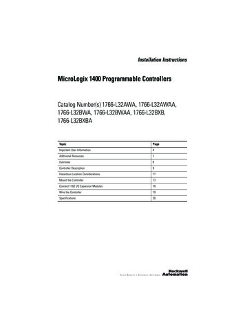
1-2Product OverviewHardware FeaturesProduct DrawingRS-232Mini-DIN PortETHERNETINTERFACEEthernet PortSeries A/B: 10-Base-TSeries C/D: 10/100-Base-TCATSER FRN1761-NET-ENIB 2.20E N I *B 2 2 0 0 1 0 2 0 0 0 1FAC .xxEthernet HardwareAddressLISTED IND.CONT.EQ. FOR HAZ.CRA196US LOC.OPERATING TEMPERATURE CODE T3CCLASS I, GROUPS A,B,C, AND D, DIV 2N223ETHERNET ADDRESSF F -F F -F F -F F -F F -F FEXTERNAL POWER REQUIREMENTS24 V dc 10/-15% AT 100 mAN.E.C. CLASS 2IP AddressWrite-On AreaUSE EXTERNAL DC SOURCEFOR CLASS I DIVISION 2APPLICATIONS. SEEINSTALLATION INSTRUCTIONSMADE IN U.S.A.CHSGNDDCNEUT24VDCLED IndicatorsThe ENI and ENIW have five LED indicators:Table 1.1 Series A/B DescriptionsSeries A/BFAULTLINKEthernet TX/RXLEDDescriptionFunctionColorRS-232TX/RXRS-232 datatransmission indicatorflashes when the RS-232 port istransmitting or receiving datagreenPOWERmodule powerlit when module is poweredgreenLINKEthernet link statuslit when there is a valid physicalEthernet connectiongreenEthernetTX/RXEthernet datatransmission indicatorflashes when the Ethernet port istransmitting or receiving datagreenindicates Ethernet network traffic toand from the ENI/ENIWRS-232 TX/RXFAULTPOWERPublication 1761-UM006E-EN-P - August 2005fault condition indicator lit when a fault condition is presentred orflashingred
Product Overview1-3Series CFAULT10100RS-232 TX/RXPOWERTable 1.2 Series C RS-232 datatransmission indicatorRS-232 port is transmitting or receiving flashingdatagreenno RS-232 trafficoffPOWERmodule powermodule is poweredgreen1010-Base-T Ethernetlink status and datatransmission indicatorNo link or continuous data activityoff10-Base-T Half Duplex; Link goodhowever no data activityamber10-Base-T Half Duplex; Link good withsporadic data activity(1)flashingamber10-Base- T Full Duplex; Link goodhowever no data activitygreen10-Base-T Full Duplex; Link good withsporadic data activity(1)flashinggreenNo link or continuous data activityoff100-Base-T Half duplex; Link goodhowever no data activityamber100-Base-T Half Duplex; Link goodwith sporadic data activity(1)flashingamber100-Base-T Full Duplex; Link goodhowever no data activitygreen100100-Base-T Ethernetlink status and datatransmission indicator100-Base-T Full Duplex; Link good with flashinggreensporadic data activity(1)FAULTfault conditionindicatorlit when a fault condition is presentred orflashing red(1) Any Ethernet network activity; not necessarily to or from the ENI/ENIW.Publication 1761-UM006E-EN-P - August 2005
1-4Product OverviewSeries DFAULTLINKEthernet TX/RXRS-232 TX/RXPOWERTable 1.3 Series D RS-232 datatransmission indicatorRS-232 port is transmitting orreceiving dataflashing greenno RS-232 trafficoffmodule is poweredgreenPOWERmodule powerLINKEthernet link status and No link10-Base-T or10-Base-T link100-Base-T indicator100-Base-T linkEthernetTX/RXFAULTEthernet activity statusand Half Duplex or FullDuplex statusfault conditionindicatoroffambergreenNo activityoffHalf Duplex activity(1)flashing amberFull Duplex activity(1)flashing greenlit when a fault condition ispresentred or flashingred(1) Any Ethernet network activity; not necessarily to or from the ENI/ENIW.After out-of-box power-up, the most common reason for a flashingred fault LED is because an IP address has not yet been assigned viaBOOTP. Either set up a BOOTP server to assign an IP address ormodify the ENI/ENIW configuration to use a specific IP address or toobtain an IP address via a DHCP server.For more detailed information on LED operation, see Chapter 9,Troubleshooting.Publication 1761-UM006E-EN-P - August 2005
Product OverviewIMPORTANT1-5The IP addresses in any of the examples in thismanual were arbitrarily assigned and should only beused on an isolated Ethernet network. Contact yoursystem administrator for unique IP addresses if youare connecting your Ethernet devices to youremployer’s Ethernet network.Default SettingsThe ENI/ENIW has the following default settings:Table 1.4 RS-232 SettingsSettingDefaultOther OptionsBaud RateAutobaudsee table 4.2Handshaking (hardware, software)nonenoneData Bits8noneStop Bits1noneParitynonenoneSettingDefaultOther OptionsDuplicate Message DetectionEnablednoneError DetectionAuto-detect (forAutobaud)Auto-detect whenAutobaud is true,otherwise CRCEmbedded Response OperationDisabled(1)noneDLE ACK Timeout1 secondnoneDLE NAK Receive3 NAK retriesnoneDLE ENQ for Response3 ENQs retriesnoneDF1 Node AddressDon’t CareTable 1.5 DF1 Settings(1) Connected controllers should be configured for Embedded Responses Disabled or Auto-detect.Publication 1761-UM006E-EN-P - August 2005
1-6Product OverviewTable 1.6 Ethernet SettingsSettingDefaultOther OptionsEthernet Speed/Duplex10 Mbps half-duplex(series A, B)Auto Negotiate (series C, D)0 Auto Negotiate1 10 Mbps half-duplex2 10 Mbps full-duplex3 100 Mbps half-duplex4 100 Mbps full-duplexSMTP Username(1)null45 character usernameSMTP Password(1)null45 character passwordSMTP Authentication(1)Disabled0 Disabled1 EnabledConfiguration SecurityMask000.000.000.000Valid IP addressSave/Reset(2)n/a0 save configuration to flash1 simple reset2 reset to out-of-box defaults3 reset to out-of-box, exceptmaintain current IPconfigurationFrom StringENI192.168.1.254@eni1761. ENI/ENIW Identifierorg(4)IP Address000.000.000.000192.168.1.254(1)valid IP AddressSubnet Mask0.0.0.0(5)valid subnet mask(1)Gateway Address0.0.0.0valid IP addressSecurity Mask 10.0.0.0valid IP addressSecurity Mask 20.0.0.0valid IP addressEmail Server000.000.000.000valid IP addressBOOTP Configuration00 BOOTP initially1 BOOTP/DHCP disabled2 BOOTP fallback(6)3 BOOTP always(6)4 DHCP always(6)Baud Rate(3)See page 4-14.Autobaud enabled withautodetect of CRC/BCCEthernet HardwareAddressFactory Value - Read Only(see the nameplate on theunit)Factory Value(1) Series D only.(2) See page 4-19.(3) Changes to the Baud Rate take effect when the ENI/ENIW power is cycled, or the configuration is saved toflash.(4) TThe ENI/ENIW address, 192.168.1.254 will be replaced by the IP address assigned to the ENI/ENIW. Forexample, the string may be ENI191.225.181.52@eni1761.org. If the ENI/ENIW does not have an assigned IPaddress, the string will be read as ENI192.168.1.254@eni1761.org for the series D or ENI0.0.0.0@eni1761.orgfor series A, B, or C.(5) See page 4-17 for Subnet Mask auto-detect mode details.(6) Series C and higher.Publication 1761-UM006E-EN-P - August 2005
Product OverviewOperating Modes1-7MessagingWhen the ENI/ENIW is connected to a programmable controller (andconnected to an Ethernet network), the controller can be accessedfrom other devices on Ethernet, or initiate communications to otherEtherNet/IP devices.EmailThe ENI/ENIW also support SMTP mail service, which allows acontroller to send email messages to any email address on thenetwork. The email can be used to initiate the transmission of data orstatus information.Device CompatibilityThe ENI/ENIW are compatible with the following devices andapplications: All MicroLogix, SLC, PLC-5, CompactLogix, FlexLogix, andControlLogix controllers, which support DF1 Full-Duplex on anavailable RS-232 port Personal Computers using the RSLinx (V2.30.00 and higher) DF1Full-Duplex Driver Other DF1 Full-Duplex compliant products that have at least oneRS-232 port, for example, operator interface devices RSLinx (V2.31.00 and higher) Ethernet DriverSeries B EnhancementsThe 1761-NET-ENI series B features the following enhancements: elimination of the need for two ENIs in a CompactLogix,FlexLogix, or ControlLogix system using RSLogix 5000 ability to use Dynamic Host Configuration Protocol (DHCP) two new BOOTP optionsThe 1761-NET-ENIW has the same features as the 1761-NET-ENI, butincludes web-serving capabilities as discussed on page 1-9.Publication 1761-UM006E-EN-P - August 2005
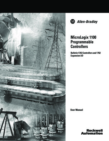
1-8Product OverviewSeries C EnhancementsThe 1761-NET-ENI/ENIW series C features the followingenhancements: 10/100-Base-T Ethernet port that auto-negotiates between10 Megabits per second and 100 Megabits per second, eitherhalf-duplex or full-duplex. increased temperature range up to 60 C (140 F) increased messaging performanceSeries D EnhancementsThe ENI/ENIW series D features the following enhancements: Ability to configure the ENI/ENIW over Ethernet Email user authentication for open mail servers Ability to force 10 Mbps or 100 Mbps and half-duplex orfull-duplex Ethernet configuration Diagnostic web-page for Ethernet connections in use Revised web-page formats for ENIWEthernet NetworksBasic Ethernet TopologyThe ENI/ENIW Ethernet connectors conform to ISO/IEC 8802-3 STD802.3 and utilizes 10/100 Base-T media. Connections are made directlyfrom the ENI/ENIW to an Ethernet switch. The network setup issimple and cost effective. Typical network topology is pictured below.EthernetSwitchto PC Ethernet Card orother Ethernet DevicePublication 1761-UM006E-EN-P - August 2005RJ45 connectors onboth ends of cable(10/100 Base-T)to ENI or ENIW
Product OverviewIMPORTANTWeb Server Functionality1-9The ENI/ENIW provides a 10/100 Base-T, RJ45Ethernet connector which connects to standardEthernet hubs and switches via an 8-wire twistedpair straight-through cable. To access other Ethernetmediums, use 10/100 Base-T media converters orEthernet switches that can be connected together viafiber, thin-wire, or thick-wire coaxial cables, or anyother physical media commercially available withEthernet switches. See page 2-6 for more cableinformation.The ENIW enhances operation with web server functionality, enablingit to: display 40 data table values on 4 standard Data View web pagesconsisting of 7 integer and 3 floating-point values on each page, display 10 user-configurable data description strings on eachData View web page, display a diagnostic page with status and IP Address of activeEthernet connections (series D only), password protect writable data files to prevent unauthorizedmodification, and provide 10 user-configurable web page links.You can access information about the ENI/ENIW via your webbrowser. Simply enter it’s TCP/IP address into the address field ofyour browser.See Chapter 7 for details on using the ENIW’s web server capabilities.Publication 1761-UM006E-EN-P - August 2005
1-10Product OverviewPublication 1761-UM006E-EN-P - August 2005
Chapter2Installation and WiringThis chapter covers installation and wiring for the ENI/ENIW. It isdivided into the following sections: European Communities (EC)Directive ComplianceEuropean Communities (EC) Directive ComplianceSafety ConsiderationsMountingExternal Power Supply WiringENI/ENIW Port IdentificationEthernet ConnectionsRS-232 Port ConnectionsThis product has the CE mark. It is approved for installation within theEuropean Union and EEA regions. It has been designed and tested tomeet the following directives.EMC DirectiveThis product is tested to meet the Council Directive 89/336/ECElectromagnetic Compatibility (EMC) by applying the followingstandards, in whole or in part, documente
Information on 1761-NET-ENI and 1761-NET-ENIW, series D, has been added throughout the manual. The table below lists the sections that document new features and additional or updated information on existing features. For this information: See how to obtain a manual from Rockwell Automation P-2 Series D LED description page 1-3 Ethernet Settings .