Transcription
Operating Manualfor flow meters of the product line:“VSI High Definition Flow Meter“Grey cast iron versionStainless steel versionVSE Volumentechnik GmbHHönnestraße 4958809 Neuenrade / GermanyPhone 49 (0)23 94 /616 30Fax 49 (0)23 94 /616 33E-Mail info@vse-flow.comInternet www.vse-flow.com1
Table of ContentsPageImportant basic information. . . . . . . . . . . . . . . . . . . . . . . . . . . . . . . . . . . . . . . . . . . . . . . . . . . . . 3General function description of flow meter. . . . . . . . . . . . . . . . . . . . . . . . . . . . . . . . . . . . . . . . . 4General description. . . . . . . . . . . . . . . . . . . . . . . . . . . . . . . . . . . . . . . . . . . . . . . . . . . . . . . . . . . 4Flow meter selection. . . . . . . . . . . . . . . . . . . . . . . . . . . . . . . . . . . . . . . . . . . . . . . . . . . . . . . . . . . 4Declaration of Conformity. . . . . . . . . . . . . . . . . . . . . . . . . . . . . . . . . . . . . . . . . . . . . . . . . . . . . . 4General conditions for initial start-up . . . . . . . . . . . . . . . . . . . . . . . . . . . . . . . . . . . . . . . . . . . . . 4Maximum operating pressure. . . . . . . . . . . . . . . . . . . . . . . . . . . . . . . . . . . . . . . . . . . . . . . . . . . 5Statement to EU-Directive 97/23/EG, Pressurized devices. . . . . . . . . . . . . . . . . . . . . . . . . . . . 5Flow meter range. . . . . . . . . . . . . . . . . . . . . . . . . . . . . . . . . . . . . . . . . . . . . . . . . . . . . . . . . . . . . 6Assembly of the flow meter . . . . . . . . . . . . . . . . . . . . . . . . . . . . . . . . . . . . . . . . . . . . . . . . . . . . . 6Cleaning and flushing of pipe lines before initial start-up . . . . . . . . . . . . . . . . . . . . . . . . . . . . . 7Filtering of liquid. . . . . . . . . . . . . . . . . . . . . . . . . . . . . . . . . . . . . . . . . . . . . . . . . . . . . . . . . . . . . . 7Flow meters with high definition of volume measurement. . . . . . . . . . . . . . . . . . . . . . . . . . . . . . 8Technical specifications of preamplifier . . . . . . . . . . . . . . . . . . . . . . . . . . . . . . . . . . . . . . . . . . 13Plug assignment of preamplifier . . . . . . . . . . . . . . . . . . . . . . . . . . . . . . . . . . . . . . . . . . . . . . . . 14Maintenance. . . . . . . . . . . . . . . . . . . . . . . . . . . . . . . . . . . . . . . . . . . . . . . . . . . . . . . . . . . . . . . . 14Sending back of repairs and sample devices. . . . . . . . . . . . . . . . . . . . . . . . . . . . . . . . . . . . . . . 15Technical specifications VSI 0.02 / IPF – VSI 4 / IPF . . . . . . . . . . . . . . . . . . . . . . . . . . . . . . . . 15Flow response curves VSI 0.02 – VSI 4. . . . . . . . . . . . . . . . . . . . . . . . . . . . . . . . . . . . . . . . . . . 16Dimensions VSI 0.02 – VSI 4. . . . . . . . . . . . . . . . . . . . . . . . . . . . . . . . . . . . . . . . . . . . . . . . . . . . 17Dimensions, subplates AP. 02 - 4. . . . . . . . . . . . . . . . . . . . . . . . . . . . . . . . . . . . . . . . . . . . . . . . 18Technical specifications VSI 10 / IPF . . . . . . . . . . . . . . . . . . . . . . . . . . . . . . . . . . . . . . . . . . . . . 19Flow response curves VSI 10 . . . . . . . . . . . . . . . . . . . . . . . . . . . . . . . . . . . . . . . . . . . . . . . . . . . 19Dimensions VSI 10. . . . . . . . . . . . . . . . . . . . . . . . . . . . . . . . . . . . . . . . . . . . . . . . . . . . . . . . . . . 20Dimensions, subplate APG 10. . . . . . . . . . . . . . . . . . . . . . . . . . . . . . . . . . . . . . . . . . . . . . . . . . 20Type key. . . . . . . . . . . . . . . . . . . . . . . . . . . . . . . . . . . . . . . . . . . . . . . . . . . . . . . . . . . . . . . . . . . . 21Plug assignment . . . . . . . . . . . . . . . . . . . . . . . . . . . . . . . . . . . . . . . . . . . . . . . . . . . . . . . . . . . . . 22Preamplifier-block wiring diagram . . . . . . . . . . . . . . . . . . . . . . . . . . . . . . . . . . . . . . . . . . . . . . 22Connection diagram . . . . . . . . . . . . . . . . . . . . . . . . . . . . . . . . . . . . . . . . . . . . . . . . . . . . . . . . . . 232
Important basic informationDear customer, dear user,These installation and operating instructions should provide you with the information you need to properly install and commissionthe flow meter. The installation, commissioning and testing are to be performed by trained and qualified personnel only. These operating instructions must be read and applied carefully to ensure proper, trouble-free and safe operation of the flow meter. VSE is notliable for any damage incurred resulting from not complying with the instructions in this operating instruction. It is not permitted inany case to open the device.These operating instructions for the flow meters of the series ”VSI High Definition Flow Meter” from VSE must be stored, so thatthey can be read by the group of authorized personnel at any time. Chapters may not be taken of these instructions at any time. Amissing operating instructions manual or missing pages must be replaced immediately. VSE can supply you with new instructions oryou can download the operating instructions from the internet (www.vse-flow.com). The operating instructions must be given to eachsubsequent user of this product.Legal informationThis document is not managed by an updating service of VSE Volumentechnik GmbH.Changes to this document may be made without notice.VSE Volumentechnik GmbH does not provide any implicit guarantees of commercial qualities and suitability for a specific purpose.If the device has been opened, modified or incorrectly connected to the electrical circuits, the guarantee of VSE VolumentechnikGmbH for safe operation is void. VSE Volumentechnik GmbH is not liable in any way for personal injuries or damage to goodsresulting from improper installation or improper operating of the flow meter.Operating manual–no.: E060024 (E)Date 31st May 20063
General function description of flow meterFlow meters made by VSE Volumentechnik GmbH measure the volumeflow of liquids according to the toothed wheel principle. A pair of very precisely adjusted toothed wheels in the housing constitutes the meter. A signalpick-up system registers meter rotation free of contact and tooth by tooth.In flow meters of high resolution (VSI), each tooth is output as a multiple ofdigital pulses, depending on interpolation setting.The gaps within the teeth of the meter wheels, form meter chambers in theareas, in which they are completely enclosed by the housing walls; thesechambers digitalise liquid flow depending on their chamber volume.The liquid flow within one meter rotation of a tooth division is divided by theset interpolation factor. This gives the volume measurement per pulse (Vm)and is defined in cm3/pulse. It identifies the constructional size of a flowmeter (e.g. VSI 1/16). General descriptionPlease follow all instructions in this operating manual; only this guaranteestrouble-free operation of the flow meters. VSE is not liable for any damageensuing from not following of these instructions.Opening the devices during the term of guarantee is only authorised afterconsultation and approval of VSE. Flow meter selectionThe correct selection (version) of type and constructional size iscrucial for a trouble-free and safe operation of the flow meters.Owing to the great number of various applications and flow meterversions, the technical specifications in the VSE catalogue materialare of a general nature. Performance of the flow meter depends ontype, size and meter range and on the liquid that is to be measured.Please consult VSE for an exact description. Declaration of ConformityFlow meters of the “VSI” product line are tested for their electromagneticcompatibility and interference transmission in terms of the law on electromagnetic compatibility and correspond to the legal prescriptions enforcedby EMC directives. They may not be operated independently and are to beconnected via cable to a power source and supply digital electric signalsfor electronic evaluation. A declaration of conformity is submitted for allflow meters, which you can request if you require.Since the electromagnetic compatibility of the total measuring system depends on cable layout, correct connection of protective shiel-ding and each single connected device. You must ensure that allcomponents correspond to the electromagnetic compatibility directives and that the electromagnetic compatibility of the total system,machine or plant is guaranteed.All flow meters are tested according to the valid, legally prescribed electromagnetic compatibility directives EN 55011 and EN 61000 and possessthe CE-certification. The EC-declaration of conformity is the CE-label attached to all flow meters. General conditions for initial start-upBefore assembly and before initial start-up, you have to note the followingproperties and aspects of the corresponding characteristics of your system,so that a trouble-free and safe operation is possible.1. The process fluid Is the flow meter suitable for the medium? Is the fluid viscous or abrasive? Is the fluid contaminated or is there solid matter in the fluid? Which granular size does the solid matter possess and can it block the meter? Does the fluid have fillers or other additional material? Is it necessary to install a pre-switched hydraulic filter? Are the pipe lines clean and free of assembly residues such as swarf, weld chips? Is the tank clean and is it ensured that no extraneous materials can get into the pipe line system from the tank? Is the fluid often changed and is sufficient flushing performed in this case? Are the pipe lines and the entire system completely deaerated? What cleaning agent is being used? Are the fluid and the cleaning agent compatible with the seals? Are the seals suitable for the fluid undergoing measurement (seal compatibility)?4
2. The hydraulic properties of the system Is the max. operating pressure of the system lower than the max. permitted operating pressure of the flow meter? Is the max. fall of pressure p (on flow meter) below the max. permitted fall of pressure? Does an excessively great fall in pressure p occur on the flow meter at max. flow (e.g. with higher viscosity)? Does the flow range of the flow meter (depending on viscosity) correspond to the provided flow? Note that flow range decreases the greater the viscosity! Does the temperature range of the flow meter correspond to the provided max. temperature of the medium? Is the cross section of the pipe line large enough and are the falls in pressure in the system not excessive? Is the hydraulic connection (supply and reverse flow) correctly connected and leak-proof? Has the pump sufficient power to operate the system? A blocking flow meter can stop the whole flow. Is a pressure control valve / bypass provided in the system?3. Electronic evaluation and electrical safety Have you selected the optimal flow meter and is this equipped with the appropriate preamplifier? Does the power supply voltage of the flow meter correspond to the provided voltage? Is the power supply voltage supplied by the mains or evaluation device sufficiently steady? Does the output of the power supply voltage correspond to the required power output? Has the electric connection been installed based on the enclosed connection plan? Is the cable protective shielding correctly connected on both sides on the earth conductor PE? Is there a potential difference between the earth conductor PE on the flow meter and the earth conductor PE on the evaluation device? Does a correcting lead have to be laid to eliminate the potential difference between the flow meter and the evaluation device? Is the flow meter connected firmly to the earth conductor PE (e.g. via the pipe lines)? Is the meter constructed to be insulated to the earth conductor PE (e.g. connection via hoses)? If this is the case, the meter has to be connectedwith the earth conductor PE! Is there a continuous connection of the cable protective shielding (earth conductor PE) via the housing, of the 4 or 5-pin round plug to thehousing of the flow meter? Is the cable laid fault-free and the installation secured from input of interference pulses? Is the 4 or 5-pin round plug of the connection cable firmly screwed together with the plug of the flow meter? Are the wires on the evaluation device correctly and properly connected? Does the entire system correspond to the directives of the electromagnetic compatibility laws (EMC)? Have all local valid regulations, applicable directives, guidelines and background conditions of the electromagnetic compatibility lawsbeen maintained and observed? Systems that can lead to personal injury through malfunction or failure are to be equipped with the appropriate safety devices. The functioningof these safety devices is to be checked at regular intervals. Maximum operating pressureBefore assembling the flow meter, you have to test that the max. operating pressure of the system does not exceed the max. permitted operatingpressure of the flow meter. Meanwhile, observe the top pressures that canoccur, when operating the system.The following operating pressures are permitted depending on flow meterversion: Flow meter in grey cast iron versionFlow meter in stainless steel versionpmax 315 bar /4500 psipmax 450 bar /6500 psiImportant:Please consult VSE for all operating pressures 450 bar / 6500 psi and for special versions. Statement to EU-Directive 97/23/EG, Pressurized devicesVSE flow meter are pressurized devices according to article 1, paragraph2.1.4. of above mentioned directive. Therefore they are subject to the regulations to this directive.According to article 3, paragraph 1.4, VSE flow meters have to conformwith the technical requirements of the guideline. The fluids to be measuredare belonging in most of all cases to the class 2, defined in article 9, paragraph 2.2. VSE flow meter do not reach the limit values as defined in article3, paragraph 1.1.The technical requirements for VSE flow meters therefore are limited to theparts indicated in article 3, paragraph 3. It means the devices have tobe designed and manufactured in conformity with acknowledged engineering, such as practiced in one of the member states. This is herewithconfirmed.Beside this the paragraph declares that these devices must not have a CEmarking according to Directive 97/23/EG. Therefore we do not issue declarations of CE and our products are not labelled acc. to 97/23/EG.5
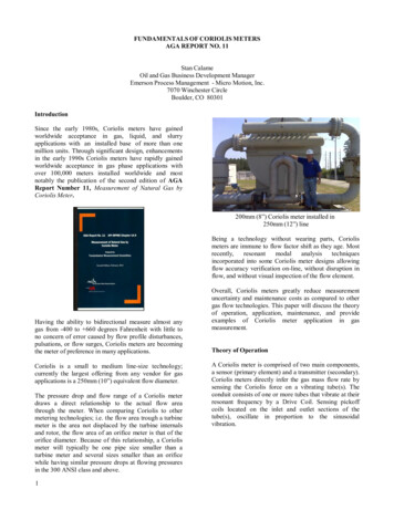
Flow meter rangeThe flow meter range specified in the flow meter data sheet (Qmin - Qmax)refers to the testing fluid “hydraulic oil“ with a viscosity of 21 mm2/s at atemperature of 20 C. For this flow meter range, VSE specifies measurementaccuracy of up to 0.3% of the measurement value and a repetition accuracy of 0.05%.For fluids of lower viscosity ( 21 mm2/s) measurement accuracy deteriorates, while for fluids of higher viscosity ( 21 mm2/s) it can improve.Also note, however, that the flow meter range is restricted in case of higherviscosity (see flow meter data sheet).Important:Make sure that the specified maximum permitted operating pressure of the flow metercannot be exceeded, whatever the operating mode of the system. Note the flow meterrange that is dependent on the viscosity of the fluid to be measured. Assembly of the flow meterThe flow meter should be mounted on an easily accessible location, so thatdismantling for cleaning the meter presents no problem. Since flow meterscan work in any installation position and flow direction, you can mount it onany location of your system. Take care, when installing the flow meter thatliquid always remains in the flow meter, even at system standstill and that itcan never run empty. The outflow of the flow meter should therefore alwaysshow a certain back pressure, since this clamps the flow meter firmly in theliquid column (the meter supports itself through this on the liquid column)and the pipe line cannot run empty. In critical cases or when the pipe lineis at standstill or standby and can run empty, we recommend installing anextra non-return valve in the outflow line.Non-return valveFlow meterTankFig. 1: Flow meter installation with non-return valveImportant:Make sure that the flow meter is always completely filled both in inflow and outflowand that the outflow has a little back pressure. This prevents the meter being damaged bya sudden and steep increase of flow and at the same time improves measurement accuracy.Flow meters of the “VSI” product line can be mounted directly onto a blockor into the pipe line using four screws. Always select large cross sectionsfor the hydraulic supply and return flow respectively for the entire pipe linesystem (if possible). This lowers the fall in pressure and the flow rate in thetotal system.Block assembly:The flow meter is directly mounted onto a subplate or manifold, extracomponents are not needed. The block contains the hydraulic supply andoutflow of the flow meter and the fixing bore holes (see flow meterdimension sheet).VSE supplies subplates for all flow meters of the “VSI” product line; theyhave various pipe threads and side or rearside connection (see subplatesdata sheet). Depending on the provided conditions, the installed pipe line,the pipe cross section or pipe thread, the operator can choose the suitablesubplate and incorporate this into the system or machine without additionalreductions.Table 1: Torque of fastening screwsThe flow meter is screwed onto the block or subplate with four DIN 912cheese head screws. The screws are to be evenly pre-tensed crosswise withthe following torques.When changing the fastening screws you must take great care that thescrews are of property class 10.9 and 12.9.6Flow meter, size (cast iron and 1.4305)TorqueVSI 0.02; VSI 0.04; VSI 0.1; VSI 0.215 NmVSI 0.4; VSI 1; VSI 235 NmVSI 4120 NmVSI 10250 NmPlease note the special instructions for mounting sizes VSI 4 and VSI 10(see appendix)
Important:When mounting the flow meter, you must take great care that the seals are not damaged andcorrectly placed in the hydraulic connections of the flow meter. Wrongly installed or damaged seals lead to leakage and to a leaky system, which may have dire consequences.Please make sure that flow meters with EPDM seals do not come into contact with oil andgreases on a mineral oil basis. These fluids can decompose the seals.The yellow plastic plugs in the hydraulic connections of the flow meter protect the meteragainst dirt and contamination during storage and shipping. Before mounting the flow meteryou have to remove these plugs so that in- and outflow is free and open. Cleaning and flushing of pipe lines before initial start-upBefore initial start-up of the flow meter, you must flush and clean the wholesystem. Contaminated fluid can effect the correct function of the flow meteror seriously damage the meter.After preparing and connecting up the system pipes, you must first carefullyflush and clean the whole pipe line system and the tank. To do this, youhave to mount a diversion plate onto the block or subplate instead of theflow meter, so that the fluid can flow through the diversion plate and all extraneous material (e.g. swarf, metal chips, etc.) can be flushed out withoutobstruction. Use a fluid as cleansing agent, which is compatible with thefluid being used later and which does not cause undesirable reactions. Youcan consult the suppliers and manufacturers of the fluid or contact VSE forthe corresponding information. VSE supplies bypass plates for all VSI-flowmeter sizes.Flow meters are measurement pick-up systems made with high-level precision. They have a mechanical meter consisting of two toothed wheels, whichis adapted to the housing with narrow slots. Even the tiniest damage to thetoothed wheels and bearings can cause a measurement error. So alwaysmake sure that no extraneous material gets into the meter and that the fluidflowing through is always free from dirt and contamination.After the system has been carefully flushed out and no extraneous materialis in the pipe line, you can mount the flow meter and commence the initialstart-up.Important:Please flush out the pipe lines and the tank thoroughly, to prevent contaminationwithin the flow meter. Filtering of liquidStrongly contaminated fluids or extraneous material in the fluid can block,damage or even destroy the flow meter. Always install a sufficiently largefilter for these cases in front of the flow meter to prevent damage to the flowmeter. The necessary filtering depends on size, bearing system and modelof flow meter.Table 2: Pre-switched filtersFlow meter sizeFilter size for ball bearingsVSI 0.02 / 0.04 / 0.110 µmVSI 0.2 / 0.420 µmVSI 1 / 2 / 4 / 1050 µmFor information on filter size for flow meters with plain bearings, in special version, or with specially adjusted meter tolerances, please consultVSE GmbH.Important:A blocking flow meter can stop the whole flow. You have to provide a controlvalve / bypass for the system.7
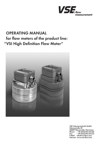
Flow meters with high definition of volume measurementThe preamplifiers of the standard version for flow meters of the “VS” product line output a pulse per tooth gap volume Vz, which corresponds to thevolume measurement Vm (Vm Vz /pulse.). This takes place in two channels,so that you can attain a maximum resolution of 1/4 Vz for the evaluation ofall flanks. A higher resolution is not possible with these preamplifiers.But since as high a resolution as possible is necessary for precise and exactflow and volume measurements, the volume measurement Vm must be resolved even more than is the case with conventional preamplifiers. VSE hastherefore developed the preamplifier with interpolation, with which a selectable resolution of up to 64 flanks (16 pulses) per period can be attained(see table 3). This means that you can resolve the volume measurementVm with this preamplifier to a maximum of 1/64 Vm. For the evaluation, thismeans that a part volume of 1/64 Vm from pulse flank to pulse flank (forquadruple evaluation or flank count) is measured, or a full signal pulse iscounted as part volume of 1/16 Vm (pulse count) (see fig. 3, interpolationVm /16).This individually programmed high resolution enables you to set the volume measurement Vm optimally for each provided case of application.Furthermore, new applications can be availed of with the higher resolutionpotential. Measuring, controlling and regulating in the lower flow rangeMeasuring, controlling and regulating in zero flowMeasuring, controlling and regulating in both flow directionsMeasuring, controlling, dosing and filling of small volumesFlow meters with interpolation electronics (VSI) output two digital signalswith programmable high resolution that are phase-offset 90 (see fig. 3).In addition to the signal emission, a zero signal emission is provided, whichemits a zero signal at each fully registered volume measurement Vm (seefig. 2).1.pulsepulse signal from channel 1 without interpolationpulse signal from channel 2 without interpolationone measurement valueinterpolation factor IPF 8Vm * Vm / 81/2 Vm *1/4 Vm*1234567pulse signal from channel 18pulse signal from channel 21 Vm*Fig. 2 shows the resolution of the volume measurement Vm with an interpolation factor of 8. This resolves each volume measurement into eight individual part volumes. A pulse on the signal output of channel 1 or channel 2 thushas a value of Vm* Vm /8 1/8 Vm per pulse. In double evaluation (flank8360 315 270 225 180 45 33.75 22.5 111.25 135 Division of a single pulse into 360 .All other signal pulses can be regarded in this way.Evaluation electronics recognise flow direction from the channel offset of 90 .Each individual pulse flank is offset 90 and has a value of 1/4 Vm*.10 90 360 270 180 90 0 0 45 zero signal pulse (zero pulse)Fig. 2: Signal emission of the preamplifier with interpolation(interpolation factor 8)evaluation of one channel) this results in a value of 1/2 Vm* Vm /16 1/16 Vm and for quadruple evaluation (flank evaluation of both channels)the result is a value of 1/4 Vm* Vm /32 1/32 Vm per flank. Evaluationelectronics can recognise flow direction from signals offset 90 .
The preamplifier of the “VSI” product line has a programmed interpolationfactor (IPF) with which you can program new, different resolutions. Henceyou can program a resolution of 4 to 64 angular steps (see fig. 4) pervolume measurement Vm . The frequency multiplication “f*” lies between 1and 16 (see table 3).Table 3: Interpolation factor and resolutionInterpolationfactorPulse/VmMax. resolution(evaluation of signalflanks)Resolution Vm*(volume measurement Vm*)[ml]Max. resolution(angle degrees)Frequency fmax*114 (quadrupling)Vm / 490 fmax x 1228Vm / 845 fmax x 23312Vm /1230 fmax x 34416Vm /1622.5 fmax x 45520Vm /2018 fmax x 58832Vm /3211.25 fmax x 8101040Vm /409 fmax x 10121248Vm /487.5 fmax x 12161664Vm /645.625 fmax x 16Only the marked lines are illustrated in the diagram of fig. 3Column 1: Programmable interpolation factor IPF (programmed in the factory).Column 2: Pulses per volume measurement Vm.Column 3: Maximum resolution of the signal flanks. The signal flanks of channels 1 and 2 are evaluated.Column 4: Volume measurement Vm* resulting from the maximum resolution of the signal flanks.Column 5: Maximum resolution in angle degrees at resolution of signal flanks.Column 6: Maximum frequency fmax* at maximum flow Q max and programmed interpolation factor IPFIn practice, the maximum flow Q max of the flow meter is seldom run, so that a lower frequency can be calculated. The maximum frequency is thencalculated according to the following formula:fmax fmax Q max IPFVm(Qmax )*IPFVmFormula 1Maximum frequency of the flow meter signalsMaximum flow attained in the case of application described hereProgrammed interpolation factorVolume measurement of the flow meterExample: Flow meter VSI 1/10 max. flow the system can be run on at a maximumQ max 40 l/min 666.667 ml/sec; IPF 10; Vm 1 ml/pulse; fmax 6666.67 Hz 6.66667 kHzAt max. flowmax 40 l/min, the flow meter VSI 1/10 outputs a frequency of fmax 6666.67 Hz.9
one measurement volume VVmm360 angle degreesVm /1Vm{Vm /2Vm{VmVm /4{1. pulseVm /8Vm{1.Vm /16Vm{1st channel1. pulse2nd channel1. pu ls e1st channel2. pu ls e2nd channel2. pulse3. pulse1st channel4. pulse2nd channel2.3.5.4.6.7.1st channel8.2nd channel1.2.3.4.5.6.7.8.9.10 11 121314 151st channel160 22.5 2nd channel45 90 135 2.22.5 11.25 16.875 1.0 5.625 180 225 270 315 36 0 /0 45 90 135 180 If the resolution is sixteen-fold, this givesa recognition of 22.5 (360 /16)This results in a resolution of 5.625 (22.5 /4)when evaluating the flanks of channel 1 and 2The highest resolution permits recognition ofa measurement volume of 1/64 Vm .Fig. 3: Interpolation of the volume measurement VmAt initial start-up of the system, you have to program the volume measurement Vm* (see table 4, column 4) in your evaluation electronics asparameter value (e.g. multiplier). The evaluation electronics then multiplyevery pulse the flow meter outputs by the volume measurement Vm* andthus calculates the flow and the volume. For flow meters with high resolution, the parameter value volume measurement Vm* is dependent onvolume measurement Vm (see table 4, column 2) and on the programmedinterpolation factor IPF (see table 4, column 3).Please consult this first of all for the volume measurement Vm* and programthis value as parameter into your evaluation electronics.On table 4 you can view the corresponding volume measurement Vm* (seetable 4, column 4) with the real, programmed interpolation factor IPF*(see table 4, column 3). The K-factor in column 5 is a measurement for theresolution per litre.You then get the maximum frequency fmax* (see table 4, column 8) of thesignal pulses for the maximum flow Qmax (see table 4, column 6) with programmed interpolation factor IPF*. This frequency is dependent on the programmed interpolation factor IPF and increases with rising resolution.Important:Test the connected evaluation electronic system as to whether it can process the maximumfrequency fmax* of the flow meter. Check the data from the following table for the relevantflow meter, or calculate the maximum frequency data fmax with formula 1.10
Table 4: Volume measurement and max. frequency at high resolutionFlow meterVol. measurementVmInterpol.IPF*Vol. measurement Vm*(ml/pulse)K-factor*(pulse/l)Q maxfmaxfmax*(Hz)VSI 0.02 0.02 ml/pulse10.0250 0001 666.70.01100 00030.00666667150 0002 l/min( 2 000
consultation and approval of VSE . Flow meter selection the correct selection (version) of type and constructional size is crucial for a trouble-free and safe operation of the flow meters. Owing to the great number of various applications and flow meter versions, the technical specifications in the VSE catalogue material are of a general .