Transcription
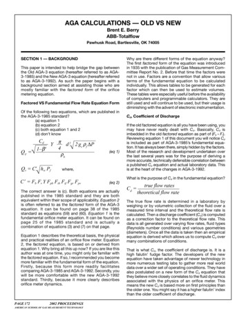
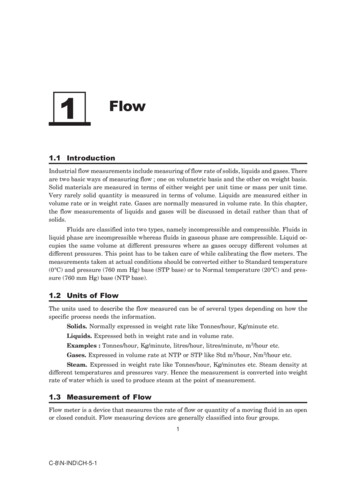
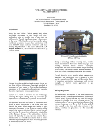
FUNDAMENTALS OF CORIOLIS METERSAGA REPORT NO. 11Stan CalameOil and Gas Business Development ManagerEmerson Process Management - Micro Motion, Inc.7070 Winchester CircleBoulder, CO 80301IntroductionSince the early 1980s, Coriolis meters have gainedworldwide acceptance in gas, liquid, and slurryapplications with an installed base of more than onemillion units. Through significant design, enhancementsin the early 1990s Coriolis meters have rapidly gainedworldwide acceptance in gas phase applications withover 100,000 meters installed worldwide and mostnotably the publication of the second edition of AGAReport Number 11, Measurement of Natural Gas byCoriolis Meter.200mm (8”) Coriolis meter installed in250mm (12”) lineBeing a technology without wearing parts, Coriolismeters are immune to flow factor shift as they age. orated into some Coriolis meter designs allowingflow accuracy verification on-line, without disruption inflow, and without visual inspection of the flow element.Having the ability to bidirectional measure almost anygas from -400 to 660 degrees Fahrenheit with little tono concern of error caused by flow profile disturbances,pulsations, or flow surges, Coriolis meters are becomingthe meter of preference in many applications.Coriolis is a small to medium line-size technology;currently the largest offering from any vendor for gasapplications is a 250mm (10”) equivalent flow diameter.The pressure drop and flow range of a Coriolis meterdraws a direct relationship to the actual flow areathrough the meter. When comparing Coriolis to othermetering technologies; i.e. the flow area trough a turbinemeter is the area not displaced by the turbine internalsand rotor, the flow area of an orifice meter is that of theorifice diameter. Because of this relationship, a Coriolismeter will typically be one pipe size smaller than aturbine meter and several sizes smaller than an orificewhile having similar pressure drops at flowing pressuresin the 300 ANSI class and above.1Overall, Coriolis meters greatly reduce measurementuncertainty and maintenance costs as compared to othergas flow technologies. This paper will discuss the theoryof operation, application, maintenance, and provideexamples of Coriolis meter application in gasmeasurement.Theory of OperationA Coriolis meter is comprised of two main components,a sensor (primary element) and a transmitter (secondary).Coriolis meters directly infer the gas mass flow rate bysensing the Coriolis force on a vibrating tube(s). Theconduit consists of one or more tubes that vibrate at theirresonant frequency by a Drive Coil. Sensing pickoffcoils located on the inlet and outlet sections of thetube(s), oscillate in proportion to the sinusoidalvibration.
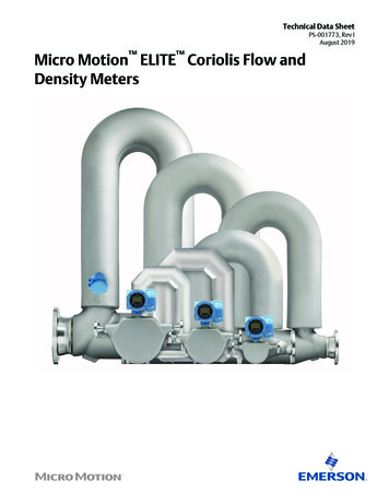
Meter Selection - TemperatureThe typical operating temperature range of Coriolismeters is -400 to 400 degrees Fahrenheit (-240 to 200degrees Celsius). Some advanced designs have extendedthe high temperature operating range up to 660 degreesFahrenheit ( 350 degrees Celsius).Other than temperature compensation for the effect ofYoung’s modulus, flowing temperature measurement isnot required for the measurement of mass, base volume,or energy with Coriolis meters.Coriolis Sensor ComponentsDuring flow, the vibrating tube(s) and gas mass flowcouple together, due to the Coriolis force, causingtwisting of the flow tube(s), from inlet to outlet,producing a phase shift between the signals generated bythe two-pickoff coils. The phase shift or difference intime is directly proportional to mass flow rate.Coriolis Sensing/Pickoff SignalsNote that the vibration frequency of the flow tubes isproportional to the flowing density of the fluid. For gasapplications, the “flowing” or “live” density measuredby the Coriolis meter is not used for gas measurement, asits potential error in relation to gas densities is notacceptable for gas flow measurementpurposes.Although this is the case, density measurement in gasapplications can be used as an indicator of change in aMeter Selection - PressureMost Coriolis meters are designed to operate at pressuresup to 1480 psi (600 ANSI), with meters constructed ofhastalloy and duplex tubes capable of operating atpressures up to 3600 psi (1500 ANSI).Changes in operating pressure can produce a bias oftenreferred to as the “flow pressure effect” that can becompensated for. The "flow pressure effect" of a Coriolismeter is caused by the stiffening of the Coriolis flowtube(s) as the fluid pressure in them increases. Thiseffect is similar to a bicycle inner tube as its internal airpressure is increased; the inner tube is more flexible at alower pressure than at a higher pressure.High fluid pressures cause the flow tube to be moreresistant to the twisting force of the Coriolis Effect thanthey are at low pressures. As the internal flow tube(s)pressure increases, the Coriolis Effect or twisting of theflow tube(s) observed for a given mass flow ratedecreases. Likewise, as the internal pressure decreasesthe Coriolis Effect observed for a given mass flow rateincreases.Every Coriolis meter design and size has a different flowpressure effect specification. To correct for flow pressureeffect the flow pressure effect compensation factordetailed below is applied to the indicated mass flow rate.1Fp 1 ((P P))/100) * (PEffectStaticCalCoriolis meter’s flow factor and/or clean vs. dirty.Coriolis is a direct inferential mass meter eliminating therequirement to quantify gas volumetrically at flowingconditions; i.e. the need to measure flowing temperature,flowing pressure, and calculate aflowingcompressibility. Equations and methods for theconversion of mass to base volume are documented inAGA Report Number 11, Measurement of Natural Gasby Coriolis Meter and AGA Report Number 8,Compressibility Factors for Natural Gas and OtherHydrocarbon Gases.2Where:FpPEffectPStaticPCal Flow pressure effect compensation factor Pressure effect in percent psi Measurement fluid static pressure in psi Calibration static pressure in psiMost Coriolis transmitters have provisions for applyingan average flow pressure effect correction and themonitoring a static pressure transmitter to facilitate livepressure compensation.
Meter Selection - Compressibility, Density, Viscosity,and Reynolds NumberAlthough change in compressibility, density, viscosity,and Reynolds Number are a concern with almost allmetering technologies, the inferred mass flow rate of acurved tube Coriolis meter is insensitive to error causedby these changes.Meter Selection – Rate of ChangeHigh rates-of-change in flow or flow surges are the mostcommon cause of damage in flow meters with rotatingflow elements; e.g. Turbine, Rotary, PositiveDisplacement, etc. High rates of change in flow causethese meters to over-speed and are typically inherent toengine, boiler, and burner fuel gas applications.During a flow surge, the inlet flow splitter of a Coriolismeter chokes flow to the diameter of the flow tubes andthe flowing densities of natural gas mixtures do notprovide enough inertial force to be imparted on the flowtubes to damage them. This coupled with the ability ofadvanced designs to measure up to choke velocitiesremoves any rate-of-change concern in the use ofCoriolis.concerns are application specific, but when present,filtration should be used to protect the meter.Meter Selection - Flow PulsationThe pulsation of flow is typically of high concern in theuse of every flow metering technology. Pulsating flowcan cause measurement error (e.g. fluidic oscillation,orifice/differential head, rotary, turbine, and ultrasonicmeters) and mechanical damage inmeteringtechnologies with load bearings and gears (e.g. rotary,and turbine meters). Flow pulsations are typically aconcern on fuel gas lines to reciprocating engines, theinlet and outlet compression lines of reciprocatingcompressors, and the inlet and outlet lines of regulators.Advancements in Coriolis flow meter design haveyielded designs that maintain accuracy over a wide rangeof pulsating flow conditions. Although Coriolis meters,for the most part, are immune to error caused by fluidpulsations, they are sensitive to pulsations at the resonantfrequency of the meter’s flow tubes. In gas applications,Coriolis meters typically operate at resonant frequenciesabove 100 Hz or 6000 cycles per a minute, where gaspulsations are typically not found.Meter Selection - Over RangeMeter Selection - Gas QualityOver ranging often causes mechanical damage and/orloss of measurement in the use of almost any flow meter.Some Coriolis meter designs can measure gas flow up tosonic velocity or choke point (approximately 1400 ft/secwith natural gas mixtures from atmospheric to 2220 psi)without loss of measurement or damage. Manufacturersshould be consulted on the maximum velocity limit oftheir particular Coriolis meter design.Should debris (i.e. sand, gravel, welding rods, weldingslag) exist that could erode, scar, or plug the flow tubes,filtration should be utilized in the metering systemdesign to protect the meter. Although fine soft particleslike iron oxide, oils, and dust will not damage the flowtubes of a Coriolis meter, build-up of this debris cancause an imbalance in the flow tubes and out ofspecification shift in the meter’s zero. Coriolis metershave high error immunity to dirty processes because anout of specification zero caused by debris buildup willinduce detectable errors only at the low end of a meter’sflow range and are typically insignificant/undetectable atflows in the high end of the flow range.Piping erosion caused by high flow velocities is acommon concern in gas applications. Although thisconcern is valid for carbon steel piping, it is not valid forstainless steel piping or Coriolis meters. For a gas toerode a metal, the metal’s surface must first oxidize andthen high gas velocities erode the soft oxide layer. Inmost gas applications, moisture in the gas causesoxidation of carbon steel piping driving the velocityconcerns of many piping engineers. A Coriolis meter’simmunity to high velocity gas erosion is similar to thatof an orifice plate or sonic nozzle, in that they are madeof stainless steel or other nickel alloys which are highlyimmune to corrosion/oxidation and thus high velocitygas erosion.If abrasive contaminants (sand, welding rods, rocks, etc.)are present in the gas flow stream, erosion or damage ofthe wetted meter components caused by this debristraveling at high flow velocities is of concern. These3In most applications, gas velocities through the flowtubes at the high end of the flow range are typicallysufficient to maintain a meter’s cleanliness. A “ZeroCheck” performed during maintenance will identify ifdebris buildup or coating is affecting the meter’smeasurement accuracy. If an out of tolerance conditionexists, the meter’s zero can be recalibrated to regainaccuracy.Meter Selection - BidirectionalCoriolis meters are bidirectional meters, during flow thesignal from the inlet pick-off coil lags the outlet pick-off
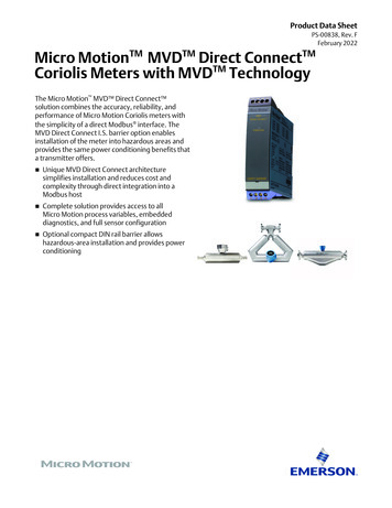
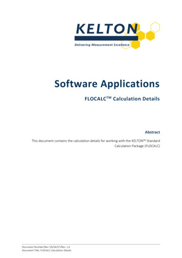
coil signal, by determining which pickoff signal islagging flow direction is determined.Meter Selection - Measurement AccuracyThe measurement accuracy of a Coriolis meter is designand fluid specific. Most bending mode Coriolis meterscan measure gas mixtures at accuracies better than 1%.Some advanced Coriolis designs can achieve accuraciesof /- 0.35%.Meter Selection – Flow RangeThe flow range of a Coriolis meter is determined on thelow end by minimum acceptable accuracy and worstcase drift in a meter’s zero, referred to as “ZeroStability”. Zero Stability is the potential error in allindicated flow rates. Due to this fact, a Coriolis meter’saccuracy naturally improves as mass flow rate increasesuntil a maximum accuracy, dictated by meter design andmeasurement fluid, is reached.The high end of a Coriolis meter’s flow range isdetermined by flow velocity. Most Coriolis meters canmeasure gas velocities up to 200 ft/sec and advanceddesigns can measure gas flow at velocities up to sonicvelocity or choke point without loss of measurement ordamage. Although some Coriolis meter designs canmeasure gas flows up to sonic velocity, a maximumallowable pressure drop dictated by the application inwhich they will be applied typically determinesmaximum flow. This is quite different from traditionalflow technologies where maximum flow is wheremeasurement is lost and/or flow damage occurs to theflow element.Therefore, the appropriate size of Coriolis meter for anapplication is determined by the following. Allowable Pressure Drop @ Maximum FlowMinimum Acceptable Accuracy @ MinimumFlowSince flow through the meter increases with square rootof static pressure change and the minimum flow throughthe meter is constant and relative to the minimumacceptable accuracy, applying a meter at higherpressures, in effect, increases operating range andturndown.4Coriolis Turndown versus Operating PressureIn summary the operating range for a given pressuredrop can be increased by installing a Coriolis meter athigh-pressure locations or upstream of regulation versusdownstream.Meter Selection – Low FlowThe following equation is the most utilized method fordetermining the minimum flow rate of a Coriolis meter.ZeroStabiltyMinFlow Accuracy% /100Since Zero Stability can be expressed in standard volume(scf) units for a given relative density, the minimumstandard volume flow rate at a user specified acceptableaccuracy never changes regardless of pressure ortemperature for a given meter design and size. This isdifferent from other gas measurement technologies werethe minimum flow rate varies with pressure andtemperature.Meter Selection - Maximum flowSome Coriolis meter designs can measure gas flows upto choke point or a flow velocity equivalent to sonicvelocity (Mach 1) of the gas mixture (Approximately1400 ft/sec for natural gas mixtures from atmospheric to2220 psi). Although this is the case, Coriolis aretypically sized within an acceptable pressure drop limitdictated by the application. Utilizing a set of gasreference conditions, often found in the manufacturersspecifications, the following equation can be utilized forcalculating the flow rate through a meter at a givenpressure drop.
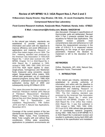
PAppGas f PRe fGas vf QRe fGa sf Ap p Ga s Re fGa s b fInstallation - Meter MountingAp p Ga s QvbAp p Ga sAp p Ga sWhere: PAppGas Maximum allowable pressure dropacross the Coriolis meter with anapplication gas density ( f) in psi f Re fGa sAp p Ga s Density of reference gas at flowingconditions in lb/cf PRe fGas Reference differential pressure across fCoriolis meter with reference gas density( f Re fGa s ) in psiAp p Ga sQvf Re fGa s Density of application gas at flowingconditions in lb/cf Volume flow rate of reference gas atflowing conditions of f Re fGa sand PRe fGas in cf/hr bAp p Ga s Density of application gas at baseQvbconditions in lb/cf Volume flow rate of application gas atAp p Ga sbase conditions in cf/hr or scf/hrInstallation - Electrical ClassificationMost Coriolis meters are designed to meet Class 1,Division 1, and Class 1, Division 2 hazardous areaclassifications.Consideration should be given to the support of thesensor and the aligEnqm.e(6n.t3o)f the inlet and outlet pipingflanges with the sensor. For field fabrication of piping, aspool piece should be used in place of the meter to alignpipe-work prior to welding the Coriolis sensor matingflanges; i.e. slip fit is ideal.Piping should follow typical industry piping codes.Meter performance, specifically meter zero, can beaffected by axial, bending, and torsion stresses. Whenthese stresses exist, pressure, weight, and thermalexpansion effects can amplify them. Although mostCoriolis meters are designed to be relatively immune tothese effects, utilizing properly aligned pipe-work andpiping supports insures the utmost performance of anymeter design and in many cases yields performancebetter than the manufacturer’s specifications.Installation - Meter OrientationCoriolis meters are immune to orientation effects whenmeasuring single-phase fluids, many fluids are rarelyalways in a single phase or free from sporadiccontaminates in the opposite phase. As a rule in gasmeasurement, the Coriolis sensor should be oriented insuch a way as to minimize the possibility of heaviercomponents, like condensate, settling in the sensor flowtube(s). Solids, sediment, plugging, coatings, or trappedliquids can affect the meter performance, especiallywhen present during zeroing of the meter. Allowablesensor orientations will depend on the application andthe geometry of the vibrating flow tube(s). In gasservice, the ideal orientation of the sensor is with theflow tubes in the upright position.Installation – Piping ConfigurationInstallation – Up and Downstream PipingInstallation effects testing performed by SouthwestResearch Institute (SwRI) and sponsored by the GasResearch Institute (GRI) in 2002 confirmed bent tubeCoriolis meters to be mostly immune, within theuncertainty of the flow lab, to upstream installationeffects. The test results can be found in GRI TopicalReport GRI-01/0222.Perturbation testing including pulsation and regulatorvalves placed in close proximity of a bent tube Coriolismeters has also been conducted by other organizationsand independent parties and has shown flowconditioning or straight pipe up and downstream of aCoriolis meter is not required.5Curved or bent tube Coriolis flow sensors are immune tovelocity profile distortion and swirl effects, thusallowing the designer flexibility restricted only by goodpiping support practices to minimize structural stresseson the sensor body.The piping configuration of a Coriolis installation shouldconsist of block valves up and downstream of theCoriolis meter with bleed valves to facilitate purging ofthe piping, zeroing of the meter, and maintenanceprocedures. A bypass should be installed around themeter if interruption of service to the customer is anissue.Although the pressure port for flow pressure effectcompensation has a preferred location upstream of theCoriolis sensor, it can be located up or downstream of
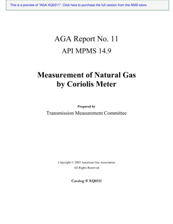
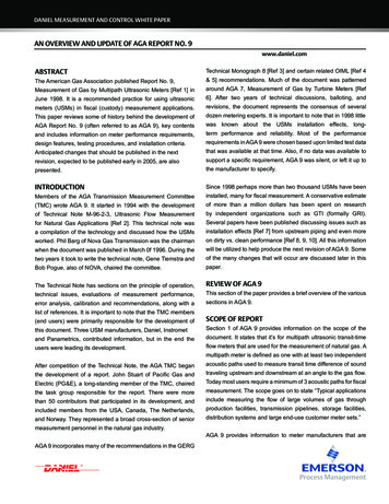
the Coriolis sensor. A temperature port for verificationof the Coriolis sensor’s measured temperature should belocated upstream of the sensor due to the Joule Thomsoneffect at high differential pressures across the sensor.calibration over a water calibration on Coriolis metersintended for gas measurement. Although this is the casethe user should review industry recommended practices,standards, andregulatory requirementswhenestablishing calibration policy for Coriolis.Coriolis meters are an attractive technology when theavailability, capability, or economic viability of gascalibrations is limited. Highly accurate water calibrationsand construction of water calibration facilities areachieved at a fraction the cost of their gas counterparts.Metrology – Volume MeasurementTypical Coriolis Meter InstallationMetrology - CalibrationDue to the variability of manufacturing processes, allCoriolis meters require a flow calibration to adjust theirperformance to the accuracy limits inherent to theirparticular design. As a common practice most Coriolismanufacturers capitalize on the economics and highstability of a water calibration to perform thesecalibrations. Some advanced Coriolis meter designs areimmune to fluid phase, density, and viscosity; enablingwater calibrations to transfer to all other fluids; i.e. gas,liquid, and slurries.Testing by numerous European and North Americanflow labs has confirmed the transferability of watercalibration data on a Coriolis meter to gas applications.Most notably testing sponsored by the Gas ResearchInstitute in 2004 and documented in report GRI-04/172,which covers water to gas transferability and wet gasperformance of Coriolis meters. Conclusions in thereport state, “The single fluid calibration tests show thata water calibration of a Coriolis mass flow meter can beused for natural gas applications without loss ofaccuracy”.GRI 04/0172 Water, Air, and Gas Transferability DataIndustry testing has shown there is minimal benefit, froma calibration uncertainty perspective, in performing a gas6To accurately quantify the mass output of a Coriolismeter applied at pressures other than calibrationpressure, a flow pressure effect correction must beapplied. Every Coriolis meter design and size has adifferent flow pressure effect specification. In order tocorrect for the flow pressure effect in a Coriolis meter’sindicated mass flow rate, the following correction factorshould be applied to the indicated mass output.F p 1 ((P1 P ))/100) * (PStaticCalEffectWhere:FpPEffectPStaticPCal Flow pressure effect compensation factor Pressure effect in percent psi Measurement fluid static pressure in psi Calibration static pressure in psiFor gas applications, the measurement accuracy ofdensity measured by a Coriolis meter is relative to aliquid densitometer’s accuracy, this does not meet theaccuracies required for gas measurement. Therefore theon-line density from the meter is not used for flowmeasurement with gas; rather the relative density or basedensity of the gas is entered into a flow computer asdetermined from either sampling methods or on-line gasanalysis. It should be noted that the gas physical propertyinformation required by AGA8 Gross Method 1, GrossMethod 2, or Detail Method and procedural methods forapplying this information in the use of a Coriolis meterare identical to those required by volumetric meters; i.e.Turbine, Orifice, Rotary, and Ultrasonic. Coriolistechnology uses the following calculations to output ahighly accurate standard or normal volumetric output.SCF (gas) Mass(gas) F b(Gas) pSCFp Mass(gas)F
Gr7x (Gas)(gas)b( Air )
b Pb x MrZb x R x TbWhere:SCF( gas) Gas volume at Tb and PbMass Weight of gas (Coriolis output) b Density at Tb and PbTb Temperature at base conditionsPb Pressure at base conditionsZb Compressibility at base conditions ( TbandPb )Gr(Ga s) Real Gravity at Tb andRMrFp Universal gas constant Molar WeightPb Flow pressure effect compensation factorwill affect a Coriolis meter’s accuracy more at low flowsthan at high flows. If the buildup is causing a shift in themeter zero, cleaning and re-zeroing will bring themeter’s performance back to its original specification. Atany given level of coating, if the coating is stable, themeter can be re-zeroed, without cleaning, and meterperformance can be restored. If coating of the sensorcontinues, the zero may continue to drift.Inspection and Re-zeroingTo inspect or re-zero a Coriolis meter, thermalequilibrium of the meter should be established. Flowingat a flow rate above the transitional flow rate can be usedto establish thermal equilibrium. Once thermalequilibrium is achieved the meter is to be blocked in andthe meter’s zero verified. Even though the stream is notflowing, the flow meter may indicate a small amount offlow bias, either positive or negative. Causes for a biasin the zero are usually related to the differences betweenprevious and current zero flow conditions, whichinclude. Field Maintenance and Meter VerificationThe field maintenance of a Coriolis meter is aninspection process consisting of the following1)2)3)4)Transmitter VerificationSensor VerificationSensor Temperature VerificationSensor Zero VerificationAGA11 states the user should use meter verification datato guide them on the need to re-zero the Coriolis meterand when to flow test.Field Maintenance – Zero VerificationThe meter zero should be verified periodically andrecalibrated if it is not within the manufacturer’sspecification. At a minimum, inspection of the meterszero should be performed seasonally in the first year ofoperation to identify and installation or process conditionissues. After the first year of operation, zero verificationintervals can be extended based on the historicperformance of the meter’s zero for the application.Drift in Zero ReadingProduct buildup, erosion, or corrosion will affect themeter zero performance. Product buildup (coating) maybias the meter zero. It should be noted that a zero shift8Differences between the calibration mediadensity and the gas densityDifferences in temperatureThe meter should read a mass flow rate that is less thanthe manufacturer is zero stability specification under theno-flow condition.If the zero is within specification re-zeroing the meter isunwarranted. If outside of specification the current zerovalue and meter temperature should be recorded forfuture reference and the zeroing procedure specified bythe meter manufacturer should be followed.Field Maintenance – DiagnosticsDiagnostic LED(s) and display are typically provided toindicate the operating status of the sensor andtransmitter. The diagnostics of the Coriolis transmitterverify the integrity of the CPU and insure operationalparameters are within tolerance. Coriolis sensordiagnostics verify the sensing components of the sensorare not damaged and operating within normal limits.Sensor diagnostics also provide insight into the processflow conditions and potential measurement problemswith them.Some Coriolis sensor designs also provide on-lineverification of the flow tube(s) structure. The flow tubestructure of a Coriolis sensor dictates its flow calibrationfactor. This method of verification measures flow tube(s)stiffness to infer density and mass calibration factor asunchanged. Utilizing resonant modal analysis techniquesthe transmitter actively tests the flow tube(s) stiffness
during flowing conditions and determines if an out oftolerance stiffness change has occurred.Coriolis meter verification by resonant modal analysismethod is a significant advancement in Coriolistechnology. This capability allows for verification aCoriolis meter’s accuracy without interruption in flow orinspection of the meter’s components for damage. Coriolis technology reduces or eliminates several of theoperating expenditures associated with gas flowtechnologies. Typical operating expenditures that arereduced or eliminated are as follows. CAPEXCapital Expenditures (“CAPEX”) to implement Coriolismeasurement will vary dependent upon meter design,size, pressure ratings, materials of construction, andaccuracy. Typical capital expenditures required in theimplementation of a Coriolis metering system includethe following. Coriolis SensorFlow Computer or TransmitterPower SystemInstallation and Startup Coriolis technology reduces or eliminates several of thecapital expenditures required in the application of othergas flow technologies and typically associated withnatural gas metering. Typical capital expenditures thatare reduced or eliminated are as follows. Pressure measurement - Typically not requiredfor flow measurement and if required, a highaccuracy transmitter is unwarrantedTemperature measurement - Integral to Coriolissensor designSpecialty upstream and downstream pipingand/or flow conditioning – Not requiredGas flow calibration of sensor - Factory waterflow calibration transfers to natural gasmeasurementInstallation and startup Operating Expenditures (“OPEX”) to maintain Coriolismeasurement will vary dependent upon meter design,power system, cleanliness of process, and verificationprocedures required by meter design, adopted by theuser’s organization, or dictated by regulatoryrequirements. Typical operating expenditures required inthe use a Coriolis metering system include the following. 8Routine verification/inspection of sensor zeroand meter diagnosticsPressure calibration – Although pressuremeasurement, if used, will require periodicverification its recalibration with a precisionreference is typically not required.TemperaturemeasurementAlthoughtemperature measurement will require periodicverification its recalibration with a precisionreference is typically not requiredInspection and cleaning of specialty upstreamanddownstream pipingand/orflowconditioningValidation of flow factor - Coriolis meters canbe validated with water flow references, whichare typically more economical than that of theirnatural gas counterparts. Some Coriolis designsincorporate structural integrity diagnostics thatverify the sensor’s flow factor or identify therequirement for recalibration. Structuraldiagnostics eliminate unnecessary flowvalidations or recalibrations.Application ExamplesCoriolis meters are applied in a wide variety ofapplications, from the “wellhead to the burner tip”.Coriolis meters are primarily a smaller to medium linesize meter, ideally suited to the following gas metering“sweet spots”: OPEXThe replacement of battery backup power cells,if used, when their efficiency has declined. Line sizes 250mm (12”) and smaller300 ANSI through 900 ANSIHigh turndown requirementsDirty, wet, or sour gas where maintenance canbe an issue with other technologiesThere is no room for long straight-runsChanging gas composition and densitySudden changes in gas flow velocity (fuel andproduction gas applications)Pulsating gas flows (fuel gas and compressiongas in the use of reciprocating compressors)Applications were abnormally high flow ratescan occur.Coriolis meters can be sized for very low-pressure drop(100” H2O), but can also be installed upstream of thepressure regulator with high-pressure drops for increasedturndown without concern of damage or malfunction dueto flow noise. For instance, in one application forcustody transfer of nitrogen, a 50-psid drop (1390” H2O)
was allowed across the Coriolis meter and the pressureregulator adjusted accordingly. This allowed the use of a1” Coriolis meter instead of a 3” meter downstream ofthe regulator and a 40:1 useable turndown (Better than1% accuracy at minimum flow and an average 0.35%base volume accuracy over 95% of the upper flowrange).Separator gas: Saudi Aramco uses a number of Coriolismeters on both the liquid and gas side of separators.This application is of particular note because
flow elements; e.g. Turbine, Rotary, Positive Displacement, etc. High rates of change in flow cause these meters to over-speed and are typically inherent to engine, boiler, and burner fuel gas applications. y During a flow surge, the inlet flow splitter of a Coriolis meter chokes flow to the diameter of the flow tubes and