Transcription
UM2220User manualGetting started with MotionFX sensor fusion library in X-CUBE-MEMS1expansion for STM32CubeIntroductionThe MotionFX is a middleware library component of the X-CUBE-MEMS1 software and runs on STM32. It provides real-timemotion-sensor data fusion. It also performs gyroscope bias and magnetometer hard iron calibration.This library is intended to work with ST MEMS only.The algorithm is provided in static library format and is designed to be used on STM32 microcontrollers based on the ARM Cortex -M0 , ARM Cortex -M3, ARM Cortex -M4 or ARM Cortex -M7 architectures.It is built on top of STM32Cube software technology to ease portability across different STM32 microcontrollers.The software comes with sample implementation running on an X-NUCLEO-IKS01A2, X-NUCLEO-IKS01A3 or X-NUCLEOIKS02A1 expansion board on a NUCLEO-F401RE, NUCLEO-L476RG, NUCLEO-L152RE or NUCLEO-L073RZ developmentboard.UM2220 - Rev 8 - April 2021For further information contact your local STMicroelectronics sales office.www.st.com
UM2220Acronyms and abbreviations1Acronyms and abbreviationsTable 1. List of acronymsAcronymUM2220 - Rev 8DescriptionAPIApplication programming interfaceBSPBoard support packageGUIGraphical user interfaceHALHardware abstraction layerIDEIntegrated development environmentpage 2/25
UM2220MotionFX middleware library in X-CUBE-MEMS1 software expansion for STM32Cube2MotionFX middleware library in X-CUBE-MEMS1 softwareexpansion for STM32Cube2.1MotionFX overviewThe MotionFX library expands the functionality of the X-CUBE-MEMS1 software.The library acquires data from the accelerometer, gyroscope (6-axis fusion) and magnetometer (9-axis fusion)and provides real-time motion-sensor data fusion.The MotionFX filtering and predictive software uses advanced algorithms to intelligently integrate outputs frommultiple MEMS sensors, regardless of environmental conditions, for an optimum performance.The library is designed for ST MEMS only. Functionality and performance when using other MEMS sensors arenot analyzed and can be significantly different from what described in the document.The complexity of the library dedicated to the Cortex-M0 core is reduced due to the performance limitation ofCortex-M0 architecture. This library uses different APIs and has less features in comparison with the version forCortex-M3, Cortex-M4 and Cortex-M7 (for further details, see the following chapters).A sample implementation is available on X-NUCLEO-IKS01A2 and X-NUCLEO-IKS01A3 expansion board,mounted on a NUCLEO-F401RE, NUCLEO-L476RG, NUCLEO-L152RE or NUCLEO-L073RZ developmentboard.2.2MotionFX libraryTechnical information fully describing the functions and parameters of the MotionFX APIs can be found in theMotionFX Package.chm compiled HTML file located in the Documentation folder.2.2.1MotionFX library descriptionThe MotionFX sensor fusion library manages data acquired from accelerometer, gyroscope and magnetometersensor; it features: real-time 9-axis motion-sensor data fusion (accelerometer, gyroscope, magnetometer) real-time 6-axis motion-sensor data fusion (accelerometer, gyroscope) computation of rotation, quaternions, gravity and linear acceleration data gyroscope bias calibration magnetometer hard iron calibration recommended sensor data sampling frequency of 100 Hz resources requirements:–Cortex-M0 : 15.9 kB of code and 2.1 kB of data memory–Cortex-M3: 49.3 kB of code and 1.1 kB of data memory–Cortex-M4: 44.1 kB of code and 1.1 kB of data memory–Cortex-M7: 42.6 kB of code and 1.1 kB of data memory available for ARM Cortex-M0 , Cortex-M3, Cortex-M4 and Cortex-M7 architecture2.2.2MotionFX 6-axis and 9-axis sensor fusion modesThe MotionFX library implements a sensor fusion algorithm for the estimation of 3D orientation in space. It usesa digital filter based on the Kalman theory to fuse data from several sensors and compensate for limitations ofsingle sensors. For instance, gyroscope data can drift and this impacts the orientation estimation; this issue canbe fixed by using the magnetometer to provide absolute orientation information.Similarly, the magnetometer does not have a very high bandwidth and suffers from magnetic disturbance, butthese weaknesses can be compensated with a gyroscope.9-axis sensor fusion uses data from the accelerometer, gyroscope and magnetometer and provides absoluteorientation in 3D space including heading (i.e., the magnetic North direction).6-axis sensor fusion uses the accelerometer and gyroscope data only. It has lower computational requirements,but does not provide information about the device absolute orientation.6-axis sensor fusion is fit for fast movements (e.g., for gaming) and when absolute orientation is not necessary.UM2220 - Rev 8page 3/25
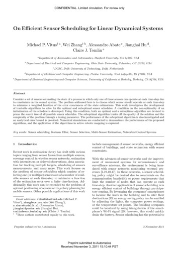
UM2220MotionFX library2.2.3MotionFX library operationThe MotionFX library integrates 6- and 9-axis sensor fusion algorithms in one library; they can even runsimultaneously to provide both rotation vector (9X) and game rotation vector (6X).Cortex-M3, Cortex-M4 and Cortex-M7The library implements the following critical internal functions associated with sensor fusion computation:1.the MotionFX propagate is a prediction function used to estimate the orientation in 3D space; gyroscopedata is given more weight in this phase.2.the MotionFX update is the corrective function which adjusts the predicted value when necessary;accelerometer and magnetometer data are given more weight in this phase.The MotionFX update function can be called whenever the MotionFX propagate is invoked, or less often insystems that have less computation power.The MotionFX update function takes approximately three times more MCU computation time than theMotionFX propagate function.Cortex-M0 The sensor fusion computation is concentrated in only one function MotionFX CM0P update.2.2.4MotionFX library parametersCortex-M3, Cortex-M4 and Cortex-M7The library is "parametrized" using an MFX knobs t structure.The parameters for the structure are: ATime, MTime, FrTime represent the weighting stability of sensors for prediction (trust factor), from 0 to 1.Default values are recommended.–ATime: lowering the value will increase the accelerometer weight and sensitivity towards externalacceleration. If the application experiences low acceleration ( 1g) most of time, it is recommended toincrease the value.–MTime, FrTime: for 9X solution, the lower value will increase the weight of magnetometer reading.If the application experiences low magnetic interference ( 50 μT) most of time, it is recommended toincrease the value. LMode represents the gyroscope bias learning mode; the library automatically tracks and calibrates gyrozero-rate bias drift.This possible parameter values are:–LMode 0 – learning off; use this mode if the gyro is already calibrated–LMode 1 – static learning; learning is performed only when the system is not moving–LMode 2 – dynamic learning; learning is also performed when the system is moving gbias acc/gyro/mag th sc represents the thresholds below which the gbias algorithm automaticallystarts. These values should be established through testing (they are different for different part numbers).The values in the example project are usually correct. The value can be determined by enablingstart automatic gbias calculation, placing the device stationary for 10 seconds and reading thevalue of knobs.–modx represents the decimation of MotionFX update call frequency–output type represents the sensor fusion library output orientation: 0 NED, 1 ENU–start automatic gbias calculation: this flag allows computing gbias acc/gyr/mag sens th sc for an application, by placing the device stationary for 10 seconds and setting thisflag to 1 by calling MotionFX setKnobs API. After 10 seconds or more, call MotionFX getKnobsAPI to get the value of these thresholds.acc/gyro/mag orientation is the acc/gyro/mag data orientation string of three charactersindicating the direction of each positive orientation of the reference frame used for the accelerometerdata output, in the sequence x, y, z. Valid values are: n (north) or s (south), w (west) or e (east), u (up)or d (down).As shown in the figure below, the X-NUCLEO-IKS01A2 accelerometer sensor has an NWU orientation(x - East, y - North, z - Up), so the string is: “nwu”.–UM2220 - Rev 8page 4/25
UM2220MotionFX libraryFigure 1. Example of sensor orientationsCortex-M0 Only the sensor orientation must be set using MotionFX CM0P setOrientation function. The parameters ofthis function are orientation strings which are composed in the same manner as for Cortex-M3, Cortex-M4 andCortex-M7 (see above).The MotionFX propagate and the MotionFX update (MotionFX CM0P update) functions receive inputfrom sensors in the MFX input t (MFX CM0P input t) structure: mag represents magnetometer data after calibration in μT/50 acc represents accelerometer data in g gyro represents gyroscope data in dpsThe MotionFX propagate and the MotionFX update (MotionFX CM0P update) functions provide thesensor fusion output in the MFX output t (MFX CM0P output t) structure: UM2220 - Rev 8rotation represents the system orientation in three-angle format: yaw, pitch and rollMotionFX library uses the following convention yaw range: 0-360 degrees, pitch range 180 degrees and rollrange 90 degreesquaternion represents the system orientation in four-number format; this format gives the sameinformation as rotation but it has advantages for computation and is therefore usually used by otheralgorithms (based on the sensor fusion)gravity represents the static acceleration (i.e., Earth gravity) vector extracted from the acceleration datalinear acceleration represents the dynamic acceleration (i.e., movement) vector extracted from theacceleration datapage 5/25
UM2220MotionFX library 2.2.5heading represents the heading of the device in degrees. Heading 0 degree represents the magnetic Northdirection for 9-axis sensor fusion, while, for 6-axis sensor fusion, it represents heading of device at thealgorithm start.headingErr represents the heading error of the device in degreesMotionFX library output data rateIt is important to set up the sensor fusion library output data rate properly; 100 Hz is recommended.The output data rate for: the gyroscope and the accelerometer should be equal to or greater than 100 Hz; the magnetometer can be lower - 20/40 Hz is typically good for a magnetic field sensor.Cortex-M3, Cortex-M4 and Cortex-M7It is possible to scale the library system requirements in terms of MCU/MPU load. As the MotionFX updatefunction requires approximately three times more computation power than the MotionFX propagate function,it can be called at a lower frequency than the library output data rate if the system resources are limited (e.g., inembedded systems).Use the modx parameter in MFX knobs t structure to decrease the frequency of MotionFX updatefunction calls. For example, setting modx to 2 calls the MotionFX update function once every twoMotionFX propagate function calls.The recommended settings are: modx 1, for tablets or other systems with MCU/MPU and for STM32F4; 2.2.6modx 2, for STM32F1.Sensor calibration in the MotionFX libraryGyroscope and accelerometer calibrationAccelerometer calibration is not necessary for sensor fusion except for applications demanding very highorientation precision; it involves aligning the system in several positions according to the gravity direction.Gyroscope calibration is handled automatically by the MotionFX library by continuously compensating the zerorate offset effect.Magnetometer calibrationThe MotionFX library contains routines for magnetometer hard iron calibration.The magnetometer is affected by the hard-iron and soft-iron phenomena described below.Hard-iron distortionHard-iron distortion is normally generated by ferromagnetic material with permanent magnetic fields that are partof the object (e.g., a tablet) in use. These materials can be permanent magnets or magnetized iron or steel. Theyare time invariant and deform the local geomagnetic field with different offsets in different directions.As each board can be magnetized differently, the hard iron effect is specific to the individual board.If you move the board around a space approximating (as much as possible) a 3D sphere in an ideal environment(no hard-iron/soft-iron distortion) and plot the collected magnetic sensor raw data, the result is a perfect spherewith no offset.The hard-iron distortion effect offsets the sphere along the x, y and z axes; in the x-y plane, the hard-irondistortion is identified by an offset of the origin of the ideal circle from (0, 0), scatter plots for XY and XZ axes aresufficient to determine if there is an offset.Soft-iron distortionSoft-iron distortion is generated by magnetically soft materials or current carrying PCB traces. While hard-irondistortion is constant regardless of the orientation, the soft-iron distortion changes with the orientation of theobject in the Earth’s field (soft magnetic materials change their magnetization direction).The local geomagnetic field is deformed with different gain on different directions. The effect of the soft-iron todistort the ideal full round sphere into a tilted ellipsoid; in the x-y plane, the soft-iron distortion is identified by atilted ellipse with the origin at (0,0) for the XY axis (XZ).UM2220 - Rev 8page 6/25
UM2220MotionFX libraryThe soft iron effect is the same across all boards of the same design, which is why a good PCB design whichtakes magnetometer placement (high current traces/other component clearance) into account can generally avoidany soft iron effects (valid for X-NUCLEO-IKS01A2 expansion board).Calibration procedureThe MotionFX library magnetometer calibration library compensates for hard-iron distortions.The magnetometer calibration can be performed at a slower frequency than the sensor fusion output data rate(e.g., 25 Hz).To run the calibration:1.initialize magnetometer calibration library (MotionFX MagCal init or MotionFX CM0P MagCal init)2.3.call periodically calibration function (MotionFX MagCal run or MotionFX CM0P MagCal run) until thecalibration is successfully performedcheck if calibration was successful (MotionFX MagCal getParams orMotionFX CM0P MagCal getParams); if the function returns mag data out.cal quality MFX MAGCALGOOD or MFX CM0P CALQSTATUSBEST, the calibration was successfully performed4.apply calibration results:– MAG Calibrated.AXIS X MAG Value.AXIS X - MAG Offset.AXIS X– MAG Calibrated.AXIS Y MAG Value.AXIS Y - MAG Offset.AXIS Y– MAG Calibrated.AXIS Z MAG Value.AXIS Z - MAG Offset.AXIS ZAfter calibration routine initialization, slowly rotate the device in a figure 8 pattern in space. While performingthis movement, keep the device clear of other magnetic objects such as cell phones, computers and other steelobjects.Figure 2. STM32 Nucleo board rotation during calibrationTo check that the calibration was performed correctly, check magnetometer data (after applying calibration results)using the scatter plot.UM2220 - Rev 8page 7/25
UM2220MotionFX library2.2.7MotionFX APIsThe MotionFX APIs are:Cortex-M3, Cortex-M4 and Cortex-M7 size t MotionFX GetStateSize(void)–– void MotionFX initialize(MFXState t mfxstate pt)––Note:performs MotionFX library initialization and setup of the internal mechanismmfxstate pt is the pointer to the allocated memory for the instance of MotionFXThis function must be called before using the sensor fusion library and the CRC module in the STM32microcontroller (in RCC peripheral clock enable register) has to be enabled. uint8 t MotionFX GetLibVersion(char *version)––retrieves the version of the library*version is a pointer to an array of 35 characters–returns the number of characters in the version stringvoid MotionFX setKnobs(MFXState t mfxstate pt, MFX knobs t *knobs)–– UM2220 - Rev 8retrieves the size of the library to be allocated prior to runevery instance of motionFX requires the allocation of this sizesets the internal knobsmfxstate pt is a pointer to the allocated memory for the instance of MotionFXvoid MotionFX getKnobs(MFXState t mfxstate pt, MFX knobs t *knobs)––gets the current internal knobsmfxstate pt is a pointer to the allocated memory for the instance of MotionFX–*knobs parameter is a pointer to a structure with knobsMFX engine state t MotionFX getStatus 6X(MFXState t mfxstate pt)––gets the 6 axes library statusmfxstate pt is a pointer to the allocated memory for the instance of MotionFX–returns 1 if enabled, 0 if disabledMFX engine state t MotionFX getStatus 9X(MFXState t mfxstate pt)––gets the 9 axes library statusmfxstate pt is a pointer to the allocated memory for the instance of MotionFX–returns 1 if enabled, 0 if disabledvoid MotionFX enable 6X(MFXState t mfxstate pt, MFX engine state t enable)––enables or disables the 6 axes function (ACC GYRO)mfxstate pt is a pointer to the allocated memory for the instance of MotionFX–enable parameter is 1 to enable, 0 to disablevoid MotionFX enable 9X(MFXState t mfxstate pt, MFX engine state t enable)––enables or disables the 9 axes function (ACC GYRO MAG)mfxstate pt is a pointer to the allocated memory for the instance of MotionFX–enable parameter is 1 to enable, 0 to disablepage 8/25
UM2220MotionFX library UM2220 - Rev 8void MotionFX setGbias(MFXState t mfxstate pt, float *gbias)––sets the initial gbiasmfxstate pt is a pointer to the allocated memory for the instance of MotionFX–*gbias parameter is a pointer to a float array containing the gyro bias value for each axisvoid MotionFX getGbias(MFXState t mfxstate pt, float *gbias)––gets the initial gbiasmfxstate pt is a pointer to the allocated memory for the instance of MotionFX–*gbias parameter is a pointer to a float array containing the gyro bias value for each axisvoid MotionFX update(MFXState t mfxstate pt, MFX output t *data out, MFX input t*data in, float *eml deltatime, float *eml q update)––runs the Kalman filter updatemfxstate pt is a pointer to the allocated memory for the instance of MotionFX–*data out parameter is a pointer to output data structure–*data in parameter is a pointer to input data structure–*eml deltatime parameter is a pointer to delta time between two propagate calls [sec]–*eml q update parameter is a pointer set to NULLvoid MotionFX propagate(MFXState t mfxstate pt, MFX output t *data out,MFX input t *data in, float *eml deltatime––runs the Kalman filter propagatemfxstate pt is a pointer to the allocated memory for the instance of MotionFX–*data out parameter is a pointer to output data structure–*data in parameter is a pointer to input data structure–*eml deltatime parameter is a pointer to delta time between two propagate calls [sec]void MotionFX MagCal init(int sampletime, unsigned short int enable)––initializes the magnetometer calibration librarysampletime parameter is a period in milliseconds [ms] between the update function calls–enable parameter is to enable (1) or disable (0) libraryvoid MotionFX MagCal run(MFX MagCal input t *data in)––runs the magnetometer calibration algorithm*data in parameter is a pointer to input data structure–the parameters for the structure type MFX MagCal input t are: mag is uncalibrated magnetometer data [µT]/50 time stamp is the timestamp [ms]void MotionFX MagCal getParams(MFX MagCal output t *data out)––gets magnetometer calibration parameters*data out parameter is a pointer to output data structure–the parameters for the structure type MFX MagCal output t are: hi bias is the hard iron offset array [µT]/50 cal quality is the calibration quality factor: MFX MAGCALUNKNOWN 0; accuracy of the calibration parameters is unknown MFX MAGCALPOOR 1; accuracy of the calibration parameters is poor, cannot be trusted MFX MAGCALOK 2; accuracy of the calibration parameters is OK MFX MAGCALGOOD 3; accuracy of the calibration parameters is goodpage 9/25
UM2220MotionFX libraryStoring and loading magnetometer calibration parametersThe following functions have to be implemented specifically for each target platform: char MotionFX LoadMagCalFromNVM(unsigned short int dataSize, unsigned int *data)– –the function is used to retrieve the calibration parameters from storage, the function is called whenmagnetometer calibration library is enableddataSize is the size of the data in bytes–*data is the data location pointer–returns 0 for correct loading, 1 otherwisechar MotionFX SaveMagCalInNVM(unsigned short int dataSize, unsigned int *data)––the function is used to store the calibration parameters and is called when the magnetometercalibration library is disableddataSize is the size of the data in bytes–*data is the data location pointer–returns 0 for correct saving, 1 otherwiseCortex-M0 uint8 t MotionFX CM0P GetLibVersion(char *version)––retrieves the version of the library*version is a pointer to an array of 35 characters–returns the number of characters in the version stringvoid MotionFX CM0P Initialize(MFX CM0P mcu type t mcu type)––Note: MFX CM0P MCU STM32 is a standard STM32 MCU MFX CM0P MCU BLUE NRG1 is BlueNRG-1 MFX CM0P MCU BLUE NRG2 is BlueNRG-2 MFX CM0P MCU BLUE NRG LP is BlueNRG -LPThis function must be called before using the sensor fusion library and the CRC module in the STM32microcontroller (in RCC peripheral clock enable register) has to be enabled. void MotionFX CM0P setOrientation(const char acc orientation[4], const chargyro orientation[4], const char mag orientation[4])–– gets the 6 axes library statusreturns 1 if enabled, 0 if disabledMFX CM0P engine state t MotionFX CM0P getStatus 9X(void)–– sets sensors orientationacc orienation/gyro orientation/mag orientation orientation stringsMFX CM0P engine state t MotionFX CM0P getStatus 6X(void)––gets the 9 axes library statusreturns 1 if enabled, 0 if disabledMFX CM0P engine state t MotionFX CM0P getStatus euler(void)––UM2220 - Rev 8performs MotionFX library initialization and setup of the internal mechanismmcu type is the type of MCU:gets the status of euler angles calculationreturns 1 if enabled, 0 if disabledpage 10/25
UM2220MotionFX library MFX CM0P engine state t MotionFX CM0P getStatus gbias(void)–– void MotionFX CM0P enable 6X(MFX CM0P engine state t enable)–– sets the initial gbias*gbias parameter is a pointer to a float array containing the gyro bias value for each axisvoid MotionFX CM0P getGbias(float *gbias)–– enables or disables the gyroscope calibrationenable parameter is 1 to enable, 0 to disablevoid MotionFX CM0P setGbias(float *gbias)–– enables or disables the euler angles calculationenable parameter is 1 to enable, 0 to disablevoid MotionFX CM0P enable gbias(MFX CM0P engine state t enable)–– enables or disables the 9 axes function (ACC GYRO MAG)enable parameter is 1 to enable, 0 to disablevoid MotionFX CM0P enable euler(MFX CM0P engine state t enable)–– enables or disables the 6 axes function (ACC GYRO)enable parameter is 1 to enable, 0 to disablevoid MotionFX CM0P enable 9X(MFX CM0P engine state t enable)–– gets the status of gyroscope calibrationreturns 1 if enabled, 0 if disabledgets the initial gbias*gbias parameter is a pointer to a float array containing the gyro bias value for each axisvoid MotionFX CM0P update(MFX CM0P output t *data out, MFX CM0P input t*data in, float deltatime)––runs the sensor fusion algorithm*data out parameter is a pointer to output data structure–*data in parameter is a pointer to input data structure–deltatime parameter is a delta time between two propagate calls [sec]void MotionFX CM0P MagCal init(int sampletime, unsigned short int enable)––initializes the magnetometer calibration librarysampletime parameter is a period in milliseconds [ms] between the update function calls–enable parameter is to enable (1) or disable (0) libraryvoid MotionFX CM0P MagCal run(MFX MagCal CM0P input t *data in)––runs the magnetometer calibration algorithm*data in parameter is a pointer to input data structure–the parameters for the structure type MFX MagCal CM0P input t are: UM2220 - Rev 8mag is uncalibrated magnetometer data [µT/50]page 11/25
UM2220MotionFX library UM2220 - Rev 8void MotionFX CM0P MagCal getParams(MFX CM0P MagCal output t *data out)––gets magnetometer calibration parameters*data out parameter is a pointer to output data structure–the parameters for the structure type MFX CM0P MagCal output t are: hi bias is the hard iron offset array [µT/50] cal quality is the calibration quality factor: MFX CM0P MAGCALUNKNOWN 0; accuracy of the calibration parameters is unknown MFX CM0P MAGCALPOOR 1; accuracy of the calibration parameters is poor, cannot betrustedMFX CM0P MAGCALOK 2; accuracy of the calibration parameters is OK MFX CM0P MAGCALGOOD 3; accuracy of the calibration parameters is goodpage 12/25
UM2220MotionFX library2.2.8API flow chartFigure 3. MotionFX API logic obsMagCal InitWait Expiring TimerData Read InterruptRead Acc Gyr Mag DataMagCal run / MagCal getParamsPropagateUpdateGet MotionFX Outputs2.2.9Demo codeThe following demonstration code reads data from the accelerometer, gyroscope and magnetometer sensors andgets the rotation, quaternions, gravity and linear acceleration.UM2220 - Rev 8page 13/25
UM2220MotionFX library#define MFX STR LENG#define STATE SIZE#define ENABLE 6X35(size t)(2450)0[.]/*** Initialization ***/char lib version[MFX STR LENG];static uint8 t mfxstate[STATE SIZE];MFX knobs t iKnobs;float LastTime;/* Check if statically allocated memory size is sufficientto store MotionFX algorithm state and resize if necessary */if (STATE SIZE MotionFX GetStateSize())Error Handler();/* Sensor Fusion API initialization function */MotionFX initialize((MFXState t *)mfxstate);/* Optional: Get version */MotionFX GetLibVersion(lib version);/* Modify knobs settings & set the knobs */MotionFX getKnobs(mfxstate, &iKnobs);[.]MotionFX setKnobs(mfxstate, &iKnobs);MotionFX enable 6X(mfxstate, MFX ENGINE DISABLE);MotionFX enable 9X(mfxstate, MFX ENGINE DISABLE);/* Enable 9-axis sensor fusion */if (ENABLE 6X 1){MotionFX enable 6X(mfxstate, MFX ENGINE ENABLE);}else{MotionFX enable 9X(mfxstate, MFX ENGINE ENABLE);}[.]/*** Using Sensor Fusion algorithm ***/Timer OR DataRate Interrupt Handler(){MFX input t data in;MFX output t data out;float dT;float *q; /* Quaternion pointer to either to Game Rotation or Rotation vector (4 length) *//* Get acceleration X/Y/Z in g */MEMS Read AccValue(data in.acc[0], data in.acc[1], data in.acc[2]);/* Get angular rate X/Y/Z in dps */MEMS Read GyroValue(data in.gyro[0], data in.gyro[1], data in.gyro[2]);/* Get magnetic field X/Y/Z in uT/50 */MEMS Read MagValue(data in.mag[0], data in.mag[1], &data in.mag[2]);UM2220 - Rev 8page 14/25
UM2220Sample application/* Calculate elapsed time from last accesing this function in seconds */dT CurrentTime - LastTime;LastTime CurrentTime;/* Run Sensor Fusion algorithm */MotionFX propagate(mfxstate, data out, data in, &delta time);MotionFX update(mfxstate, data out, data in, &delta time, NULL);if (ENABLE 6X 1){q data out.quaternion; /* Game rotation Vector */}else{q data out.quaternion; /* Rotation Vector in 9X */}}2.2.10Algorithm performanceTable 2. Cortex-M4 and Cortex-M3: elapsed time (µs) algorithmCortex-M4 STM32F401RE at 84 MHzSTM32CubeIDE1.2.0IAR EWARM8.32.3Cortex-M3 STM32L152RE at 32 MHzKeil µVision 5.27STM32CubeIDE1.2.0IAR EWARM 8.32.3Keil µVision inAvgMax 118851943 112351926 120112059168232421333893241091470714213Table 3. Cortex-M0 and Cortex-M7: elapsed time (µs) algorithmCortex-M0 STM32L073RZ at 32 MHzSTM32CubeIDE1.2.02.3IAR EWARM8.32.3Cortex-M7 STM32F767ZI at 96 MHzKeil µVision 5.27STM32CubeIDE1.2.0IAR EWARM 8.32.3Keil µVision 841128402881Sample applicationThe MotionFX middleware can be easily manipulated to build user applications. A sample application is providedin the Application folder.It is designed to run on a NUCLEO-F401RE, NUCLEO-L476RG, NUCLEO-L152RE or NUCLEO-L073RZdevelopment board connected to an X-NUCLEO-IKS01A2, X-NUCLEO-IKS01A3 or X-NUCLEO-IKS02A1expansion board.The application provides real-time motion-sensor data fusion and returns rotation, quaternions, gravity, linearacceleration, heading and heading error.UM2220 - Rev 8page 15/25
UM2220Sample applicationFigure 4. STM32 Nucleo: LEDs, button, jumperThe above figure shows the user button B1 and the three LEDs of the NUCLEO-F401RE board. Once the boardis powered, LED LD3 (PWR) turns ON.Note:After powering the board, LED LD2 blinks once indicating the application is ready.Initially, the magnetometer calibration data are loaded from the MCU internal flash memory and checked for datavalidation and good calibration quality.If the data are valid and the calibration quality is good the LED2 is switched ON, if not the magnetometer needscalibration and LED2 is turned OFF; in this case the calibration routine is initialized (only for NUCLEO-F401RE,NUCLEO-L476RG, NUCLEO-L152RE).To calibrate the magnetometer, perform the figure 8 calibration movement.Note:You can calibrate the magnetometer only when the sensor fusion is activated.When user button B1 is pressed, the system clears old magnetometer calibration data and starts the calibrationroutine again.To calibrate the magnetometer, perform the figure 8 calibration movement.As soon as the magnetometer calibration finishes, after acquiring enough data, LED2 turns ON indicating that thecalibration quality is good.Note:You can calibrate the magnetometer only when the sensor fusion is activated.2.3.1Unicleo-GUI applicationThe sample application uses the Windows Unicleo-GUI utility, which can be downloaded from www.st.com.Step 1.UM2220 - Rev 8Ensure that the necessary drivers are installed and the STM32 Nucleo board with appropriateexpansion board is connected to the PC.page 16/25
UM2220Sample applicat
The sensor fusion computation is concentrated in only one function MotionFX_CM0P_update. 2.2.4 MotionFX library parameters. Cortex-M3, Cortex-M4 and Cortex-M7 The library is "parametrized" using an MFX_knobs_t structure. . 0-360 degrees, pitch range 180 degrees and roll range 90 degrees