Transcription
Introduction to theAsia-PacificLegal Metrology ForumAPEC/APLMF Training Courses in Legal Metrology (CTI-10/2005T)Training Course on Electricity MetersFebruary 28 to March 3, 2006 in Ho Chi Minh City, VietnamTraining CourseonElectricity MetersPrepared and presented by:George A. Smith, Measurement CanadaPaul G. Rivers, Measurement Canada2006Electricity MetersElectricity MetersThis course is intended to allowparticipants with varying levels oftechnical and legislative expertiseto enhance their understandingof electricity measurementfrom a legal metrology perspectiveThe purpose of this course isto provide participants withan awareness of issuesthat may require considerationin your home economies.Electricity MetersElectricity MetersMetrology, is defined as the"Science of Measurement"The measurement of electricityis a complex process.Achieving accuracy and equityin the trade of electricityrequires an effective systemfor achieving metrological control,and a consistent applicationof the measured quantities.Legal Metrology is intended toensure the appropriate qualityand credibility of measurements,which can result insignificant benefits to society.11
Electricity MetersElectricity MetersThis course on Electricity Meters is comprised ofthe following modules:The process of ensuring accuracy andequity in the trade of electricity requires acommon understanding of:1) Introduction to Electricity Metering2) Electricity Metering Circuits3) Single Phase & Polyphase Load Analysis4) Measurement Concepts5) Demand Measurement6) Volt-Ampere Demand Measurement7) Basic Induction Meter8) Electronic Metering9) Type Approval of Electricity Meters10) Verification & Test Methods11) Reverification Intervals12) In-Service Compliance Programs13) Measurement Standards & Test Equipment- electricity delivery configurations,- the measurement principles,- the quantities being measured,- the purpose of the measurements, and- how accuracy and equity are achieved14) Measurement Dispute InvestigationsElectricity MetersElectricity MetersThere are a number of waysto measure electricity.Measurement accuracywill not necessarily result in equityif the accurate measurements are usedin an inappropriate or inconsistentmanner.This session is designed to focus on theprinciples of electricity measurementthat are required to more effectivelyachieve an acceptable levelof accuracy and equityin the trade of electricity.Electricity MetersQuestions?Comments?Next: Electricity Distribution Systems12
Electricity Distribution SystemsThe transmission and distribution ofalternating current electricity typicallyranges from 100 volts for residentialconsumers to 500,000 volts or greaterfor transmission lines.Electricity DistributionSystemsThe frequency is usually 50 or 60 hertz,or cycles per second, but otherfrequencies are sometimes used.Electricity Distribution SystemsElectricity Distribution SystemsElectricity Measurement Points:Distribution Systems may deliverelectricity using the followingservice configurations:Generation plantsHigh voltage transmission linesTransmission interchange sitesDistribution substationsIndustrial operationsCommercial operationsApartment complexesUrban residential servicesRural servicesSingle Phase 2-wireSingle Phase 3-wirePolyphase 3-wire NetworkPolyphase 3-wire DeltaPolyphase 4-wire DeltaPolyphase 4-wire WyeElectricity Distribution SystemsElectricity Distribution SystemsSingle Phase 2-wire:Polyphase 3-wire Network:A common residential service in manyparts of the world which provides asingle voltage, usually 100 to 240 voltsCommon in apartment buildings where itprovides 120 volts and 208 volts.Polyphase 3-wire Delta:Single Phase 3-wire:Generally used in industrial operations or fora single polyphase motor load such as waterpumping station.A common residential service in NorthAmerica which provides 2 voltages, 120volts and 240 volts13
Electricity Distribution SystemsElectricity Distribution SystemsPolyphase 4-wire Delta:Polyphase 4-wire Wye:Sometimes used in supplyingelectricity to sparsely populated ruralareas.Commonly used for industrial and commercialoperations.It is widely used for electricity distributionsystems, where it is transformed to othersuitable service configurations.It is an economical way of providinga combination of a single phase3-wire service and a limited supplyof polyphase power.Electricity Distribution SystemsElectricity Distribution SystemsDuring this session the electricitymetering for these various servicetypes will be examined.Questions?Comments?Next: Sine Wave and Phasor (Vector) ConceptsSine Wave and Phasor ConceptsSine WaveandPhasor (Vector)ConceptsElectrical power in alternating currentsystems can be visually represented indifferent ways, including the use ofsine waves and phasors.The type of circuit evaluation requiredwill determine the method used.14
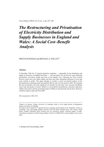
Sine Wave and Phasor ConceptsSine Wave and Phasor ConceptsSine waves are useful for illustrating thequality of the alternating current andvoltage wave forms, including theeffects of harmonic distortion.Much of this course will involve thevisual representation of electricitywithin metering circuits.Phasors (vectors) are useful indetermining how an electricity meter willrespond in calculating electrical powerand energy.This portion of the session is intendedto ensure a common understanding ofthe methods used.Sine Wave and Phasor ConceptsSine Wave and Phasor ConceptsVoltage VoltsVoltageCurrent0 Volts- Volts360 degrees 1 CycleTime 1/60 secondVoltage and Current "in phase"shown as true (pure) sine waves(60 hertz system)Sine Wave and Phasor ConceptsCurrent as a true sine waveSine Wave and Phasor ConceptsVoltageVoltageCurrentCurrentCurrent shown with distortionThe load may cause distortion in both the current and voltage wave forms.Distortion may cause excessive conductor heating, voltage drops, and line lossesVoltage and Current are in phase15
Sine Wave and Phasor ConceptsSine Wave and Phasor ConceptsVoltageVoltageCurrentCurrent60 degree lag(inductive load)60 degree lagPhasor representationVoltageVoltage and Current are in phaseVoltage and Current are in phaseCurrent lags voltage by 60 degreesSine Wave and Phasor ConceptsCurrent lags voltage by 60 degreesSine Wave and Phasor ConceptsVoltageVoltageCurrentCurrent60 degree lag60 degree lagPhasor representationPhasor representationCurrentCurrentVoltageVoltageVoltage and Current are in phaseVoltage and Current are in phaseCurrent lags voltage by 60 degreesVoltageCurrent lags voltage by 60 degreesPhasors used inPower CalculationsSine Wave and Phasor ConceptsVoltageThe relationship between the phasors can be usedto determine:Current-60 degree lagCurrentPhase angle - in degrees lead or lagActive power - in Watts (W)Reactive power - in Reactive Volt-Amperes (VARs)Apparent power - in Volt-Amperes (VA)Power factor - as a ratio or percentPhasor representation60 degree lagThis can be demonstrated using the circuitfrom the previous exampleCurrentVoltageVoltage and Current are in phaseVoltageCurrent lags voltage by 60 degrees16
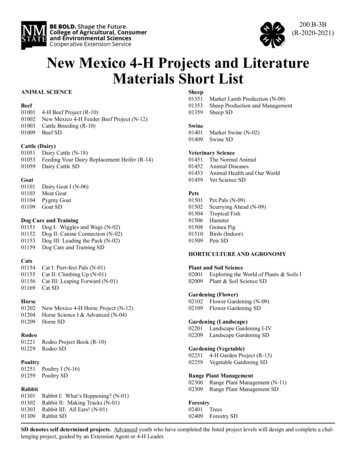
Phasors used inPower CalculationsPhasors used inPower CalculationsThe relationship between the phasors can be usedto calculate Watts:The relationship between the phasors can be usedto calculate Reactive Volt-amperes:Reactive VA (VARs)CurrentCurrentWatts (W)Watts (W)Active power (Watts) is comprised ofthe portion of the currentwhich is in phase with the voltage(the "in phase component")Reactive power (VARs) is comprisedof the portion of the current which is90 degrees out of phase with thevoltageVoltageWatts (W)Reactive VA (VARs)VoltagePhasors used inPower CalculationsPhasors used inPower CalculationsThe relationship between the phasors can be usedto calculate Volt-amperes:The relationship between the phasors can be usedto calculate values using the Power TriangleVolt-amperesVolt-amperes(VA)(VA)Reactive VA (Vars)Reactive VA (VARs)CurrentWatts (W)Watts (W)Volt-amperes(VA)Apparent power (VA) iscomprised of the total current,without regard to phase angle.The value of any quantity can bedetermined using:1) any other two values, or2) one other value and the phase angleVoltagePower MetersCurrent60 degree lagVoltageEnergy MetersWatt (W) meter:Watt hour (Wh) meter:Measures active electrical power,normally displayed as kW.Measures active electrical energy, integrating active powerwith respect to time, normally displayed as kWh.Reactive Volt-Ampere (VAR) meter:VAR hour (VARh) meter:Measures reactive electrical power,normally displayed as kVAR.Measures reactive electrical energy, integrating reactivepower with respect to time, normally displayed as kVARh.Volt-Ampere (VA) meterVA hour (VAh) meterMeasures apparent electrical power,normally displayed as kVA.Measures apparent electrical energy, integrating apparentpower with respect to time, normally displayed as kVAh.17
Electrical Power and EnergySine Wave and Phasor ConceptsPower - the rate of energy output or transferQuestions?Energy - capacity to do work- integration of power over timeComments?The methods for calculation of these values willbe covered in more detail later in the course.18
Electricity Metering Circuits1 Phase MeteringElectricity MeteringCircuitsVarious methods are used tosupply and measure1 Phase (Single Phase) electricityPrepared and presented by:George A. Smith, Measurement CanadaPaul G. Rivers, Measurement Canada2006Electricity Metering CircuitsElectricity Metering Circuits1 Phase Metering1 Phase 2-Wire1 Phase (single phase) supply methods:1 Phase 2-Wire supply,1 Phase 3-Wire supply,Supply TransformerC1 Phase 2-Wire services are typicallysupplied from a 3 Phase supply transformer.A1 Phase (single phase) metering methods:1 Phase 1 Element meter1 Phase 1.5 Element meter,1 Phase 2 Element meterElectricity Metering CircuitsElectricity Metering Circuits1 Phase 2-Wire1 Phase 2-WireSupply TransformerSupply TransformerCConsumer LoadC240 volts240 voltsABThe 3 Phase supply transformer is shown asa 3 Phase 4-wire Wye configuration, usinga different color for each phase voltage.B240 voltsA1 Phase electricity is suppliedby one of the 3 phasesB19The consumer is supplied1 Phase electricity at one voltage
Electricity Metering CircuitsElectricity Metering CircuitsBlondel's Theorum1 Phase 2-WireSupply Transformer240 volts240 voltsA240 voltsABlondel's Theorum states: In a system of N conductors,N-1 metering elements, properly connected,will measure the power or energy taken.The connection must be such that all voltage coils have a common tieto the conductor in which there is no current coil.BBlondel's Theorem requires (N wires - 1) elements1 Element 1 Current Sensor 1 Voltage SensorElectricity Metering CircuitsElectricity Metering Circuits1 Phase 2-Wire1 Phase 2-WireSupply Transformer1 Element MeterSupply TransformerConsumer LoadC1 Element MeterConsumer LoadC240 volts240 volts240 voltsAB240 voltsAB1 Element: 1 Current Sensor1 Voltage Sensor Current Sensor1 Element: 1 Current Sensor1 Voltage Sensor Current Sensor Voltage SensorElectricity Metering CircuitsElectricity Metering Circuits1 Phase 2-Wire1 Phase 3-WireSupply Transformer1 Element MeterConsumer Load1 Phase 3-Wire servicesare the common method ofsupplying electricity tohomes in North AmericaC240 volts240 voltsABConsumer LoadC240 voltsBMeterSupply TransformerConsumer LoadC1 Element Meter satifies Blondel's Theorem,and provides accurate measurement Current Sensor Voltage Sensor20
Electricity Metering CircuitsElectricity Metering Circuits1 Phase 3-Wire1 Phase 3-WireSupply Transformer(s)Supply Transformer1 Phase 3-Wire services are typicallysupplied from a 3 Phase supplyCThe transformer secondary circuits areisolated from the primary circuitsCPrimaySecondaryAABBElectricity Metering CircuitsElectricity Metering Circuits1 Phase 3-Wire1 Phase 3-WireSupply TransformerSupply TransformerCCConsumer Load120 volts240 volts240 volts240 volts120 voltsAAThe secondary circuit supplieselectricity to the consumerBThe secondary transformer is givena center tap to groundBNeutralElectricity Metering CircuitsElectricity Metering Circuits1 Phase 3-Wire1 Phase 3-WireSupply TransformerCSupply TransformerConsumer Load120 voltsC120 volts240 voltsConsumer Load120 volts120 volts240 volts240 volts120 volts120 voltsA240 volts120 voltsABBNeutralThe consumer has a choice of120 volts or 240 voltsNeutral21The consumer has a choice of120 volts or 240 volts
Electricity Metering CircuitsElectricity Metering Circuits1 Phase 3-Wire1 Phase 3-WireSupply Transformer1 Phase 3-Wire serviceusing a Blondel Compliant2 Element meterCConsumer Load120 volts120 volts240 volts240 volts120 volts120 voltsABThe consumer has a choice of120 volts or 240 voltsNeutralElectricity Metering CircuitsElectricity Metering Circuits1 Phase 3-Wire1 Phase 3-WireSupply TransformerC2 Element MeterSupply TransformerConsumer LoadLine 1120 voltsC120 volts2 Element MeterConsumer LoadLine 1120 volts120 volts240 volts120 voltsLine 2240 volts120 volts120 voltsAANeutralBNeutralBMeasurement using a 2 Element meterNeutral120 voltsLine 2A current sensor is added to Line 1Neutral Current SensorElectricity Metering CircuitsElectricity Metering Circuits1 Phase 3-Wire1 Phase 3-WireSupply TransformerC2 Element MeterSupply TransformerConsumer LoadLine 1120 voltsC120 volts2 Element MeterConsumer LoadLine 1120 volts120 volts240 volts120 voltsLine 2240 volts120 volts120 voltsANeutral120 voltsANeutralBLine 2NeutralBA current sensor is added to Line 2Neutral Current SensorA voltage sensor is connected betweenLine 1 and neutral (ground) Current Sensor22 Voltage Sensor
Electricity Metering CircuitsElectricity Metering Circuits1 Phase 3-Wire1 Phase 3-WireSupply TransformerC2 Element MeterSupply TransformerConsumer LoadLine 1120 voltsC120 volts2 Element MeterConsumer LoadLine 1120 volts120 volts240 volts120 volts240 volts120 volts120 voltsLine 2AANeutralB Current Sensor2 Elements: 2 Current Sensors2 Voltage SensorsNeutral Voltage Sensor Current Sensor Voltage SensorElectricity Metering CircuitsElectricity Metering Circuits1 Phase 3-Wire1 Phase 3-WireSupply TransformerCNeutralBA voltage sensor is connected betweenLine 2 and neutral (ground)Neutral120 voltsLine 22 Element MeterConsumer Load120 volts1 Phase 3-Wire serviceusing a Non Blondel Compliant1.5 Element meter120 volts240 volts120 volts120 voltsAB2 Element Meter satifies Blondel's Theorem, providingmeasurement accuracy in all loading conditions.Neutral Current SensorElectricity Metering CircuitsElectricity Metering Circuits1 Phase 3-Wire1 Phase 3-WireSupply TransformerC Voltage Sensor1.5 Element MeterSupply TransformerConsumer LoadLine 1120 voltsC120 volts1.5 Element Meter120 voltsConsumer Load120 volts240 volts120 voltsLine 2240 volts120 volts120 voltsAANeutralBNeutral120 voltsBThe 1.5 element meter still has a currentsensor connected to Line 1 and Line 2Neutral Current SensorHowever only one voltage sensor is used Current Sensor23 Voltage Sensor
Electricity Metering CircuitsElectricity Metering Circuits1 Phase 3-Wire1 Phase 3-WireSupply TransformerC1.5 Element MeterSupply TransformerConsumer LoadLine 1120 voltsC120 volts120 volts1.5 Element MeterConsumer Load120 volts240 volts120 voltsLine 2240 volts120 volts120 voltsAANeutralBBThe voltage sensor is connected between the240 volt supply lines, Line 1 and Line 2Neutral120 volts Current SensorNeutral Voltage SensorElectricity Metering Circuits1.5 Elements does not satisfyBlondel's Theorem (N-1 elements),however it will measure accuratelyunder balanced voltage conditions.Electricity Metering Circuits1 Phase 3-WireTransformer Type InstallationSupply TransformerC1 Element Meter120 voltsConsumer Load120 volts240 volts120 volts120 voltsABNeutralThe 1 element meter functions similar to a 1.5 elementmeter, and does not satisfy Blondel's Theorem, but willmeasure accurately under balanced voltage conditions. Ring Style Current Transformer Voltage SensorElectricity Metering CircuitsElectricity Metering Circuits24
Electricity Metering CircuitsElectricity Metering Circuits1 Phase MeteringQuestions?Comments?Next: 3 Phase 4-Wire Open DeltaElectricity Metering CircuitsElectricity Metering Circuits3 Phase 4-Wire Open Delta3 Phase 4-Wire Open DeltaSupply TransformerCThe 3 Phase 4-Wire open delta serviceis an economical way of providing acombination of a single phase 3-wireservice and a limited supply of polyphasepower.MeterConsumer LoadCLine 1120 volts120 volts120 voltsLine 2A120 volts120 volts120 voltsBNeutralThe service configuration begins as asingle phase 3-wire service.Electricity Metering CircuitsElectricity Metering Circuits3 Phase 4-Wire Open DeltaSupply TransformerCMeterSupply TransformerCConsumer LoadCLine 1120 volts3 Phase 4-Wire Open Delta120 volts120 volts120 voltsALine 2120 voltsMeter120 volts120 volts120 voltsA120 voltsBConsumer LoadCLine 1Line 2120 volts120 volts120 voltsB240 volts240 voltsNeutral240 volts208 voltsNeutralThe non-polarity connection of the 'A' phasesecondary winding is connected to the polarityconnection of the 'C' phase secondary winding.240 volts25208 volts'A' phase power is supplied to the consumer
Electricity Metering CircuitsElectricity Metering Circuits3 Phase 4-Wire Open Delta3 Phase 4-Wire Open Delta240 voltsSupply TransformerCMeterLine 1120 volts240 voltdelta120 volts120 voltsLine 2120 voltsA240 voltsSupply TransformerCConsumer LoadCA120 volts120 voltsBLine 2120 voltsABB208 volts240 voltsNeutral240 volts240 voltdelta120 volts120 voltsB240 voltsConsumer LoadCALine 1120 volts120 volts120 volts3 Element Meter208 voltsNeutralThe consumer is provided with a 240 volt 3phase open delta power supply240 volts208 voltsA current sensor and voltagesensor are added Current SensorElectricity Metering Circuits Voltage SensorElectricity Metering Circuits3 Phase 4-Wire Open Delta3 Phase 4-Wire Open Delta240 voltsSupply TransformerC3 Element MeterConsumer LoadCALine 1120 volts120 volts120 voltsLine 2120 voltsAB120 voltsBQuestions?240 voltdelta120 voltsComments?208 volts240 voltsNeutral240 volts208 voltsThe A phase voltage sensorreceives 208 volts Current SensorNext: Polyphase Supply & Metering Methods Voltage SensorElectricity Metering CircuitsElectricity Metering CircuitsPolyphase MeteringPolyphase supply methods3 Phase 4-Wire Wye,3 Phase 3-Wire Wye (grounded)2 Phase 3-Wire Wye (network)Various methods are used tosupply and measurepolyphase electricityPolyphase metering methods:2 Element meter,2.5 Element meter,3 Element meter26
Electricity Metering CircuitsElectricity Metering Circuits3 Phase 4-Wire Wye Service3 Phase 4-Wire Wye Servicehas a grounded neutral conductor3 Phase 4-Wire servicesare a common method ofsupplying polyphase electricityto commercial andindustrial consumersConsumer LoadSupply TransformerCABNeutral3 Phase 4-Wire Wye supplyElectricity Metering CircuitsElectricity Metering Circuits3 Phase 4-Wire Wye Service3 Phase 4-Wire Wye ServiceConsumer LoadSupply TransformerConsumer LoadSupply TransformerCCAABBNeutralNeutralA 1 phase load is appliedA 2 phase load is appliedElectricity Metering CircuitsElectricity Metering Circuits3 Phase 4-Wire Wye Service3 Phase 4-Wire Wye ServiceConsumer LoadSupply TransformerSupply TransformerCConsumer LoadCAABBNeutralNeutralA 3 phase load is appliedBlondel's Theorem requires N-1 elements27
Electricity Metering CircuitsElectricity Metering Circuits3 Phase 4-Wire Wye Service3 Phase 4-Wire Wye ServiceSupply TransformerMeterConsumer LoadMeterSupply TransformerCConsumer LoadCAABABNeutralNeutralA 3 element meter is recommended Current SensorElectricity Metering CircuitsElectricity Metering Circuits3 Phase 4-Wire Wye Service3 Phase 4-Wire Wye ServiceSupply TransformerMeterConsumer LoadMeterSupply TransformerCConsumer LoadCAAABABBNeutralNeutral Current Sensor Voltage Sensor Current Sensor Voltage SensorElectricity Metering CircuitsElectricity Metering Circuits3 Phase 4-Wire Wye Service3 Phase 4-Wire Wye ServiceSupply TransformerMeterConsumer LoadSupply TransformerCMeterConsumer LoadCCAAABBABBNeutralNeutral Current Sensor Voltage Sensor Current Sensor28 Voltage Sensor
Electricity Metering CircuitsColour coding of the supply wires to a transformertype meter will reduce the probability of wiringerrors. In Canada, the color code is as follows:3 Phase 4-Wire Wye ServiceSupply Transformer3 Element MeterRed --------------------------- A phase voltageYellow ----------------------- B phase voltageBlue -------------------------- C phase voltageWhite ------------------------ NeutralGreen ------------------------ GroundRed with White tracer - A phase current, polarityRed with Black tracer - A phase current, returnYellow with White tracer - B phase current, polarityYellow with Black tracer - B phase current, returnBlue with White tracer - C phase current, polarityBlue with Black tracer - C phase current, returnConsumer LoadCCAABBNeutral Current Sensor Voltage SensorElectricity Metering Circuits3 Element Wye Meter InstallationCurrent Tranformers3 Element Meter InstallationElectricity Metering Circuits3 Phase 4-Wire Wye ServiceQuestions?Comments?Next: 3 Phase 4-Wire Wye, 2.5 element meter29
Electricity Metering CircuitsElectricity Metering Circuits3 Phase Metering3 Phase 4-Wire Wye Service2.5 element meter2.5 Element Meter3 Phase 4-Wire Wye serviceis sometimes fitted with a2.5 element meterSupply TransformerCConsumer LoadCAABBNeutralA phase and C phase are complete elementsElectricity Metering CircuitsElectricity Metering Circuits3 Phase 4-Wire Wye Service3 Phase 4-Wire Wye Service2.5 element meter2.5 element meter2.5 Element MeterSupply TransformerC2.5 Element MeterConsumer LoadSupply TransformerCCConsumer LoadCAAAABBBBNeutralNeutralB phase voltage is not measured (1/2 element)If the voltage is not balanced, errors will occurThe 2.5 element meter is not recommendedElectricity Metering CircuitsElectricity Metering Circuits3 Phase 3-Wire Grounded Wye3 Phase 3-Wire Grounded Wyemay be used for high voltage transmission lines3 Phase 3-Wire grounded Wyemay be used for high voltagetransmission linesSupply TransformerConsumer LoadCAB3 Phase 3-Wire Wye supply (grounded)30
Electricity Metering CircuitsElectricity Metering Circuits3 Phase 3-Wire Grounded Wye3 Phase 3-Wire Grounded WyeSupply Transformer3 Element MeterConsumer LoadCSupply TransformerC2 Element MeterConsumer LoadCCAAABBABBNeutral2 element metering is accurate if there is no ground currentElectricity Metering CircuitsElectricity Metering Circuits3 Phase 3-Wire Network Service3 Phase 3-Wire Network Service120 / 208 volt load3 Phase 3-Wire Network servicesare a common method of providingboth 120 and 208 volt electricityto apartment complexesConsumer LoadSupply TransformerCA208 voltsB120 voltsNeutralElectricity Metering CircuitsElectricity Metering Circuits3 Phase 3-Wire Network Service3 Phase 3-Wire Network Service120 / 208 volt load120 / 208 volt loadConsumer LoadSupply TransformerAConsumer LoadSupply Transformer2 Element Meteris requiredC2 Element MeterCA208 voltsA208 voltsBB120 volts120 voltsNeutralNeutral Current Sensor31 Voltage Sensor
Electricity Metering CircuitsElectricity Metering Circuits3 Phase 3-Wire Network Service120 / 208 volt loadConsumer LoadSupply Transformer2 Element MeterCAA208 voltsBB120 voltsNeutral Current Sensor120/208v Network metersin an apartment complex Voltage SensorElectricity Metering CircuitsElectricity Metering Circuits3 Phase 3-Wire Delta Service3 Phase 3-Wire Delta Service3 Phase 3-Wire Delta servicesare a common method of providing3 phase electricity to large motorloads such as pumping stationsDelta connectedSupply TransformerA3 Phase 3-Wire Delta ServiceDelta connectedConsumer LoadDelta connectedSupply TransformerCDelta connectedConsumer Load2 Element MeterCCABBElectricity Metering Circuits3 Phase 3-Wire Delta ServiceCABElectricity Metering CircuitsDelta connectedSupply TransformerConsumer LoadCCAABB32AB
Electricity Metering CircuitsElectricity Metering Circuits3 Phase 3-Wire Delta ServiceDelta connectedSupply Transformer3 Phase 3-Wire Delta ServiceDelta connectedConsumer Load2 Element MeterCDelta connectedSupply TransformerCDelta connectedConsumer Load2 Element MeterCCAAABBABB Current Sensor Current SensorElectricity Metering Circuits Voltage SensorElectricity Metering Circuits3 Phase 3-Wire Delta ServiceDelta connectedSupply TransformerDelta connectedConsumer Load2 Element MeterCQuestions?CAABB Current SensorComments? Voltage Sensor33
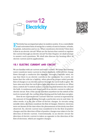
Single Phase Load AnalysisSingle Phase and Polyphase- Single Phase 2-Wire LoadLoad Analysis- Single Phase 2-Wire Service1.0 Element Meter- Single Phase 3-Wire Service2 Element Meter1.5 Element MeterPrepared and presented by:George A. Smith, Measurement CanadaPaul G. Rivers, Measurement Canada2006Single Phase 2-Wire LoadSingle Phase 2-Wire LoadWatt MeterSupply TransformerConsumer LoadCAConsumer LoadC10 AMPSV120 voltsWatt MeterSupply TransformerAA10 AMPSV120 voltsABBMotorMotorThe motor contains many turns in the internal coil windings.The current is therefore inductive as well as resistive andwill cause a magnetic field to be present.The above drawing shows a simple single phase motor circuit,which contains a wattmeter, an ammeter and a voltmeter.As a result the current will lag the voltage. In this case, let'sassume the lag to be 30 degrees.The basic principles here apply equally to polyphase circuits.Single Phase 2-Wire LoadSupply TransformerSingle Phase 2-Wire LoadWatt MeterConsumer LoadCASupply Transformer10 AMPSV120 voltsWatt MeterConsumer LoadCA120 voltsA10 AMPSVABBMotorApparent Power is equal to the voltage times the currentand is expressed in volt-amperes (VA) or more commonly in KVAMotorApparent Power E x I 120volts x 10amps 1200 VAThis is the power which the utility delivers to the customer and ismeasured by the voltmeter and ammeter.I line 10 amps30 degreesE 120 voltsNote: E voltsI amperes34
Single Phase 2-Wire LoadSingle Phase 2-Wire LoadWatt MeterSupply TransformerConsumer LoadCAConsumer LoadCV120 voltsWatt MeterSupply Transformer10 AMPSAA10 AMPSV120 voltsABBMotorActive Power E x I x cosine 0* 120volts x 10amps x cos 30 degrees 1200 VA x .866 1039.2 wattsActive Power is equal to the voltage times the in phasecomponent of the current and is expressed in watts (W) or morecommonly in kW.This is the power which is used to drive the shaft in the electric motorand is the power which is of value to the customer and measuredby the wattmeterThe Phase angle or Power Factoraffects the magnitude ofActive Power MeasurementMotorI 10 amps30 degreesIw (.866)E 120 volts0* theta phase angle of the currentSingle Phase 2-Wire LoadSingle Phase 2-Wire LoadWatt MeterSupply TransformerConsumer LoadCA10 AMPSA10 AMPSV120 voltsABConsumer LoadCV120 voltsWatt MeterSupply TransformerABMotorReactive Power is equal to the voltage times the component of theline current which is displaced from the voltage by 90 degrees and isexpressed in volt amp reactance (vars) or more commonly in KVARs.MotorReactive Power E x I x sine 0* 120 volts x 10 amps x 0.5 600 VARsI 10 ampsIm 5ampsThis is the power which is required to create and maintain the magneticfield in the electric motor. Reactive Power represents the reactive lossescreated by the customers motor.The Phase angle or PowerFactor also affects the magnitudeof the Reactive Power0* Theta phase angle of the current30 degreesIw (.866)E 120 voltsSingle Phase 2-Wire LoadSingle Phase 2-Wire LoadApparent Power delivered 1200 VAPower Factor 30 degreesReactive Powerlosses 600VARsQuestions?Usable Active Power 1039.2 WattsComments?The power triangle for this circuit reveals theapparent power delivered, the active power used bythe consumer, and the reactive power losses.Next: Single Phase 2-Wire Service35
Single Phase Load AnalysisSingle Phase 2-Wire ServiceSingle Phase 2-Wire Service1 Element MeterSupply TransformerCConsumer Load10 amps110 volts1 Element MeterABWhat is the apparent power delivered to thisconsumers 1 phase 2 wire service?Service is 110 volts, Load is drawing 10amps, unity power factorSingle Phase 2-Wire Service1 Element MeterSupply TransformerCSingle Phase 2-Wire ServiceC10 amps110 voltsConsumer Load10 amps110 voltsAABBApparent Power E x IApparent Power 110volts x 10ampsApparent Power 1100 vaWhat is the active power measured in this 1 phase2 wire service, by the 1 element meter?Service is 110 volts, Load is drawing 10amps, unity power factorSingle Phase 2-Wire ServiceSupply Transformer1 Element MeterCSingle Phase 2-Wire Service1 Element MeterSupply TransformerConsumer LoadC10 amps110 voltsConsumer Load10 amps1100 watts110 voltsAB1 Element MeterSupply TransformerConsumer LoadAActive Power E x I x cosine 0*Active Power 110 volts x 10 amps x 1.0Active Power 1100 wattsBIf this load of 1100 watts was on for 1.5 hrs,the meter would register the following energy.Energy Active Power x Time 1100watts x 1.5hrs 1650 watthours0* theta phase angle of the current36
Single Phase 2-Wire ServiceSingle Phase Load AnalysisSingle Phase 3-Wire ServiceQuestions?2 Element MeterComments?Next: Single Phase 3-Wire Service, 2 Element MeterSingle Phase 3-Wire Service, 2 Element MeterSupply TransformerCSingle Phase 3-Wire Service, 2 Element MeterSupply TransformerConsumer LoadLine 1C10 amps110 volts110 volts220 volts10 amps20 ampsLine 2110 volts5 ampsConsumer LoadLine 1110 voltsA220 volts20 ampsLine 25 ampsANeutralBNeutralBNeutralNeutralHow much active power is the consumers load drawing?Active Power Load 1 Load 2 Load 3 (E x I x cos0*) (E x I x cos0*) (E x I x cos0*)Note : Unity power factorE Voltage, I Current, PF 1.0, 0* theta phase angle of the currentSingle Phase 3-Wire Service, 2 Element MeterSupply TransformerCSingle Phase 3-Wire Service, 2 Element MeterSupply TransformerConsumer LoadC10 amps110 volts220 volts110 volts5 ampsA25 amps20 amps5 ampsANeutralBConsumer Load10 amps110 volts20 ampsLine 22 Elemen
Electricity Meters Metrology, is defined as the "Science of Measurement" Legal Metrology is intended to ensure the appropriate quality and credibility of measurements, which can result in significant benefits to society. Electricity Meters Electricity Meters The measurement of electricity