Transcription
BEE HIVE TEMPERATURE ANDSOUND MONITORA design project report presented to the Engineering division of theGraduate school of Cornell University in partial fulfillment of therequirements for the degree of Master of Engineering (ECE)ByMadhuri Kandepi (mk2335)Project Advisor: Dr. Bruce LandDegree Date: May 2015
AbstractMaster of Electrical Engineering ProgramCornell UniversityDesign Project ReportProject title: Bee Hive Temperature and Sound MonitorAuthor: Madhuri KandepiAbstract:The goal of the project is to provide a solution for remote monitoring of a beehive tomonitor the temperature and acoustics. A transmitter module is installed at the beehivewhich measures the temperature and audio levels (using temperature sensor andmicrophone) and transmits the information through a radio. A receiver module isinstalled inside the house (or any target location) which receives the input and displaysthe same on a graphic LCD. The communication between the transmitter and the receiverhappen using XBEE Pro modules (Radio communication). The hive data collection unitis solar powered and weather-proof.Beehive Temperature and Sound MonitorPage 2
Executive summaryThe project involves the design and implementation of a telemetry system to monitor thetemperature and sound intensity in a Beehive. The primary requirements for the systemare that the hive data collection unit should be solar powered, weather-proof, havetemperature probes and microphones compatible with hive conditions, cost to be less than 500, and ease of use.The system design consists of a temperature sensor to detect the temperature in a hive, amicrophone and necessary circuitry to measure the sound inside the beehive, twoMicrocontroller units each at the source (Beehive) and destination (Beehive owner’shouse), two XBEE Pro radios for the wireless data transfer between the source anddestination, a graphic LCD to display the data received from the hive, a solar panel anda 12V 7AH battery to make the hive data collection unit solar-powered.In order to achieve the objective of the project, necessary hardware and softwarecomponents are designed. To measure the temperature in the hive, a temperaturesensor, which is calibrated directly in º F, is used. An electret microphone and an opamp are used to measure the sound. Each microcontroller unit handles its owndedicated task. The microcontroller unit at the source handles data acquisition andtransmission of the acquired data through a RF radio. The microcontroller unit at thedestination handles data reception and display of the data. A graphic LCD is used todisplay the data. Log of the beehive data is also displayed on the LCD, in order tofacilitate the user to know and compare the data at different time instants i.e., tofacilitate the user to know about both the absolute as well as relative data.The planning and implementation of the project has gone well and smoothly. Workwas equally split between the two semesters. The system designed was able to achievesatisfactory results. The final deliverable is fairly compact and solid. The cost of theproject is also well within the limits.Beehive Temperature and Sound MonitorPage 3
Contents1.Introduction . 62.Design problem & System Requirements . 72.1Design Problem . 72.2System-level Requirements. 72.2.1Bee Hive Temperature and Sound Monitoring System (BHTSM) . 72.2.2Beehive Transmitter . 72.2.3Beehive Receiver . 83 RANGE OF SOLUTIONS. 93.1Microcontroller . 93.2Temperature Sensor . 93.3Sound Sensor . 93.4XBEE Pro Radio . 103.5Graphic LCD . 103.6Solar Panel . 103.7Battery . 104 DESIGN . 114.1Approach . 114.2Hardware . 114.2.1Beehive Transmitter . 114.2.1.1 Transmitter MCU (ATmega 1284P) . 124.2.1.2Temperature Sensor (LM34DZ) . 124.2.1.3Acoustics Measuring Circuitry . 134.1.1.1XBEE Pro Radio & Adaptor . 144.2.2Beehive Receiver . 144.2.2.1 Receiver MCU (ATMega 1284P) . 154.2.2.2XBEE Pro Radio . 154.2.2.3Graphic LCD . 154.3SOFTWARE . 164.3.1Beehive Transmitter . 164.3.1.1 ADC Sampling . 164.3.1.2 The Algorithm: . 174.3.2Beehive Receiver . 184.3.2.1 The Algorithm: . 195 TEST METHODOLOGY & DIFFICULTIES. 20Some of the key components (build and test) . 20Below are some of the difficulties/challenges faced during the course of the project. 226RESULTS AND OBSERVATIONS . 236.1Cost: bill of materials . 24Beehive Temperature and Sound MonitorPage 4
6.2Requirements Match . 237 CONCLUSION . 277.1 Summary . 277.2 Future Work . 277.3 More Compliance Considerations . 277.4 Ethical Considerations . 277.5 Legal Considerations. 278ACKNOWLEDGEMENTS . 289REFERENCES . 29APPENDICES . 30Appendix A: Installation and User Manual . 30Appendix B:XBEE Pro Radio. 31Appendix C: X-CTU Software . 32Appendix D: Schematics. 33Appendix E: Layouts . 34Beehive Temperature and Sound MonitorPage 5
1.IntroductionBeekeeping is a production branch of the agriculture. Honeybees are very importanteconomical insects not only for pollination of crops, but also for their valuable products.These products are used either directly as human food (honey) or as a raw material for animpressive number of medicinal, cosmetic, pastry produces, etc.In apiculture, one of the major problems is to monitor honeybee colonies for their health,population, and other biological activities. Beside honeybee diseases, one of the mostcommon problems in apiculture is colony losses because of unusual alteration inenvironmental conditions such as temperature, humidity etc.In the previous 20th century, when information technologies were not widely available,measurements of the bee colony temperature were done manually using thermocouplesand later special temperature loggers or iButtons. With the rapid development of IT, ithas become possible to develop whole sensor networks for temperature measurements.This project aims to monitor the hive conditions; temperature and sound and gives theopportunity for beekeepers to monitor their own bee colonies in real time at a low cost.With the help of a display device which will be installed in their house, the bee keeperscould know what is going on in the bee-hive from the comfort of their home.One of the main goals of this project is simplicity. The system should be reliable, easy tounderstand, easy to use, low cost, solar powered, and the results should be accurate. Thesystem designed meets all of these requirements.A user manual is provided in Appendix to show how to get a graphical interpretation ofcollected data.Beehive Temperature and Sound MonitorPage 6
2.Design problem & System Requirements2.1 Design ProblemThe goal of this project is to design a low cost, compact and reliable temperature and soundmonitor for monitoring the hive conditions. The hive data collection unit should be solarpowered and placed in weather proof boxes. A simple graphical display should be available todisplay the collected data at the destination. The system is composed of two sub-systems andthey are transmitter and receiver. Transmitter is responsible in collecting data (temperature andsound) from the beehive, arranging data into packet, and sending the packet to the receiver.Receiver is responsible in receiving packet and displaying the data on the graphical LCD.Finally, data is analyzed in some graphs.2.2 System-level Requirements2.2.1 Bee Hive Temperature and Sound Monitoring System (BHTSM)This section lists the requirements to be met by the Beehive temperature and sound monitoringsystem (BHTSM).[SYS-01] The BHTSM system shall include Transmitter module to relay temperature and soundNote: The requirements for the Beehive Transmitter are listed in Section 2.2[SYS-02] The BHTSM system shall include receiver module that receives and displays hivetemperature and acoustics.Note: The requirements for the receiver module are listed in Section 2.3[SYS-03] The BHTSM system shall read the beehive temperature.[SYS-04] The BHTSM system shall read the beehive acoustics details.[SYS-05] The BHTSM system shall wirelessly transmit information from hive to the destination.[SYS-06] The BHTSM system shall indicate if the data is out of range.[SYS-07] The bill-of-materials for the BHTSM system shall not exceed 500.[SYS-08] The BHTSM system shall be designed to be weather-proof (outdoor beehive).[SYS-09] The BHTSM system shall be designed considering power saving options.[SYS-10] The BHTSM system shall work with a range of 1500 meters.[SYS-11] The BHTSM system shall read temperatures in F (Degrees Fahrenheit).[SYS-12] The BHTSM system shall measure temp with ( /-)1 degree accuracy.[SYS-13] The BHTSM system shall read accurate sound intensity levels in the hive.2.2.2 Beehive TransmitterThis section lists the requirements to be met by the Beehive Transmitter (BHT).[BHT-01] The BHT shall read temperature and sound inside the beehive in periodic intervals.[BHT-02] The BHT shall consume less power.Beehive Temperature and Sound MonitorPage 7
[BHT-03] The BHT shall wirelessly transmit temperature details.[BHT-04] The BHT shall wirelessly transmit acoustics details.[BHT-05] The BHT shall be solar powered.2.2.3 Beehive ReceiverThis section lists the requirements to be met by the Beehive Receiver (BHR).[BHR-01] The Beehive Receiver (BHR) shall receive wireless/radio inputs.[BHR -02] The BHR shall understand and parse the received beehive temperature information[BHR -03] The BHR shall understand and parse the received beehive acoustics information[BHR -04] The BHR shall display the received temperature in F.[BHR -05] The BHR shall graphically display the hourly temperature history.[BHR -06] The BHR shall display the received sound intensity information in dB (Decibels).[BHR -07] The BHR shall graphically display the hourly sound level history.Beehive Temperature and Sound MonitorPage 8
3RANGE OF SOLUTIONSThe core requirement can be achieved by using multiple options including wired and Wi-Fibased communication. But the following solution had been chosen for its simplicity, reliabilityand cost effectiveness.The chosen solution at a high level includes two major components, Beehive transmitter andReceiver. Transmitter is responsible for reading hive conditions and transmitting necessary data.Receiver is responsible for receiving the transmitted data and display the analysis. XBee Proradios are responsible for the communication between these 2 components. Radiocommunication is easy to build, reliable and cost effective.The solution also uses various hardware components including microcontrollers, temperaturesensor, acoustics measurement circuitry, a solar panel, a 12V 7 AH battery, a graphical LCD todisplay the information and a bunch of other components like resistors and capacitors.This section these majors components of the system are introduced.3.1 MicrocontrollerAtmel AVR microcontroller (ATmega 1284p) is chosen for this project because I am relativelyfamiliar with it. It has been used in ECE4760-Microcontroller class which I had taken duringfall semester and general technical support is available from Dr. Land or various websites. It is agood fit for the project as it has 8 built-in ADC (Analog to Digital Conversion) channels, Builtin USART, Interrupts & Timers, Sufficient Program and Data memory, Various Sleep Modes,Suitable frequency etc. and is low in cost.3.2 Temperature SensorFor measuring the temperature, LM34DZ sensor was used because it is calibrated directly indegrees Fahrenheit, linear 10.0 mV/ F scale factor, suitable for remote applications, Low costdue to wafer-level trimming, operates from 5 to 30 volts, low self-heating, 0.18 F in still air etc.3.3 Sound SensorFor measuring the sound inside the beehive an electret microphone and LM358 op-amp are usedalong with a bunch of other resistors and capacitors. The circuitry is explained in detail in thehardware section of the report.Beehive Temperature and Sound MonitorPage 9
3.4 XBEE Pro RadioFor the communication between Transmitter and Receiver, XBE Pro Radios are used. This isbecause it has the radios have an outdoor/RF Line-of-Sight Range Int’l 5000 ft (1500 m), serialData Rate 1200 bps - 1 Mbps, fast 250 kbps RF data rate to the end node, 2.4 GHz forworldwide deployment, sleep modes supported for extended battery life.3.5 Graphic LCDFor displaying the data at the receiver end, graphical LCD KS0108 (128X64) is used. This isbecause, it allows full graphical control compared to a regular 16x2 LCD. Also, it suits theproject requirement of showing the data graphically at the receiver. It is the most commonlyused graphical LCD and has good online support for header files and user manuals on how touse it. It also has a low power white LED back-light to help the user view the screen clearly.3.6 Solar PanelThe Solar panel used in the project is a 2 Watt, 12V battery maintainer panel. As the batterybeing used in the project is a 12V battery, it serves the purpose. It can easily be connected anddisconnected to the battery. No direct sunlight is needed and the panel works even in cloudyconditions. It is overcharge and discharge protected. Also, it is lightweight and compact indesign. It provides a voltage between 16 and 23 Volts DC in full sun.3.7 BatteryThe battery used in the project is a 12V 7AH battery. It is sealed and maintenance-free. Thebattery has a long service life; under normal operating conditions it works five to six years instandby applications or between 200 and 1000 charge/discharge cycles depending upon depth ofdischarge. It is resistant to shock, vibration, chemicals, and heat. It is compact. It operates over atemperature range of -76 F to 140 F. All these features make it very suitable for the project.Beehive Temperature and Sound MonitorPage 10
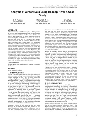
4DESIGN4.1 ApproachThe project is divided into two parts: The Transmitter Circuit and The Receiver Circuit.The data flow of the project is linear. First, the temperature and sound intensity information isread from the sensors. The data is then fed to two separate ADC (Analog to Digital Converter)channels in the transmitter MCU which samples the signals at 8KHz and converts them intodigital signals. Then, the digital data is converted back to meaningful information and istransmitted to the Transmitter XBEE Pro Radio through USART. The Transmitter radiotransmits the information to the Receiver XBEE Pro Radio in the form of packets using wirelesscommunication. The Receiver radio receives the packets and then sends this information to theReceiver MCU using USART. The Receiver MCU analyses the data and displays it on thegraphical LCD interfaced to it.The flow is shown in the below block diagram.Figure 1 Block Diagram4.2 HardwareThe hardware is split into two main parts: The Transmitter Circuit and the Receiver Circuit.Both these circuits are explained in detail in this section.4.2.1Beehive TransmitterBeehive transmitter circuit is responsible for reading and transmitting hive conditions. Itsschematic diagram is below.Beehive Temperature and Sound MonitorPage 11
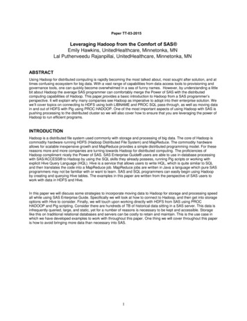
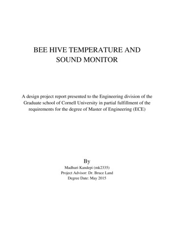
Fig 2: Schematic Diagram for Beehive Transmitter CircuitThe Transmitter circuit mainly consists of Transmitter MCU, Temperature sensor, Acousticsmeasuring circuitry, Transmitter radio.Once built and tested, I built a PCB for the transmitter using EAGLE software. Then I orderedthe printing of PCB online at Advanced Circuits (4pcb.com) by uploading necessary gerberfiles. Refer to “Appendix E” for detailed information on PCB Transmitter board details.4.2.1.1 Transmitter MCU (ATmega 1284P)The transmitter MCU is responsible for reading the information from the sensors, operating onthe information read, transform the same to user understandable information and transmitting itthrough USART to Transmitter XBEE radio. This MCU has a temperature sensor, electretmicrophone, operational amplifier, and a XBEE Radio (Transmitter Radio) interfaced to it. TheMCU uses specific algorithm to transmit the information. This is explained in detail in thesoftware section below.4.2.1.2 Temperature Sensor (LM34DZ)The temperature sensor should be capable of measuring a wide range of temperatures. In theproject, LM34DZ is used to measure the temperature in the beehive. It is calibrated directly in F and measures from -50 to 300 F.Below is the diagram of LM34DZ. It has 3 pins: Ground, Power supply and Vout. The Vout pinis connected to ADC channel 7. The temperature sensor reads the temperature and passes it onto the MCU (A7). MCU translates the value to corresponding Fahrenheit value and transmits thesame.Beehive Temperature and Sound MonitorPage 12
Figure 2 LM34DZBeehive Temperature RequirementAs honey bees are social insects, a honeybee colony can survive when the temperature of theexternal environment is between -4 and 118 ºF. However, they show the best performance atthe temperatures between 70 and 95ºF. When the temperature falls below 57ºF, thehoneybee starts not leaving the hive and forming a ball (winter cluster). When the temperaturefalls below 43 ºF, the hive has the appearance of an exact ball. It is known that each bee canproduce a heat of 0.1 calorie per minute at 50ºF. Also, depending on various activities going oninside a beehive, the temperature varies widely. For example, when the temperature drops to 57 F, the bees begin to form a tight cluster. Within this cluster the brood (consisting of eggs, larvae,and pupae) is kept warm-about 93 F – with heat generated by the bees. However, most of thetimes, the beehive temperature will be in the range of 60 F to 100 F.4.2.1.3 Acoustics Measuring CircuitryIn a beehive, the typical frequency range of the sound will be between 180Hz and 260Hz. So,the acoustic measuring circuitry i.e., the sound sensor built should be able to operate in thisband of frequency. The circuitry is shown in the Schematic diagram above.The audio amplifier circuit accepts a microphone audio input signal. The signal is fed intoLM358 op-amp. A 2nd order low-pass filter with a cutoff frequency at 500Hz and a high passfilter with a cutoff frequency at 50Hz are built using the op-amp. The filtered signal is then fedto the ADC through a 330Ω resistor.Since the ADC cannot read negative voltages, a bias voltage of 2.5V is chosen so that it sitsbetween 0V and Vcc. To achieve this bias, the input from the microphone is DC-biased to 2.5Vwith two 100kΩ resistors and a 68nF capacitor. The resulting biased signal is then amplifiedthrough a non-inverting amplifier circuit with high-pass cutoff frequency at 50Hz. The highpass cutoff frequency was chosen such that the DC bias voltage would not be amplified by thenon-inverting amplifier. This is also the reason for choosing the specific value for the capacitorat the biasing stage, since the high-pass cutoff frequency of the level-shifter should match withthat of the amplifier circuit.The mic-in circuit runs the input from the microphone through the biasing circuit. This signal isthen passed through a non-inverting amplifier with a 2MΩ resistor on the negative feedbackloop. This value was chosen after experimentally determining the maximum voltage swing ofBeehive Temperature and Sound MonitorPage 13
the mic-in signal to be around 20mV peak-to-peak. Thus, to be able to detect sounds ofreasonable strength and distance away from the microphone, the above resistor value is chosento obtain a gain of 133.33V/V, or 42.4 dB. This ensures that the maximum output of themicrophone results in a full voltage swing across the ADC range.Since the audio signal is sampled with the ADC at 8 KHz sampling rate, it must be low-passfiltered before the ADC conversion to remove aliasing. A 2nd-order Sallen-Key low-pass filteris built using the op-amp with a cutoff frequency of 500Hz.4.1.1.1 XBEE Pro Radio & AdaptorAn XBEE Pro radio is installed at the transmitter which is used for transmitting the temperatureand sound information read and transformed by the MCU. XBEE Pro has a UART interface andcan connect directly to a microcontroller. Using UART, the radio can be used to communicatebetween microcontroller to microcontroller or between PC to microcontroller. XBee Pro radio isdesigned for 3.3V system. So, in order to interface the radio with ATmega 1284p MCU, anadaptor kit is used.XBEERxTx5VGndFig 4. XBEE Radio with adaptorMCUTxRx5VGndTable1: XBEE and MCU ConnectionsThe adaptor can be used to interface for 5V microcontroller board. The XBEE radio can beconnected to either a PC or MCU using this adaptor. The radio is mounted on top of the adaptorkit as shown in figure 8. This connection is used to configure the radio which is explained indetail in the software section. Once the radios are configured, then they are connected to theMCU using headers. The connections between the radio and the USART of the MCU are shownin the above table.Once the radios are configured and the hardware is set up as explained above, one can transmitand receive data using the radios. A XBEE Pro radio could be configured in differentconfiguration depending on the network topology. Various network topologies are explained indetail in the Appendix section of this report4.2.2Beehive ReceiverBeehive Temperature and Sound MonitorPage 14
Beehive receiver circuit is responsible for receiving the transmitted values from the transmitter usingXBEE, analyze the received values and display them on an LCD.The schematic diagram of the receiver circuit is shown below.Fig 5. Schematic Diagram of Beehive Receiver CircuitThe A0, C0 etc pins represent the port pins on the MCU.Once built and tested, I built a PCB for the receiver using EAGLE software. Refer to “AppendixE” for detailed information on PCB Receiver board details.4.2.2.1 Receiver MCU (ATMega 1284P)The Receiver MCU is responsible for the reception of the data and data display. This MCU hasan XBEE Radio (Receiver Radio) and a graphic LCD interfaced to it.4.2.2.2 XBEE Pro RadioAn XBEE Pro radio is installed at the Receiver which receives the temperature and soundinformation transmitted by the transmitter through XigBee protocol.4.2.2.3 Graphic LCDKS0105 graphic LCD is used for displaying the temperature and sound information. It has ablue background with 128 x 64 'monochrome' white pixels. For the contrast adjustment, a 10Kcontrast pot is used. The pin description and MCU connections are explained in detail in thetable below. The connections are shown in the picture below.Figure 3 Receiver MCU Connected to Graphic LCDPINSYMBOL FUNCTIONBeehive Temperature and Sound MonitorMCU PINPage 15
5GroundPower supply ( 5 V)Contrast adjustmentData/instructionData read/writeH L enable signalData bus lineData bus lineData bus lineData bus lineData bus lineData bus 920DB6DB7CS1CS2RSTVEEAKData bus lineData bus lineChip select for IC1Chip select for IC2ResetNegative voltage outputPower supply for LED ( 4.2 V), RA 0 ΩPower supply for LED (0 V)PC6PC7PA0PA1VCCVCCGNDTable 1 KS0108 Pin Description and MCU Connections4.2.3PCB boardsThe resulting circuits (both transmitter and receiver) are then4.3 SOFTWAREThe software portion is split into two independent project modules i.e. one for the TransmitterMCU and the other for the Receiver MCU.4.3.1Beehive TransmitterThe transmitter MCU is responsible for the data acquisition, converting the analog data signalinto digital signal by ADC sampling and transmitting the processed data to transmitter Radiothrough USART.4.3.1.1 ADC SamplingThe temperature data and modified audio signal from the audio analog circuit was fed into theADC port A.7 and A.3 respectively. The DC bias voltage was fed into A.1. The ADC voltagereference was set to AVCC. By default, the successive approximation circuitry requires an inputclock frequency between 50kHz and 200kHz to get maximum resolution (according to theAtmel Mega1284 specifications). The ADC is set to run at 125 kHz and it takes 13 ADC cyclesBeehive Temperature and Sound MonitorPage 16
to produce a new 10-bit ADC value (ranging from 0-1023), or about 104us. Since 10-bit ADCresult is used, the ADLAR in ADC was set to zero.4
2.2.1 Bee Hive Temperature and Sound Monitoring System (BHTSM) This section lists the requirements to be met by the Beehive temperature and sound monitoring system (BHTSM). [SYS-01] The BHTSM system shall include Transmitter module to relay temperature and sound Note: The requirements for the Beehive Transmitter are listed in Section 2.2