Transcription
HOTRUNNERTECHNOLOGYHot Runner System Installation GuideService and Maintenance / Nozzle 12EX16 / 16EX22 Series10.1.5 Nozzle 12EX16 / 16EX22 SeriesNOTICEAlways tighten the screws to the torque specified in the respective table in section 13.Hot Surfaces HazardContact between the skin and hot surfaces could result in burns.Use personal protective equipment, such as gloves, apron, sleeves and faceprotection, to guard against burns.When servicing or handling the hot runner system outside the manifold platesor the injection molding machine, care must be taken to heed the hot surfaceexposure warnings.For first aid contact your medical / safety representing.Hazard of Pressurized AirPressurized air blow can result in hot plastic or foreign bodies entering theeyes, causing vision damage.Following work must be carried out by qualified and experienced persons.Use personal protective equipment: Face protection, hearing protection andgloves.NOTICEHazard of Material DamageWithout consulting Synventive it is not permitted to do modifications to thehot runner system e.g. geometrical changes to the nozzle tip, except the partshape adjustment in the area of material allowance.Master Language is EnglishENHot Runner System Installation GuideRESTRICTED: Property of Synventive.- 323 For limited third party distribution based on need and intended use.SVC-17-0001 EN-Rev11All rights reserved. Errors and omissions excepted 2019 Synventive Molding Solutions
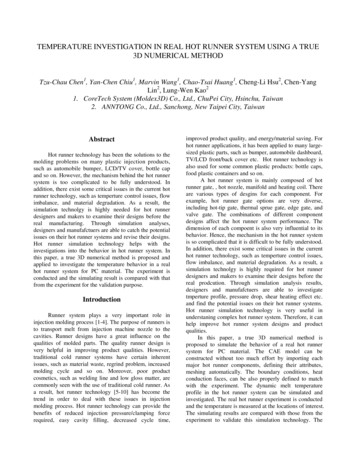
HOTRUNNERTECHNOLOGYHot Runner System Installation GuideService and Maintenance / Nozzle 12EX16 / 16EX22 SeriesTechnical Data - Threaded Nozzle 12EX16 / 16EX22 SeriesDoc006967.pngThreaded Nozzle 12EX16Flow bore (J)Ø 16 mm (Ø 18 mm)Nozzle length, flexible (L)200 – 650 mmNozzle cutout (D)Ø35 / Ø 50 mm (Ln 400 mm)Ø35 / Ø 50 / Ø 60 mm (Ln 400 mm)Ø35 / Ø 50 / Ø 60 mm / Ø 80 (Ln 650 mm)Doc006969.pngThermocoupleType J, Type KNozzle tipsVSP, VTP, VSW, VTW, TFP, TTP, TTWThreaded Nozzle 16EX22Flow bore (J)Ø 22 mm (Ø 20 mm / Ø 24 mm)Nozzle length (L)200 – 650 mmNozzle cutout (D)Ø43 / Ø 60 mm (Ln 450 mm)Ø43 / Ø 60 / Ø 70 mm (Ln 450 mm)Ø43 / Ø 60 / Ø 70 mm / Ø 95 (Ln 650 mm)Doc006970.pngMaster Language is EnglishThermocoupleType J, Type KNozzle tipsVSP, VTP, VSW, VTW, TFP, TTP, TTWENHot Runner System Installation GuideRESTRICTED: Property of Synventive.- 324 For limited third party distribution based on need and intended use.SVC-17-0001 EN-Rev11All rights reserved. Errors and omissions excepted 2019 Synventive Molding Solutions
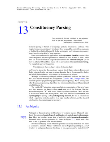
HOTRUNNERTECHNOLOGYHot Runner System Installation GuideService and Maintenance / Nozzle 12EX16 / 16EX22 SeriesParts of the Nozzles 12EX16 / 16EX22In this section the nozzle parts are identified with the numbers indicated in the following figure.NOTICEAlways tighten the screws to the torque specified in the respective table in section 13.Pos. Description1Nozzle body2Head ring3Cover tube4Rear heating element5Retaining ring6Front ring7Component ring version 28Front heater9Nozzle tip10Component ring version 111Circlip12Wear insert (optional)13Cooling bushing (optional)Doc006968.pngMaster Language is EnglishENHot Runner System Installation GuideRESTRICTED: Property of Synventive.- 325 For limited third party distribution based on need and intended use.SVC-17-0001 EN-Rev11All rights reserved. Errors and omissions excepted 2019 Synventive Molding Solutions
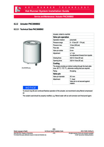
HOTRUNNERTECHNOLOGYHot Runner System Installation GuideService and Maintenance / Nozzle 12EX16 / 16EX22 SeriesDisassembly- Assembly Tools 12EX16 / 16EX22In this section the Stripping and Mounting Tool parts are identified with the numbers indicated in the following figure.Disassembly- Assembly Tools 12EX16Front Heater Disassembly Tool Complete AT12E-0101Pos.Part No.DescriptionT1.1AT12E-010101Heater Disassembly ToolType 01 for Nozzle 12EX16T1.2AT12E-010102Heater Disassembly ToolType 02 for Nozzle 12EX16T1.3AT12E-010103Heater Disassembly ToolType 03 for Nozzle 12EX16Doc003818.pngT1) Front Heater Assembly ToolAT12E-0102(T2) Nozzle TipAssembly toolAT12E-0103(T1) Nozzle TipAssembly toolAT12E-0104Doc005228.pngDoc005227.pngT3) Seal CapAssembly toolAT12E-0105Doc006971.pngDoc005209.pngMaster Language is EnglishENHot Runner System Installation GuideRESTRICTED: Property of Synventive.- 326 For limited third party distribution based on need and intended use.SVC-17-0001 EN-Rev11All rights reserved. Errors and omissions excepted 2019 Synventive Molding Solutions
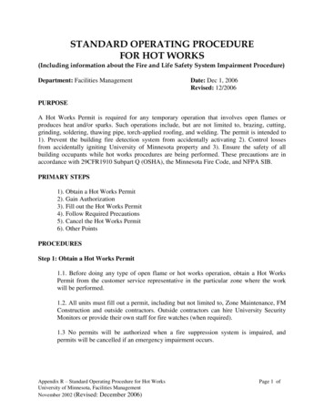
HOTRUNNERTECHNOLOGYHot Runner System Installation GuideService and Maintenance / Nozzle 12EX16 / 16EX22 SeriesDisassembly- Assembly Tools 16EX22Front Heater Disassembly Tool CompleteAT-HT-032-0101Pos.Part No.DescriptionT1.1AT-HT-032-010101Heater Disassembly ToolType 01 for Nozzle 16EX22T1.2AT-HT-032-010102Heater Disassembly ToolType 02 for Nozzle 16EX22T1.3AT-HT-032-010103Heater Disassembly ToolType 03 for Nozzle 16EX22Doc003818.pngT1) Front Heater Assembly ToolAT-HT-032-0102T2)Nozzle Tip - Assembly ToolAT-16 -040102Also used for the assembly of seal caps.Doc005228.pngT1)Nozzle Tip - Assembly ToolAT-16-040101Also used for the assembly of seal caps.Doc006971.pngDoc007735.pngMaster Language is EnglishENHot Runner System Installation GuideRESTRICTED: Property of Synventive.- 327 For limited third party distribution based on need and intended use.SVC-17-0001 EN-Rev11All rights reserved. Errors and omissions excepted 2019 Synventive Molding Solutions
HOTRUNNERTECHNOLOGYHot Runner System Installation GuideService and Maintenance / Nozzle 12EX16 / 16EX22 Series10.1.5.1 Nozzle Thermocouple 12EX16 / 16EX22Heaters with J-type and K-type thermocouples are available.The heating and the thermocouple of the frontheating (8) are independent heating elements and can bereplaced individually.The heating and the thermocouple of the rear heating element (4) are not separate, which means that thethermocouple must be replaced together with the rear heating element.Dismounting Thermocouple of the FrontheatingNOTICEFor dismounting of the thermocouple from nozzle heater, the nozzle heater must be dismantled from the nozzle.1) Lever the clamp (b) of the heating element with a screwdriver and pull thethermocouple (a) from its seat.2) Pull the top of the thermocouple (a) from the bracket of the nozzle heater (b).NOTICEThe thermocouple is pressed in.Doc005195.pngMounting Nozzle the Thermocouple of the FrontheatingColor Coding of ThermocouplesNOTICETake notice of the production and color identification of thermocouple cables.Synventive uses J and K type thermocouples. Their color coding is given in the following table.Table 1: International color coding for temperature sensorsTypeJKCoatingLitz wire “ ”Litz wire “-”International standard IEC 584-3Black Black- WhiteGreen Green- White1) Push the thermocouple (a) under thebracket on the nozzle heater (b).NOTICEThe fixing is needed to secure the position.A thermocouple (a) well-fixed in the holder(b) causes correct measured values.Doc005196.png2) Lever the clamp of the heating element with a screwdriver and fix thethermocouple (a) below the clamp (b) at the nozzle heater.Master Language is EnglishENHot Runner System Installation GuideRESTRICTED: Property of Synventive.- 328 For limited third party distribution based on need and intended use.SVC-17-0001 EN-Rev11All rights reserved. Errors and omissions excepted 2019 Synventive Molding Solutions
HOTRUNNERTECHNOLOGYHot Runner System Installation GuideService and Maintenance / Nozzle 12EX16 / 16EX22 Series10.1.
Hot Surfaces Hazard Contact between the skin and hot surfaces could result in burns. Use personal protective equipment, such as gloves, apron, sleeves and face protection, to guard against burns. When servicing or handling the hot runner system outside the manifold plates or the injection molding machine, care must be taken to heed the hot surface