Transcription
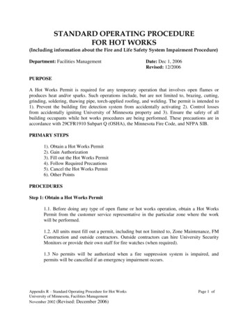
HOTRUNNERTECHNOLOGYHot Runner System Installation GuideService and Maintenance / Actuator PNC3008B028.2.2Actuator PNC3008B028.2.2.1 Technical Data PNC3008B02Actuator, bolted to manifoldValve pin operationOperation mediumpneumaticPressure range6 - 12 bar (87 - 174 psi)Pressure max.14 bar (203 psi)Flow rate2 l/minValve pin stroke8 mmAdjustment 1 mmvia adjustment threads from topsideClosing force424 N / 6 bar (87 psi)Opening force332 N / 6 bar (87 psi)CoolingDoc003006.pngThe design provides an indirect cooling through the back plate(max. 80 C / 175 F ), otherwise cooling lines are required.PipingNo piping.Valve pinValve pin diameterØ 3 mmAttachmentT - headValve pin is not secured againstrotation.NOTICETo ensure long life and continued flawless operation of the actuator, we recommend using filtered compressedair.The coolant used should be properly modified, e.g. filtered water with an anti-corrosion and frost-proof agent.Master Language is EnglishENHot Runner System Installation GuideRESTRICTED: Property of Synventive.- 143 For limited third party distribution based on need and intended use.SVC-17-0001 EN-Rev13All rights reserved. Errors and omissions excepted 2021 Synventive Molding Solutions
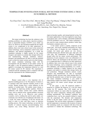
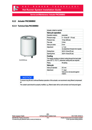
HOTRUNNERTECHNOLOGYHot Runner System Installation GuideService and Maintenance / Actuator PNC3008B028.2.2.2 Exploded View PNC3008B02This section describes the disassembly and reassembly process to replace seals.In this section the actuator parts are identified with the numbers indicated in the following figure, which shows the components.NOTICEAlways tighten the screws to the torques specified in the respective table (section 13).Actuator Parts - PNC3008B02No.Item(1)1Cylinder housingPNC3008CH01(2)1PistonPNC3008PI02(3)1Hanger screwPNC3008HS01(4)1Lock screwPNC3008LS01(5)1BufferPNC3008BU01(6)1Retaining ring for boresDIN472/34X1.5(7)1Seal Kit PNC3008PNC3008B01SK01(7.1)1Piston sealK30-30-22.5-3.2-VIOR(7.2)1Rod sealC1-1039-V3664(7.3)1Guiding elementFB2.3-1.5L41.5(7.4)1O-ring sealVIOR-26x2-FPM80(7.5)1O-ring sealVIOR-36x1.5-FPM80(7.6)1O-ring sealVIOR-19x1.5-FPM80(8)1Holding ringPNC3008HR01(9)2Hexagon socket cap screw DIN912-M4X14-12.9(10)2Hexagon socket set screw DIN914-M3X5-45H(11)1Cover Plate forPNC3008BPNC3008B-CP-01(optional)(12)4Hexagon socketcountersunk head capscrewDIN7991-M5X10-10.9(optional)(13)1Viton O-Ring 20.35 x 1.78 VIOR-20.35X1.78FPM80 greenFPM-80-G (optional)Doc006551.pngMaster Language is EnglishQty. DescriptionENHot Runner System Installation GuideRESTRICTED: Property of Synventive.- 144 For limited third party distribution based on need and intended use.SVC-17-0001 EN-Rev13All rights reserved. Errors and omissions excepted 2021 Synventive Molding Solutions
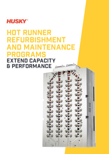
HOTRUNNERTECHNOLOGYHot Runner System Installation GuideService and Maintenance / Actuator PNC3008B028.2.2.3 Tools for Assembling, Disassembling and Adjusting the ActuatorThe following overview contains a list of special tools needed for the assembly and disassembly of the actuator and to replaceseals.The assembly and disassembly tools are identified with the numbers indicated in the following figure, which shows thecomponents in this section.Tools to Mount Actuator Seals andthe PistonNo.(T1)(T2)(T3)DescriptionItemSpreader sleeve ATCYL15Mounting coneATCYL14CalibrationATCYL13sleeve (cone 30)Valve Pin Disassembly Tool ATCYL16DescriptionNo.(T4.1) Adapter for valvepin ø 3 mm andø 3,8 mm(T4.2) Slice hammer(T4.3) Guid(T4.4) Stop CYL0104Assembly Tool ATCYL12DescriptionNo.(T5.1) Adjustment ToolTyp01(T5.2) Adjustment ToolTyp02(T5.3) Adjustment ToolTyp03(T5.4) Retaining ring(T5.5) Socket head 1DIN912-M4x30-12.9Doc003020.pngNOTICEThe tools ATCYL13, ATCYL14, ATCYL15 and ATCYL16 are not included with the Hot Runner System and mustbe ordered from Synventive separately.Master Language is EnglishENHot Runner System Installation GuideRESTRICTED: Property of Synventive.- 145 For limited third party distribution based on need and intended use.SVC-17-0001 EN-Rev13All rights reserved. Errors and omissions excepted 2021 Synventive Molding Solutions
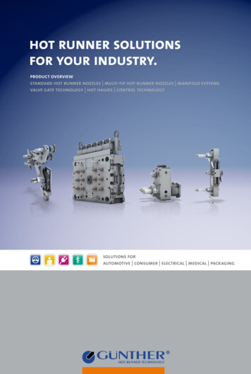
HOTRUNNERTECHNOLOGYHot Runner System Installation GuideService and Maintenance / Actuator PNC3008B028.2.2.4 Disassembling Actuator PNC3008B02NOTICEFor actuator disassemblythe lock screw (4) of thehanger screw (3) needs tobe loosened.1) Hold against turning: Piston (2) with theadjustment tool(T5.1). Hanger screw (3)with the hexagonsocket wrench (T6).At the same time loosenthe lock screw (4) with theassembly tool (T5.2) andring wrench (T7).Doc003060.png2) Unscrew hexagon socket set screws(10).Doc003061.pngMaster Language is EnglishENHot Runner System Installation GuideRESTRICTED: Property of Synventive.- 146 For limited third party distribution based on need and intended use.SVC-17-0001 EN-Rev13All rights reserved. Errors and omissions excepted 2021 Synventive Molding Solutions
HOTRUNNERTECHNOLOGYHot Runner System Installation GuideService and Maintenance / Actuator PNC3008B023) Slip the lug of the tool ATCYL1201(T5.1) into the gap of the piston (2).4) Tighten the piston (2) with toolATCYL1201 (T5.1) and flat wrench13 mm (T8).Doc003059.png5) With Hexagon socket wrench (T6)turn the hanger screw (3) clockwiseuntil the hanger screw (3) isunscrewed out of the piston (2).NOTICEThe actuator will be liftedfrom the holding ring (8)and will be separated fromthe valve pin and hangerscrew (3).Doc003062.pngMaster Language is EnglishENHot Runner System Installation GuideRESTRICTED: Property of Synventive.- 147 For limited third party distribution based on need and intended use.SVC-17-0001 EN-Rev13All rights reserved. Errors and omissions excepted 2021 Synventive Molding Solutions
HOTRUNNERTECHNOLOGYHot Runner System Installation GuideService and Maintenance / Actuator PNC3008B026) Loosen the hanger screw (3) from the valve gate pin (VP).Doc003055.png7) Remove the retaining ring (6).Doc003056.png8) Press the piston (2) and buffer (5) out of the cylinder housing (1).9) Dismount the two piston seal (7.1) elements. O-ring (7.1) (a) Sealing element (7.1) (b)10) Dismantling the valve pin (see section 9.1).Doc003058.pngMaster Language is EnglishENHot Runner System Installation GuideRESTRICTED: Property of Synventive.- 148 For limited third party distribution based on need and intended use.SVC-17-0001 EN-Rev13All rights reserved. Errors and omissions excepted 2021 Synventive Molding Solutions
HOTRUNNERTECHNOLOGYHot Runner System Installation GuideService and Maintenance / Actuator PNC3008B028.2.2.5 Assembling the Actuator PNC3008B02Lubrication of Piston and Ring SealsNOTICEFor lubrication use Krytox GPL205.To Lubricate the piston sliding surface is essentialfor the actuator life time.Doc003777.pngTo Lubricate the piston ring seals is helpful toassemble the actuator.Doc006315.pngInstallation of the Sealing Ring on the Piston1) Put the mounting cone (T2) on the piston (2).Doc003007.pngNOTICEAfter disassembly of the sealing elements, the original sealsshould be replaced.2) Mount the O-ring (7.1) (a) into the seal groove of the piston (2).3) Using the spreader sleeve (T1) and the mounting cone (T2), push thesealing element (7.1) (b) into the seal groove of the piston (2).NOTICEThe sealing element (7.1) (b) is placed in the seal grove of thepiston (2) above the O-ring (7.1) (a).Doc003008.pngMaster Language is EnglishENHot Runner System Installation GuideRESTRICTED: Property of Synventive.- 149 For limited third party distribution based on need and intended use.SVC-17-0001 EN-Rev13All rights reserved. Errors and omissions excepted 2021 Synventive Molding Solutions
HOTRUNNERTECHNOLOGYHot Runner System Installation GuideService and Maintenance / Actuator PNC3008B02Installation of the Piston into the Actuator Housing1) Degrease the piston sliding surface.2) Lubricate the piston sliding surface.Doc003777.png3) Insert the piston (2) into the calibration sleeve (T3).4) Place the calibration sleeve (T3) into the cylinder housing (1).5) Push the piston (2) into the cylinder housing.NOTICEThe calibration sleeve (T3) prevents damage to the piston seal(7.1).Doc003009.pngNOTICEAfter disassembly of the system, the original seals should bereplaced with new seals.6) Install the following seals at the buffer (5). Rod seal (7.2) Guiding element (7.3) O-ring seal (7.4)Doc003010.png7) Mount buffer (5) into the cylinder housing (1).8) Lock the buffer with the retaining ring (6).Doc003011.pngMaster Language is EnglishENHot Runner System Installation GuideRESTRICTED: Property of Synventive.- 150 For limited third party distribution based on need and intended use.SVC-17-0001 EN-Rev13All rights reserved. Errors and omissions excepted 2021 Synventive Molding Solutions
HOTRUNNERTECHNOLOGYHot Runner System Installation GuideService and Maintenance / Actuator PNC3008B029) Install the following seals at the actuator housing (1). Viton-ring seal (7.5) Viton-ring seal (7.6)Doc003185.pngMounting of the Actuator on the Manifold1) Mount actuator to the holding ring (8).2) Lubricate the thread of the hexagon socket set screws (10) with hightemperature assembly paste (anti-seize compound).NOTICEThis is an important measure to prevent thread corrosion dueto aggressive gases, which could be released during plasticsprocessing.3) Lock the actuator with hexagon socket set screws (10).4) Push piston (2) in closed position.NOTICEClosed position is when the top edge of the piston has adistance of 3 mm to the top edge of the actuator housing.Doc003013.png5) Mount the valve pin (VP) into the valve pin guide.6) Place the hanger screw (3) on the valve pin (VP) head.Doc003063.pngMaster Language is EnglishENHot Runner System Installation GuideRESTRICTED: Property of Synventive.- 151 For limited third party distribution based on need and intended use.SVC-17-0001 EN-Rev13All rights reserved. Errors and omissions excepted 2021 Synventive Molding Solutions
HOTRUNNERTECHNOLOGYHot Runner System Installation GuideService and Maintenance / Actuator PNC3008B028.2.2.6 Adjusting the Valve Pin to the Basic Position1) Screw the valve gate pin (VP) with the hanger screw (3) into the piston (2).Doc003014.png2) Hold the piston (2) against turningwith the adjustment tool (T5.1) anda flat wrench 13 mm (T8).Doc003059.pngMaster Language is EnglishENHot Runner System Installation GuideRESTRICTED: Property of Synventive.- 152 For limited third party distribution based on need and intended use.SVC-17-0001 EN-Rev13All rights reserved. Errors and omissions excepted 2021 Synventive Molding Solutions
HOTRUNNERTECHNOLOGYHot Runner System Installation GuideService and Maintenance / Actuator PNC3008B023) Adjust the valve pin with a hexagonsocket wrench (T6) as followed.4) Still hold the piston against turningwith the adjustment tool (T5.1).Doc003015.pngNOTICEThe basic setting for thevalve gate pin is 10 mmbetween the piston (2) topedge and the top edge fromthe hanger screw (3).5) Rotate the hanger screw (3) with ahexagon socket wrench (T6) into thepiston (2).NOTICEThe exact position for the valve pin (VP)has to be checked at the front of the valvepin - depends on the nozzle tip.The reason to unscrew the hanger screw(3) would be for valve pin maintenance orreplacement.If the deviation to the basic settingsof 10 mm is more than 0,5 mm, theadjustments do not correspond tothe parameters of the mold or do notcorrespond to the Synventive standard.Doc003016.pngMaster Language is EnglishENHot Runner System Installation GuideRESTRICTED: Property of Synventive.- 153 For limited third party distribution based on need and intended use.SVC-17-0001 EN-Rev13All rights reserved. Errors and omissions excepted 2021 Synventive Molding Solutions
HOTRUNNERTECHNOLOGYHot Runner System Installation GuideService and Maintenance / Actuator PNC3008B026) Wrap lock screw (4) with Teflon band (2 layer).7) Rotate the lock screw (4) with the assembly tool (T5.2) into the piston (2).Doc003017.tifNOTICEFor actuator assembly thelock screw (4) has to befastened against the hangerscrew (3).8) Hold against turning: Piston (2) with the adjustmenttool Typ01 (T5.1). Hanger screw (3) with thehexagon socket wrench (T6).9) At the same time tighten the lock screw(4) with the assembly tool (T5.2).Doc003018.pngMaster Language is EnglishENHot Runner System Installation GuideRESTRICTED: Property of Synventive.- 154 For limited third party distribution based on need and intended use.SVC-17-0001 EN-Rev13All rights reserved. Errors and omissions excepted 2021 Synventive Molding Solutions
HOTRUNNERTECHNOLOGYHot Runner System Installation GuideService and Maintenance / Actuator PNC3008B028.2.2.7 Valve Pin Height Adjustment PNC3008B02Precondition for the following steps are to be performed with the Hot Runner installed in themold, and the system at operating temperature.Hot Surfaces HazardContact between the skin and hot surfaces could result in burns.Use personal protective equipment, such as gloves, apron, sleeves and faceprotection, to guard against burns.When servicing or handling the hot runner system outside the manifold platesor the injection molding machine, care must be taken to heed the hot surfaceexposure warnings.For first aid contact your medical / safety representingValve Pin Adjustment Tool KitNo.DescriptionItem(T5.1) Adjustment Tool ATCYL1201Typ01(T5.2) Adjustment Tool ATCYL1202Typ02(T5.3) Adjustment Tool ATCYL1203Typ03(T5.4) Retaining ringDIN471-15x1(T5.5) Socket headcap screwsDIN912-M4x30-12.9Doc003020.pngMaster Language is EnglishENHot Runner System Installation GuideRESTRICTED: Property of Synventive.- 155 For limited third party distribution based on need and intended use.SVC-17-0001 EN-Rev13All rights reserved. Errors and omissions excepted 2021 Synventive Molding Solutions
HOTRUNNERTECHNOLOGYHot Runner System Installation GuideService and Maintenance / Actuator PNC3008B02Valve Pin Adjustment at mounted Hot Runner SystemHot Surfaces HazardContact between the skin and hot surfaces could result in burns.NOTICEThe actuator is covered with a plate, containing thepneumatic access to the actuator.1) Enable access to the actuator.Doc003021.png2) Slip the lug of the tool ATCYL1201(T5.1) into the gap of the piston.Doc003064.pngMaster Language is EnglishENHot Runner System Installation GuideRESTRICTED: Property of Synventive.- 156 For limited third party distribution based on need and intended use.SVC-17-0001 EN-Rev13All rights reserved. Errors and omissions excepted 2021 Synventive Molding Solutions
HOTRUNNERTECHNOLOGYHot Runner System Installation GuideService and Maintenance / Actuator PNC3008B02NOTICEThe piston is in the closedposition, when the top edge ofthe piston (2) has a distanceof 3 mm to the top edge of theactuator housing (1).3) Push the fixed piston (2) forward to theclose position.4) Place the retaining ring (T5.4).at the toolATCYL1201 (T5.1).5) Place the ATCYL1203 (T5.3) onthe retaining ring (T5.4) at the toolATCYL1201 (T5.1).6) Fix the piston (2) against upstrokeand rotation with the socket head capscrews (T5.5).NOTICEUse torque wrench withwrench insert and the torquesindicated in the torque table(section 13).Doc003022.png7) Fix the hanger screw (3) with the socketwrench (T6).8) Slacken the lock screw (4) with theadjustment tool ATCYL1202 (T5.2) andring wrench (T7) attached to it.Legend to Doc003023.png(T5.1) Adjustment tool Typ01- ATCYL1201(T5.2) Adjustment tool Typ02- ATCYL1202(T5.3) Adjustment tool Typ03- ATCYL1203(3)Hanger screw(4)Lock screw(T6)Socket wrench HEX 4(T7)Ring wrench HEX 7Doc003023.pngMaster Language is EnglishENHot Runner System Installation GuideRESTRICTED: Property of Synventive.- 157 For limited third party distribution based on need and intended use.SVC-17-0001 EN-Rev13All rights reserved. Errors and omissions excepted 2021 Synventive Molding Solutions
HOTRUNNERTECHNOLOGYHot Runner System Installation GuideService and Maintenance / Actuator PNC3008B029) To adjust valve pin position: Fix the lock screw (4) with theadjustment tool ATCYL2102(T5.2) and a ring wrench (T7). Turn the hanger screw (3)with the socket wrench (T6).NOTICEThe screw pitch is 1 mm (righthand thread).Doc003024.pngDoc003017.tifNOTICEThe lock screw (4) has tobe wraped with Teflon tape(2 layer).After several adjustmentsreplace the Teflon tape.To fix the vale pin position:10) Secure with the hexagon socket wrench(T6) the hanger screw (3) againstturning.11) Tighten the lock screw (4) with theassembly tool ATCYL2102 (T5.2) and aring wrench (T7).NOTICEThe reason to unscrew thehanger screw (3) would befor valve pin maintenance orreplacement.Doc003025.pngMaster Language is EnglishENHot Runner System Installation GuideRESTRICTED: Property of Synventive.- 158 For limited third party distribution based on need and intended use.SVC-17-0001 EN-Rev13All rights reserved. Errors and omissions excepted 2021 Synventive Molding Solutions
HOTRUNNERTECHNOLOGYHot Runner System Installation GuideService and Maintenance / Actuator PNC3008B02NOTICEFor the control of the valve pins, a pneumatic system isinstalled.12) In case where the clamping plate has an opening for the valve pinadjustment, the opening must be capped airtight.Doc003026.pngMaster Language is EnglishENHot Runner System Installation GuideRESTRICTED: Property of Synventive.- 159 For limited third party distribution based on need and intended use.SVC-17-0001 EN-Rev13All rights reserved. Errors and omissions excepted 2021 Synventive Molding Solutions
Master Language is English Hot Runner System Installation Guide SVC-17-0001EN-Rev13 H O T R U N N E R T E C H N O L O G Y