Transcription
CH A P T E R9Configuring Access PointsThis chapter describes how to configure access points in the Cisco WCS database. This chapter containsthe following sections: Setting AP Failover Priority, page 9-1 Configuring Global Credentials for Access Points, page 9-2 Configuring Ethernet Bridging and Ethernet VLAN Tagging, page 9-3 Autonomous to Lightweight Migration Support, page 9-9 Configuring Access Points, page 9-17 Configuring Access Point Radios for Tracking Optimized Monitor Mode, page 9-33 Searching Access Points, page 9-35 Viewing Mesh Link Details, page 9-36 Viewing or Editing Rogue Access Point Rules, page 9-36 Configuring Spectrum Experts, page 9-37 OfficeExtend Access Point, page 9-39 Configuring Link Latency Settings for Access Points, page 9-40Setting AP Failover PriorityWhen a controller fails, the backup controller configured for the access point suddenly receives a numberof discovery and join requests. This may cause the controller to reach a saturation point and reject someof the access points.By assigning priority to an access point, you have some control over which access points are rejected.In a failover situation when the backup controller is saturated, the higher priority access points areallowed to join the backup controller by disjoining the lower priority access points.To configure priority settings for access points, you must first enable the AP Priority feature. To enablethe AP Priority feature, follow these steps:Step 1Choose Configure Controllers.Step 2Click the IP address of the applicable controller.Step 3From the left sidebar menu, choose System General.Step 4From the AP Failover Priority drop-down list, choose Enable.Cisco Wireless Control System Configuration GuideOL-21743-019-1
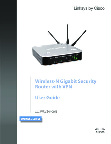
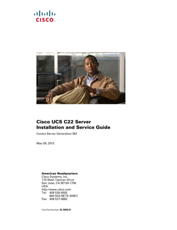
Chapter 9Configuring Access PointsConfiguring Global Credentials for Access PointsTo then configure an access point’s priority, refer to “Configuring Access Points” section on page 9-17.Configuring Global Credentials for Access PointsCisco autonomous access points are shipped from the factory with Cisco as the default enable password.This password allows users to log into the non-privileged mode and execute show and debug commands,posing a security threat. The default enable password must be changed to prevent unauthorized accessand to enable users to execute configuration commands from the access point’s console port.In WCS and controller software releases prior to 5.0, you can set the access point enable password onlyfor access points that are currently connected to the controller. In WCS and controller software release5.0, you can set a global username, password, and enable password that all access points inherit as theyjoin a controller. This includes all access points that are currently joined to the controller and any thatjoin in the future. When you are adding an access point, you can also choose to accept this globalusername and password or override it on a per-access point basis and assign a unique username,password, and enable password. See the “Configuring Access Point Templates” section on page 12-113to see where the global password is displayed and how it can be overridden on a per-access point basis.Also in controller software release 5.0, after an access point joins the controller, the access point enablesconsole port security, and you are prompted for your username and password whenever you log into theaccess point’s console port. When you log in, you are in non-privileged mode, and you must enter theenable password in order to use the privileged mode.NoteThese controller software release 5.0 features are supported on all access points that have been convertedto lightweight mode, except the 1100 series. VxWorks access points are not supported.The global credentials that you configure on the controller are retained across controller and access pointreboots. They are overwritten only if the access point joins a new controller that is configured with aglobal username and password. If the new controller is not configured with global credentials, the accesspoint retains the global username and password configured for the first controller.NoteYou need to keep careful track of the credentials used by the access points. Otherwise, you might not beable to log into an access point’s console port. If necessary, you can clear the access point configurationto return the access point username and password to the default setting.Follow these steps to establish a global username and password.Step 1Choose Configure Controllers or Configure Access Points.Step 2Choose an IP address of a controller with software release 5.0 or later or choose an access pointassociated with software release 5.0 or later.Step 3Choose System AP Username Password from the left sidebar menu. The AP Username Passwordpage appears (see Figure 9-1).Cisco Wireless Control System Configuration Guide9-2OL-21743-01
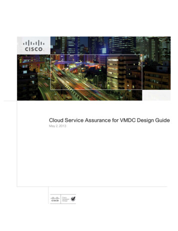
Chapter 9Configuring Access PointsConfiguring Ethernet Bridging and Ethernet VLAN TaggingFigure 9-1AP Username Password PageStep 4In the AP Username text box, enter the username that is to be inherited by all access points that join thecontroller.Step 5In the AP Password text box, enter the password that is to be inherited by all access points that join thecontroller. Re-enter in the Confirm AP Password text box.Step 6For Cisco autonomous access points, you must also enter and confirm an enable password. In the APEnable Password text box, enter the enable password that is to be inherited by all access points that jointhe controller. Re-enter in the Confirm Enable Password text box.Step 7Click Save.Configuring Ethernet Bridging and Ethernet VLAN TaggingEthernet bridging is used in two mesh network scenarios:1.NotePoint-to-point and point-to-multipoint bridging between MAPs (untagged packets). A typicaltrunking application might be bridging traffic between buildings within a campus (see Figure 9-2).You do not need to configure VLAN tagging to use Ethernet bridging for point-to-point andpoint-to-multipoint bridging deployments.Cisco Wireless Control System Configuration GuideOL-21743-019-3
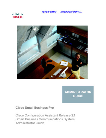
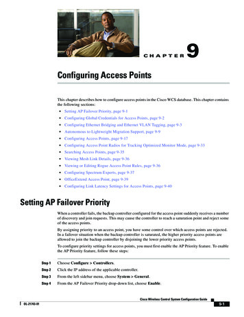
Chapter 9Configuring Access PointsConfiguring Ethernet Bridging and Ethernet VLAN TaggingPoint-to-Multipoint Bridging148439Figure 9-22.Ethernet VLAN tagging allows specific application traffic to be segmented within a wireless meshnetwork and then forwarded (bridged) to a wired LAN (access mode) or bridged to another wirelessmesh network (trunk mode).A typical public safety access application using Ethernet VLAN tagging is placement of videosurveillance cameras at various outdoor locations within a city. Each of these video cameras has a wiredconnection to a MAP. The video of all these cameras is then streamed across the wireless backhaul to acentral command station on a wired network (see Figure 9-3).Cisco Wireless Control System Configuration Guide9-4OL-21743-01
Chapter 9Configuring Access PointsConfiguring Ethernet Bridging and Ethernet VLAN TaggingFigure 9-3Ethernet VLAN TaggingControllerRoot APRoot APRoot APMesh APMesh APMesh APMesh APMesh APEthernetclientCameraMesh APEthernetclientCameraEthernetclient251053VLAN RVLAN GWired trunk links11a bridge trunk linksEthernet VLAN Tagging Guidelines For security reasons, the Ethernet port on a mesh access point (RAP and MAP) is disabled bydefault. It is enabled by configuring Ethernet Bridging on the mesh access point port. You must enable Ethernet bridging on all the access points in the mesh network to allow EthernetVLAN Tagging to operate. You must set VLAN Mode as non-VLAN transparent (global mesh parameter). See “ConfiguringEthernet Bridging and Ethernet VLAN Tagging” section on page 9-3.– VLAN transparent is enabled by default. To set as non-VLAN transparent, you must unselectthe VLAN transparent option in the Global Mesh Parameters page. VLAN configuration on a mesh access point is only applied if all the uplink mesh access points areable to support that VLAN.Cisco Wireless Control System Configuration GuideOL-21743-019-5
Chapter 9Configuring Access PointsConfiguring Ethernet Bridging and Ethernet VLAN Tagging– If uplink access points are not able to support the VLAN, then the configuration is stored ratherthan applied. VLAN tagging can only be configured on Ethernet interfaces.– On 152x mesh access points, use three of the four ports as secondary Ethernet interfaces: port0-PoE in, port 1-PoE out, and port 3- fiber. You cannot configure Port 2 - cable as a secondaryEthernet interface.– In Ethernet VLAN tagging, port 0-PoE in on the RAP connects the trunk port of the switch ofthe wired network. Port 1-PoE out on the MAP connects external devices such as video cameras. Backhaul interfaces (802.11a radios) act as primary Ethernet interfaces. Backhauls function astrunks in the network and carry all VLAN traffic between the wireless and wired network. You arenot required to configure the primary Ethernet interface. You must configure the switch port in the wired network that is attached to the RAP (port 0–PoE in)to accept tagged packets on its trunk port. The RAP forwards all tagged packets received from themesh network to the wired network. Configuration to support VLAN tagging on the 802.11a backhaul Ethernet interface is not requiredwithin the mesh network.– This includes the RAP uplink Ethernet port. The required configuration happens automaticallyusing a registration mechanism.– Any configuration changes to an 802.11a Ethernet link acting as a backhaul are ignored, and awarning results. When the Ethernet link no longer functions as a backhaul, the modifiedconfiguration is applied. You cannot configure VLANs on port-02-cable modem port of a 152x access point. ConfigureVLANs on ports 0 (PoE-in), 1 (PoE-out), and 3 (fiber). If bridging between two MAPs, enter the distance (mesh range) between the two access points thatare bridging. (Not applicable to applications in which you are forwarding traffic connected to theMAP to the RAP, access mode) Each sector supports up to 16 VLANs; therefore, the cumulative number of VLANs supported by aRAP’s children (MAPs) cannot exceed 16. Ethernet ports on access points function as normal, access, or trunk ports in an Ethernet taggingdeployment.– Normal mode–In this mode, the Ethernet interface is VLAN-transparent by default and does notaccept or send any tagged packets. Tagged frames from clients are dropped. Untagged framesare forwarded to the native VLAN on the RAP trunk port.– Access mode–In this mode only untagged packets are accepted. You must tag all packets witha user-configured VLAN called access-VLAN. For this mode to take effect, the global VLANmode should be non-VLAN transparent.Use this option for applications in which information is collected from devices connected to theMAP such as cameras or PCs and then forwarded to the RAP. The RAP then applies tags andforwards traffic to a switch on the wired network.– Trunk mode—This mode requires the user to configure a native VLAN and an allowed VLANlist (no defaults). In this mode, both tagged and untagged packets are accepted. You can acceptuntagged packets and tag them with the user-specified native VLAN. You can accept taggedpackets if they are tagged with a VLAN in the allowed VLAN list. For this mode to take effect,the global VLAN mode should be non-VLAN transparent.Use this option for bridging applications such as forwarding traffic between two MAPs residenton separate buildings within a campus.Cisco Wireless Control System Configuration Guide9-6OL-21743-01
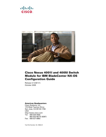
Chapter 9Configuring Access PointsConfiguring Ethernet Bridging and Ethernet VLAN Tagging The switch port connected to the RAP must be a trunk.– The trunk port on the switch and the RAP trunk port must match. A configured VLAN on a MAP Ethernet port cannot function as a Management VLAN. The RAP must always connect to the native VLAN (ID 1) on a switch.– The RAP’s primary Ethernet interface is by default the native VLAN of 1.Enabling Ethernet Bridging and VLAN TaggingFollow these steps to enable Ethernet Bridging and VLAN tagging on a RAP or MAP.Step 1Choose Configure Access Points.Step 2Click the name of the mesh access point for which you want to enable Ethernet bridging. A configurationpage for the access point appears.Step 3In the Bridging Information section, choose the appropriate backhaul rate from the Data Rate drop-downlist. The default value is 24 Mbps for the 802.11a backhaul interface.Step 4In the Bridging Information section, choose Enable from the Ethernet Bridging drop-down list.Step 5Click the appropriate Ethernet interface link (such as FastEthernet or gigabitEthernet1). (SeeFigure 9-4.)Figure 9-4Step 6Configure Access Points AP Name PageWithin the Ethernet interface page, perform one of the following (see Figure 9-5):Cisco Wireless Control System Configuration GuideOL-21743-019-7
Chapter 9Configuring Access PointsConfiguring Ethernet Bridging and Ethernet VLAN TaggingFigure 9-5Notea.Access Point Ethernet Interface PageThe configuration options vary for each of the VLAN modes (normal, access, and trunk).If you are configuring a MAP and RAP normal ports and chose FastEthernet0, choose Normal fromthe VLAN Mode drop-down list.In this mode, the Ethernet interface is VLAN-transparent by default and does not accept or send anytagged packets. Tagged frames from clients are dropped. Untagged frames are forwarded to thenative VLAN on the RAP trunk port.b.c.If you are configuring a MAP access port and chose gigabitEthernet1 (port 1-PoE out),1.Choose Access from the VLAN Mode drop-down list.2.Enter a VLAN ID. The VLAN ID can be any value between 1 and 4095.3.Click Save.NoteVLAN ID 1 is not reserved as the default VLAN.NoteA maximum of 16 VLANs in total are supported across all of a RAP’s subordinate MAPs.If you are configuring a RAP or MAP trunk port and chose gigabitEthernet0 (or FastEthernet0)(port 0-PoE in),1.Choose trunk from the VLAN Mode drop-down list.2.Enter a native VLAN ID for incoming traffic. The native VLAN ID can be any value between 1and 4095. Do not assign any value assigned to a user-VLAN (access).3.Enter a trunk VLAN ID for outgoing traffic and click Add.The added trunk appears in the summary column of allowed VLAN IDs.If forwarding untagged packets, do not change the default trunk VLAN ID value of zero (suchas MAP-to-MAP bridging, campus environment).If forwarding tagged packets, enter a VLAN ID (1 to 4095) that is not already assigned (suchas RAP to switch on wired network).Cisco Wireless Control System Configuration Guide9-8OL-21743-01
Chapter 9Configuring Access PointsAutonomous to Lightweight Migration SupportNote4.To remove a VLAN from the list, click Delete.Click Save.NoteAt least one mesh access point must be set to RootAP in the mesh network.Autonomous to Lightweight Migration SupportThe autonomous to lightweight migration support feature provides a common application (WCS) fromwhich you can perform basic monitoring of autonomous access points along with current lightweightaccess points. The following autonomous access points are supported: Cisco Aironet 1130 Access Point Cisco Aironet 1200 Access Point Cisco Aironet 1240 Access Point Cisco Aironet 1310 Bridge Cisco Aironet 1410 BridgeYou may also choose to convert autonomous access points to lightweight. Once an access point isconverted to lightweight, the previous status or configuration of the access point is not retained.From WCS, the following functions are available when managing autonomous access points: Adding Autonomous access points Configuring autonomous access points Viewing current autonomous access points from the Monitor Access Points page (see MonitoringAccess Points for more information) Adding and viewing autonomous access points from the Monitor Maps page (see Maps for moreinformation) Monitoring associated alarms Performing an autonomous access point background task– Checks the status of autonomous access points managed by WCS.– Generates a critical alarm when an unreachable autonomous access point is detected. Running reports on autonomous access points– See Reports Inventory Reports and Reports Client Reports Client Count for moreinformation Supporting autonomous access points in Work Group Bridge (WGB) mode Migrating autonomous access points to lightweight access pointsCisco Wireless Control System Configuration GuideOL-21743-019-9
Chapter 9Configuring Access PointsAutonomous to Lightweight Migration SupportAdding Autonomous Access Points to WCSFrom WCS, the following methods are available for adding autonomous access points: Add autonomous access points by Device information (IP addresses and credentials). Add autonomous access points by CSV file.Adding Autonomous Access Points by Device InformationAutonomous access points can be added to WCS by device information using comma-separated IPaddresses and credentials.To add autonomous access points using device information, follow these steps:Step 1Choose Configure Access Points.Step 2From the Select a command drop-down list, choose Add Autonomous APs.Step 3Click Go.Step 4Select Device Info from the Add Format Type drop-down list.Step 5Enter comma-separated IP addresses of autonomous access points.Step 6Select the Verify Telnet/SSH Credentials check box if you want this controller to verify Telnet/SSHcredentials.Step 7Enter the SNMP parameters including version number, number of retries, and timeout in seconds.Step 8(Optional) Enter Telnet credentials for migration.Step 9NoteThe Telnet credentials are required to convert the access points from autonomous to unified andfor access point CLI templates.NoteIf the autonomous access point already exists, WCS updates the credentials (SNMP and Telnet)to the existing device.Click OK.Adding Autonomous Access Points by CSV FileAutonomous access points can be added to WCS using a CSV file exported from WLSE.To add autonomous access points using a CSV file, follow these steps:Step 1Choose Configure Access Points.Step 2From the Select a Command drop-down list, choose Add Autonomous APs.Step 3Click Go.Step 4Select File from the Add Format Type drop-down list.Step 5Enter or browse to the applicable CSV file.Cisco Wireless Control System Configuration Guide9-10OL-21743-01
Chapter 9Configuring Access PointsAutonomous to Lightweight Migration SupportThe sample CSV files for V2 devices are as follows:ip address, network mask, snmp version, snmp community, snmpv3 user name, snmpv3 auth type,snmpv3 auth password, snmpv3 privacy type, snmpv3 privacy password, snmp retries,snmp timeout,telnet username,telnet password,telnet retries,telnet 3,4,Cisco,Cisco,2,10The sample CSV files for V3 devices are as follows:ip address, network mask, snmp version, snmpv3 user name, snmpv3 auth type,snmpv3 auth password, snmpv3 privacy type, snmpv3 privacy password, snmp retries,snmp timeout,telnet username,telnet password,telnet retries,telnet ,4,Cisco,Cisco,2,10The CSV files can contain the following fields:Step 6 ip address network mask snmp version snmp community snmpv3 user name snmpv3 auth type snmpv3 auth password snmpv3 privacy type snmpv3 privacy password snmp retries snmp timeout telnet username telnet password enable password telnet retries telnet timeoutClick OK.To remove an autonomous access point from WCS:Step 1Select the check boxes of the access points you want to remove.Step 2Select Remove APs from the Select a Command drop-down list.Viewing Autonomous Access Points in WCSOnce added, the autonomous access points can be viewed on the Monitor Access Points page.Cisco Wireless Control System Configuration GuideOL-21743-019-11
Chapter 9Configuring Access PointsAutonomous to Lightweight Migration SupportClick the autonomous access point to view more detailed information such as:– Operational status of the access points– Key attributes including radio information, channel, power, and number of clients on the radio– CDP neighbored informationThe autonomous access points can also be viewed in Monitor Maps.They can be added to a floor area by choosing Monitor Maps floor area and selecting Add AccessPoints from the Select a Command drop-down list.Downloading Images to Autonomous Access PointsLightweight access point images are bundled with controller images and managed by the controller.Autonomous access point images must be handled by a NMS system such as WLSE, CiscoWorks, orWCS. Follow these steps to download images to autonomous access points.Step 1Choose Configure Access Points.Step 2Click the check box of the autonomous access point to which you want to download an image. The APType column displays whether the access point is autonomous or lightweight.Step 3From the Select a command drop-down list, choose Download Autonomous AP Image. The imagedownload page appears.To ensure that no more than ten access points are selected for download, a check is made. The imagemust be compatible with all of the selected access points. Scheduling an immediate task initiates theimage download. It is periodically refreshed.Work Group Bridge (WGB) ModeWireless Group Bridge (WGB) mode is a special mode where an autonomous access point functions asa wireless client and connects to a lightweight access point. The WGB and its wired clients are listed asclient in WCS if the AP mode is set to Bridge, and the access point is bridge capable.To view a list of all WCS clients that are WGBs, choose Monitor Clients. At the Show drop-downlist, choose WGB Clients, and click Go. The Clients (detected as WGBs) page appears. Click a User toview detailed information regarding a specific WGB and its wired clients.NoteThe WCS provides WGB client information for the autonomous access point whether or not it ismanaged by the WCS. If the WGB access point is also managed by the WCS, WCS provides basicmonitoring functions for the access point similar to other autonomous access points.Autonomous Access Point to Lightweight Access Point MigrationTo make a transition from an Autonomous solution to a Unified architecture, autonomous access pointsmust be converted to lightweight access points. The migration utility is available in the Configure Autonomous AP Migration Templates page where existing templates are listed.The Autonomous AP Migration Templates list page displays the following information:Cisco Wireless Control System Configuration Guide9-12OL-21743-01
Chapter 9Configuring Access PointsAutonomous to Lightweight Migration Support Name—The template name. Description—The description of template. AP Count—The number of autonomous access points selected for migration. Schedule Run—The time at which the task is scheduled to run. Status—Indicates one of the following task statuses:– Not initiated—The template is yet to start the migration and will start at the scheduled time.When the template is in this state, you can click the Name link to edit the template.– Disabled—The template is disabled and will not run at the scheduled time. This is the defaultstate for a template when it is created without selecting any autonomous access points. Whenthe template is in this state, you can click the Name link to edit the template.– Expired—The template did not run at the scheduled time (this may be due to the WCS serverbeing down). When the template is in this state, you can click the Name link to edit the template.– Enabled—The template is yet to start the migration and will start at the scheduled time. Whenthe template is in this state, you can click the Name link to edit the template.– In progress—The template is currently converting the selected autonomous access points toCAPWAP. When the template is in this state, you cannot edit the template by clicking the Namelink.– Success—The template has completed the migration of autonomous access point to CAPWAPsuccessfully. When the template is in this state, you cannot edit the template by clicking theName link.– Failure—The template failed to migrate all the selected autonomous access point to CAPWAP.You can check the detailed status about the failures by using the View Migration Status page.When the template is in this state, you cannot edit the template by clicking the Name link.– Partial Success—The template failed to migrate a subset of the selected autonomous accesspoint to CAPWAP. You can check the detailed status about the failures by using the ViewMigration Status page. When the template is in this state, you cannot edit the template byclicking the Name link.NoteOnce an access point is converted to lightweight, the previous status or configuration of the access pointis not retained.From the Select a command drop-down list, the following functions can be performed: Add Template—Allows you to provide necessary information for migration. Delete Templates—Allows you to delete a current template. View Migration Report—Allows you to view information such as AP address, migration status (inprogress or fail), timestamp, and a link to detailed logs. View Current Status—Allows you to view the progress of the current migration (updated every threeseconds).NoteWhen you migrate an already-managed autonomous access point to lightweight, its location andantenna information is migrated as well. You do not need to re-enter the information. WCSautomatically removes the autonomous access point after migration.Cisco Wireless Control System Configuration GuideOL-21743-019-13
Chapter 9Configuring Access PointsAutonomous to Lightweight Migration Support View Migration Analysis Summary—Lists the pass or fail status as required for an access pointconversion. Only those access points with all criteria as pass are eligible for conversion.Viewing the Migration Analysis SummaryFollow these steps to view the Migration Analysis Summary.NoteYou can also view the migration analysis summary by choosing Tools Migration Analysis.Step 1Choose Configure Autonomous AP Migration Templates.Step 2Click View Migration Analysis Summary from the Select a command drop-down list, and click Go.The Migration Analysis Summary page appears.The autonomous access points are eligible for migration only if all the criteria have a pass status. A redX designates ineligibility, and a green checkmark designates eligibility. These columns represent thefollowing: Privilege 15 Criteria—The Telnet credential provided as part of the autonomous access pointdiscovery must be privilege 15. Software Version Criteria—Conversion is supported only from Cisco IOS 12.3(7)JA releasesexcluding 12.3(11)JA, 12.3(11)JA1, 12.3(11)JA2, and 12.3(11)JA3. Role Criteria—A wired connection between the access point and controller is required in order tosend the association request; therefore, the following autonomous access point roles are required:– root– root access point– root fallback repeater– root fallback shutdown– root access point only Radio Criteria—In dual-radio access points, the conversion can happen even if only one radio is ofthe supported type.Upgrading Autonomous Access PointsYou can choose to upgrade the autonomous access points manually or automatically. From the MigrationAnalysis page, you can select the access point with the software version listed as failed and chooseUpgrade Firmware (Manual or Automatic) from the Select a command drop-down list. This processupgrades the autonomous firmware image of the Cisco IOS access point to a supported version.WCS uses a Telnet-based connection to upgrade the access point firmware. If you choose the automaticoption, the internal TFTP server is used with the default images present in WCS. The default images asper device type are as follows: ap801-k9w7-tar.124-10b.JA3.tar c1100-k9w7-tar.123-7.JA5.tar c1130-k9w7-tar.123-7.JA5.tar c1200-k9w7-tar.123-7.JA5.tarCisco Wireless Control System Configuration Guide9-14OL-21743-01
Chapter 9Configuring Access PointsAutonomous to Lightweight Migration Support c1240-k9w7-tar.12307.JA5.tar c1250-k9w7-tar.124-10b.JA3.tar c1310-k9w7-tar.123-7.JA5.tarIf you choose the manual option, an additional screen with TFTP server IP, file path, and file path nameappears. The final page is the report page.Changing Station Role to Root ModeBecause a wired connection between the access point and controller is required in order to send theassociation request, the autonomous access point must be assigned the appropriate role. If the role showsas ineligible, you can choose Change Station Role to Root Mode from the Select a commanddrop-down list.Running Migration AnalysisYou can choose Run Migration Analysis from the Select a command drop-down list of the MigrationAnalysis Summary page. The resulting migration analysis summary shows the current status of differentcriteria. Initially, migration analysis is run automatically when the access point is discovered.Generating the Migration Analysis ReportYou can choose View Migration Analysis Report from the Select a command drop-down list of theMigration Analysis Summary page to generate a report. The report includes the following: Access point address Status Timestamp Access point logsAdding/Modifying a Migration TemplateIf you want to add a migration template, choose Add Template from the Select a command drop-downpage of the Configure Autonomous AP Migration Templates page.To modify an existing template, click the template name from the summary list.Enter or modify the following migration parameters:General Name—User-defined name of this migration template. Description—Brief description to help you identify the migration template. DHCP Support—Ensures that after the conversion every access point gets an IP from the DHCPserver. Retain AP HostName—Allows you to retain the same hostname for this access point.Upgrade OptionsCisco Wireless Control System Configuration GuideOL-21743-01
In WCS and controller software rele ases prior to 5.0, you can set the access point enable password only for access points that are currently connected to the controller. In WCS and controller software release 5.0, you can set a global username, password, and enab le password that all access points inherit as they join a controller.