Transcription
Cisco UCS C22 ServerInstallation and Service GuideCovers Server Generation M3May 09, 2013Americas HeadquartersCisco Systems, Inc.170 West Tasman DriveSan Jose, CA 95134-1706USAhttp://www.cisco.comTel: 408 526-4000800 553-NETS (6387)Fax: 408 527-0883Text Part Number: OL-26646-01
THE SPECIFICATIONS AND INFORMATION REGARDING THE PRODUCTS IN THIS MANUAL ARE SUBJECT TO CHANGE WITHOUT NOTICE. ALLSTATEMENTS, INFORMATION, AND RECOMMENDATIONS IN THIS MANUAL ARE BELIEVED TO BE ACCURATE BUT ARE PRESENTED WITHOUTWARRANTY OF ANY KIND, EXPRESS OR IMPLIED. USERS MUST TAKE FULL RESPONSIBILITY FOR THEIR APPLICATION OF ANY PRODUCTS.THE SOFTWARE LICENSE AND LIMITED WARRANTY FOR THE ACCOMPANYING PRODUCT ARE SET FORTH IN THE INFORMATION PACKET THATSHIPPED WITH THE PRODUCT AND ARE INCORPORATED HEREIN BY THIS REFERENCE. IF YOU ARE UNABLE TO LOCATE THE SOFTWARE LICENSEOR LIMITED WARRANTY, CONTACT YOUR CISCO REPRESENTATIVE FOR A COPY.The following information is for FCC compliance of Class A devices: This equipment has been tested and found to comply with the limits for a Class A digital device, pursuantto part 15 of the FCC rules. These limits are designed to provide reasonable protection against harmful interference when the equipment is operated in a commercialenvironment. This equipment generates, uses, and can radiate radio-frequency energy and, if not installed and used in accordance with the instruction manual, may causeharmful interference to radio communications. Operation of this equipment in a residential area is likely to cause harmful interference, in which case users will be requiredto correct the interference at their own expense.The following information is for FCC compliance of Class B devices: This equipment has been tested and found to comply with the limits for a Class B digital device, pursuantto part 15 of the FCC rules. These limits are designed to provide reasonable protection against harmful interference in a residential installation. This equipment generates,uses and can radiate radio frequency energy and, if not installed and used in accordance with the instructions, may cause harmful interference to radio communications.However, there is no guarantee that interference will not occur in a particular installation. If the equipment causes interference to radio or television reception, which can bedetermined by turning the equipment off and on, users are encouraged to try to correct the interference by using one or more of the following measures: Reorient or relocate the receiving antenna.Increase the separation between the equipment and receiver.Connect the equipment into an outlet on a circuit different from that to which the receiver is connected.Consult the dealer or an experienced radio/TV technician for help.Modifications to this product not authorized by Cisco could void the FCC approval and negate your authority to operate the product.The Cisco implementation of TCP header compression is an adaptation of a program developed by the University of California, Berkeley (UCB) as part of UCB’s publicdomain version of the UNIX operating system. All rights reserved. Copyright 1981, Regents of the University of California.NOTWITHSTANDING ANY OTHER WARRANTY HEREIN, ALL DOCUMENT FILES AND SOFTWARE OF THESE SUPPLIERS ARE PROVIDED “AS IS” WITHALL FAULTS. CISCO AND THE ABOVE-NAMED SUPPLIERS DISCLAIM ALL WARRANTIES, EXPRESSED OR IMPLIED, INCLUDING, WITHOUTLIMITATION, THOSE OF MERCHANTABILITY, FITNESS FOR A PARTICULAR PURPOSE AND NONINFRINGEMENT OR ARISING FROM A COURSE OFDEALING, USAGE, OR TRADE PRACTICE.IN NO EVENT SHALL CISCO OR ITS SUPPLIERS BE LIABLE FOR ANY INDIRECT, SPECIAL, CONSEQUENTIAL, OR INCIDENTAL DAMAGES, INCLUDING,WITHOUT LIMITATION, LOST PROFITS OR LOSS OR DAMAGE TO DATA ARISING OUT OF THE USE OR INABILITY TO USE THIS MANUAL, EVEN IF CISCOOR ITS SUPPLIERS HAVE BEEN ADVISED OF THE POSSIBILITY OF SUCH DAMAGES.CCDE, CCENT, CCSI, Cisco Eos, Cisco Explorer, Cisco HealthPresence, Cisco IronPort, the Cisco logo, Cisco Nurse Connect, Cisco Pulse, Cisco SensorBase,Cisco StackPower, Cisco StadiumVision, Cisco TelePresence, Cisco TrustSec, Cisco Unified Computing System, Cisco WebEx, DCE, Flip Channels, Flip for Good, FlipMino, Flipshare (Design), Flip Ultra, Flip Video, Flip Video (Design), Instant Broadband, and Welcome to the Human Network are trademarks; Changing the Way We Work,Live, Play, and Learn, Cisco Capital, Cisco Capital (Design), Cisco:Financed (Stylized), Cisco Store, Flip Gift Card, and One Million Acts of Green are service marks; andAccess Registrar, Aironet, AllTouch, AsyncOS, Bringing the Meeting To You, Catalyst, CCDA, CCDP, CCIE, CCIP, CCNA, CCNP, CCSP, CCVP, Cisco, theCisco Certified Internetwork Expert logo, Cisco IOS, Cisco Lumin, Cisco Nexus, Cisco Press, Cisco Systems, Cisco Systems Capital, the Cisco Systems logo, Cisco Unity,Collaboration Without Limitation, Continuum, EtherFast, EtherSwitch, Event Center, Explorer, Follow Me Browsing, GainMaker, iLYNX, IOS, iPhone, IronPort, theIronPort logo, Laser Link, LightStream, Linksys, MeetingPlace, MeetingPlace Chime Sound, MGX, Networkers, Networking Academy, PCNow, PIX, PowerKEY,PowerPanels, PowerTV, PowerTV (Design), PowerVu, Prisma, ProConnect, ROSA, SenderBase, SMARTnet, Spectrum Expert, StackWise, WebEx, and the WebEx logo areregistered trademarks of Cisco and/or its affiliates in the United States and certain other countries.Cisco and the Cisco Logo are trademarks of Cisco Systems, Inc. and/or its affiliates in the U.S. and other countries. A listing of Cisco's trademarks can be found atwww.cisco.com/go/trademarks. Third party trademarks mentioned are the property of their respective owners. The use of the word partner does not imply a partnershiprelationship between Cisco and any other company. (1005R)Any Internet Protocol (IP) addresses and phone numbers used in this document are not intended to be actual addresses and phone numbers. Any examples, command displayoutput, network topology diagrams, and other figures included in the document are shown for illustrative purposes only. Any use of actual IP addresses or phone numbers inillustrative content is unintentional and coincidental.Cisco UCS C22 Server Installation and Service Guide 2013 Cisco Systems, Inc. All rights reserved.
CONTENTSPrefaceviiRelated tation FeedbackConventionsviiiviiiObtaining Documentation and Submitting a Service RequestCHAPTER1OverviewCHAPTER2Installing the Serverxiii1-12-1Unpacking and Inspecting the Server2-2Preparing for Server Installation 2-3Installation Guidelines 2-3Rack Requirements 2-4Equipment Requirements 2-4Slide Rail Adjustment Range 2-4Installing the Server In a Rack2-5Initial Server Setup 2-8Connecting and Powering On the Server (Standalone Mode)NIC Modes and NIC Redundancy Settings 2-11System BIOS and CIMC Firmware 2-12Updating the BIOS and CIMC FirmwareAccessing the System BIOS 2-132-12Service Headers and Jumpers 2-14Header Location on the Motherboard 2-14Using the BIOS Recovery Header CN34 2-15Procedure 1: Reboot With recovery.cap File 2-15Procedure 2: Use Recovery Jumper and recovery.cap FileCHAPTER3Maintaining the Server2-82-163-1Server Monitoring and Management Tools 3-1Cisco Integrated Management Interface (CIMC)3-1Cisco UCS C22 Server Installation and Service GuideOL-26646-01iii
ContentsServer Configuration UtilityStatus LEDs and Buttons 3-2Front Panel LEDs 3-2Rear Panel LEDs and Buttons3-13-4Preparing for Server Component Installation 3-6Required Equipment 3-6Shutting Down and Powering Off the Server 3-6Removing and Replacing the Server Top Cover 3-7Removing and Replacing the Front Chassis Panel 3-8Replaceable Component Locations 3-9Serial Number Location 3-9Color-Coded Touch Points 3-10Installing or Replacing Server Components 3-11Replacing Hard Drives or Solid State Drives 3-12Drive Population Guidelines 3-12Drive Replacement Procedure 3-12Replacing a Front Operations Panel Board 3-13Replacing a Drive Backplane 3-16Replacing Fan Modules 3-18Replacing DIMMs 3-19Memory Performance Guidelines and Population Rules 3-20DIMM Replacement Procedure 3-23Replacing CPUs and Heatsinks 3-24Single-CPU Restrictions 3-24CPU Replacement Procedure 3-24Replacing the Motherboard RTC Battery 3-30Replacing a PCIe Riser 3-31Replacing a PCIe Card 3-33PCIe Slots 3-33Replacing a PCIe Card 3-34Special Considerations for Cisco UCS Virtual Interface Cards 3-35RAID Controller Card Cable Routing 3-35Installing Multiple PCIe Cards and Resolving Limited Resources 3-36Replacing a Cisco USB Flash Drive 3-38Overview of the Pre-Loaded 16-GB Cisco USB Flash Drive 3-38Enabling a Pre-Loaded Cisco USB Flash Drive Virtual Drive 3-38Booting a Pre-Loaded Cisco USB Flash Drive Virtual Drive 3-39Monitoring and Managing a Cisco USB Flash Drive 3-40Cisco USB Flash Drive Replacement Procedure 3-40Cisco UCS C22 Server Installation and Service GuideivOL-26646-01
ContentsEnabling or Disabling the Internal USB Port 3-41Replacing the SuperCap Power Module (RAID Backup Unit) 3-42Installing a Trusted Platform Module 3-44Enabling the Intel Trusted Execution Technology (TXT) Feature For the TPMReplacing a SCU Upgrade ROM Module 3-47Replacing a Software RAID Key Module 3-48Replacing Power Supplies 3-49APPENDIXAServer Specifications3-45A-1Physical SpecificationsA-1Power Specifications A-2450W Power Supply A-2650W Power Supply A-3Environmental SpecificationsAPPENDIXBPower Cord SpecificationsA-3B-1Supported Power Cords and Plugs B-1AC Power Cord Illustrations B-3APPENDIXCRAID Controller ConsiderationsC-1Supported RAID Controllers and Required CablesMixing Drive Types in RAID GroupsC-3SuperCap Power Modules (RAID Backup Units)RAID Controller MigrationC-2C-3C-4Embedded RAID Controller C-5Notes on Supported Embedded MegaRAID Levels C-6Installing a SCU Upgrade ROM Module For Embedded RAID SAS Support C-7Installing a Software RAID Key Module for Embedded RAID 5 Support C-8Enabling the Embedded RAID Controller in the BIOS C-8Disabling the Embedded RAID Controller in the BIOS C-9Launching the LSI Embedded RAID Configuration Utility C-9Installing LSI MegaSR Drivers For Windows and Linux C-9Downloading the LSI MegaSR Drivers C-10Microsoft Windows Driver Installation C-10Linux Driver Installation C-12RAID Controller Cabling C-17Cable Routing C-17Cisco UCS C22 Server CablingC-18Cisco UCS C22 Server Installation and Service GuideOL-26646-01v
ContentsBackplane and Expander Options C-18Small Form Factor 8-Drive Backplane CablingLarge Form Factor 4-Drive Backplane CablingC-18C-20Restoring RAID Configuration After Replacing a RAID ControllerFor More InformationAPPENDIXDC-21C-21Installation for Cisco UCS IntegrationD-1Cisco UCS C22 Server Installation and Service GuideviOL-26646-01
PrefaceThis preface describes the audience, organization, and conventions of the Cisco UCS C22 ServerInstallation and Service Guide. It also provides information about how to obtain related documentationRelated DocumentationThe documentation set for the Cisco Unified Computing System (UCS) C-Series rack-mount servers isdescribed in the roadmap document at the following link:Cisco UCS C-Series Documentation RoadmapOrganizationThis guide is organized as follows:ChapterTitleDescriptionChapter 1OverviewProvides an overview of the server.Chapter 2Installing the ServerDescribes how to install the server in a rack, how to cable andpower on the server, and how to set up the server in standalonemode.Chapter 3Maintaining theServerDescribes the server LEDs and buttons, identifies the replaceablecomponents of the server, and describes how to replace them.Appendix A Server SpecificationsLists physical, environmental, and power specifications for theserver.Appendix B Power CordSpecificationsLists specifications for the supported international power cords.Appendix C RAID ControllerConsiderationsProvides server RAID controller information.Appendix D Installation for CiscoUCS IntegrationProvides installation and upgrade procedures for installing theserver into Unified Computing System (UCS) integration.Cisco UCS C22 Server Installation and Service GuideOL-26646-01vii
PrefaceAudienceThis guide is for experienced network administrators who configure and maintain Cisco servers.Documentation FeedbackTo provide technical feedback on this document, or to report an error or omission, please send yourcomments to ucs-docfeedback@external.cisco.com. We appreciate your feedback.ConventionsThis document uses the following conventions for notes, cautions, and safety warnings. Notes andcautions contain important information that you should know.NoteMeans reader take note. Notes contain helpful suggestions or references to material that are not coveredin the publication.CautionMeans reader be careful. Cautions contain information about something you might do that could resultin equipment damage or loss of data.Safety warnings appear throughout this guide in procedures that, if performed incorrectly, can causephysical injuries. A warning symbol precedes each warning statement.WarningIMPORTANT SAFETY INSTRUCTIONSThis warning symbol means danger. You are in a situation that could cause bodily injury. Before youwork on any equipment, be aware of the hazards involved with electrical circuitry and be familiarwith standard practices for preventing accidents. Use the statement number provided at the end ofeach warning to locate its translation in the translated safety warnings that accompanied thisdevice. Statement 1071SAVE THESE INSTRUCTIONSWaarschuwingBELANGRIJKE VEILIGHEIDSINSTRUCTIESDit waarschuwingssymbool betekent gevaar. U verkeert in een situatie die lichamelijk letsel kanveroorzaken. Voordat u aan enige apparatuur gaat werken, dient u zich bewust te zijn van de bijelektrische schakelingen betrokken risico's en dient u op de hoogte te zijn van de standaardpraktijken om ongelukken te voorkomen. Gebruik het nummer van de verklaring onderaan dewaarschuwing als u een vertaling van de waarschuwing die bij het apparaat wordt geleverd, wiltraadplegen.BEWAAR DEZE INSTRUCTIESCisco UCS C22 Server Installation and Service GuideviiiOL-26646-01
PrefaceVaroitusTÄRKEITÄ TURVALLISUUSOHJEITATämä varoitusmerkki merkitsee vaaraa. Tilanne voi aiheuttaa ruumiillisia vammoja. Ennen kuinkäsittelet laitteistoa, huomioi sähköpiirien käsittelemiseen liittyvät riskit ja tutustuonnettomuuksien yleisiin ehkäisytapoihin. Turvallisuusvaroitusten käännökset löytyvät laitteenmukana toimitettujen käännettyjen turvallisuusvaroitusten joukosta varoitusten lopussa näkyvienlausuntonumeroiden avulla.SÄILYTÄ NÄMÄ OHJEETAttentionIMPORTANTES INFORMATIONS DE SÉCURITÉCe symbole d'avertissement indique un danger. Vous vous trouvez dans une situation pouvantentraîner des blessures ou des dommages corporels. Avant de travailler sur un équipement, soyezconscient des dangers liés aux circuits électriques et familiarisez-vous avec les procédurescouramment utilisées pour éviter les accidents. Pour prendre connaissance des traductions desavertissements figurant dans les consignes de sécurité traduites qui accompagnent cet appareil,référez-vous au numéro de l'instruction situé à la fin de chaque avertissement.CONSERVEZ CES INFORMATIONSWarnungWICHTIGE SICHERHEITSHINWEISEDieses Warnsymbol bedeutet Gefahr. Sie befinden sich in einer Situation, die zu Verletzungen führenkann. Machen Sie sich vor der Arbeit mit Geräten mit den Gefahren elektrischer Schaltungen undden üblichen Verfahren zur Vorbeugung vor Unfällen vertraut. Suchen Sie mit der am Ende jederWarnung angegebenen Anweisungsnummer nach der jeweiligen Übersetzung in den übersetztenSicherheitshinweisen, die zusammen mit diesem Gerät ausgeliefert wurden.BEWAHREN SIE DIESE HINWEISE GUT AUF.AvvertenzaIMPORTANTI ISTRUZIONI SULLA SICUREZZAQuesto simbolo di avvertenza indica un pericolo. La situazione potrebbe causare infortuni allepersone. Prima di intervenire su qualsiasi apparecchiatura, occorre essere al corrente dei pericolirelativi ai circuiti elettrici e conoscere le procedure standard per la prevenzione di incidenti.Utilizzare il numero di istruzione presente alla fine di ciascuna avvertenza per individuare letraduzioni delle avvertenze riportate in questo documento.CONSERVARE QUESTE ISTRUZIONIAdvarselVIKTIGE SIKKERHETSINSTRUKSJONERDette advarselssymbolet betyr fare. Du er i en situasjon som kan føre til skade på person. Før dubegynner å arbeide med noe av utstyret, må du være oppmerksom på farene forbundet medelektriske kretser, og kjenne til standardprosedyrer for å forhindre ulykker. Bruk nummeret i sluttenav hver advarsel for å finne oversettelsen i de oversatte sikkerhetsadvarslene som fulgte med denneenheten.TA VARE PÅ DISSE INSTRUKSJONENECisco UCS C22 Server Installation and Service GuideOL-26646-01ix
PrefaceAvisoINSTRUÇÕES IMPORTANTES DE SEGURANÇAEste símbolo de aviso significa perigo. Você está em uma situação que poderá ser causadora delesões corporais. Antes de iniciar a utilização de qualquer equipamento, tenha conhecimento dosperigos envolvidos no manuseio de circuitos elétricos e familiarize-se com as práticas habituais deprevenção de acidentes. Utilize o número da instrução fornecido ao final de cada aviso paralocalizar sua tradução nos avisos de segurança traduzidos que acompanham este dispositivo.GUARDE ESTAS INSTRUÇÕES¡Advertencia!INSTRUCCIONES IMPORTANTES DE SEGURIDADEste símbolo de aviso indica peligro. Existe riesgo para su integridad física. Antes de manipularcualquier equipo, considere los riesgos de la corriente eléctrica y familiarícese con losprocedimientos estándar de prevención de accidentes. Al final de cada advertencia encontrará elnúmero que le ayudará a encontrar el texto traducido en el apartado de traducciones que acompañaa este dispositivo.GUARDE ESTAS INSTRUCCIONESVarning!VIKTIGA SÄKERHETSANVISNINGARDenna varningssignal signalerar fara. Du befinner dig i en situation som kan leda till personskada.Innan du utför arbete på någon utrustning måste du vara medveten om farorna med elkretsar ochkänna till vanliga förfaranden för att förebygga olyckor. Använd det nummer som finns i slutet avvarje varning för att hitta dess översättning i de översatta säkerhetsvarningar som medföljer dennaanordning.SPARA DESSA ANVISNINGARCisco UCS C22 Server Installation and Service GuidexOL-26646-01
PrefaceAvisoINSTRUÇÕES IMPORTANTES DE SEGURANÇAEste símbolo de aviso significa perigo. Você se encontra em uma situação em que há risco de lesõescorporais. Antes de trabalhar com qualquer equipamento, esteja ciente dos riscos que envolvem oscircuitos elétricos e familiarize-se com as práticas padrão de prevenção de acidentes. Use onúmero da declaração fornecido ao final de cada aviso para localizar sua tradução nos avisos desegurança traduzidos que acompanham o dispositivo.GUARDE ESTAS INSTRUÇÕESAdvarselVIGTIGE SIKKERHEDSANVISNINGERDette advarselssymbol betyder fare. Du befinder dig i en situation med risiko forlegemesbeskadigelse. Før du begynder arbejde på udstyr, skal du være opmærksom på deinvolverede risici, der er ved elektriske kredsløb, og du skal sætte dig ind i standardprocedurer tilundgåelse af ulykker. Brug erklæringsnummeret efter hver advarsel for at finde oversættelsen i deoversatte advarsler, der fulgte med denne enhed.GEM DISSE ANVISNINGERCisco UCS C22 Server Installation and Service GuideOL-26646-01xi
PrefaceCisco UCS C22 Server Installation and Service GuidexiiOL-26646-01
PrefaceObtaining Documentation and Submitting a Service RequestFor information on obtaining documentation, submitting a service request, and gathering additionalinformation, see the monthly What’s New in Cisco Product Documentation, which also lists all new andrevised Cisco technical documentation, w/whatsnew.htmlSubscribe to the What’s New in Cisco Product Documentation as a Really Simple Syndication (RSS) feedand set content to be delivered directly to your desktop using a reader application. The RSS feeds are a freeservice and Cisco currently supports RSS Version 2.0.Cisco UCS C22 Server Installation and Service GuideOL-26646-01xiii
PrefaceCisco UCS C22 Server Installation and Service GuidexivOL-26646-01
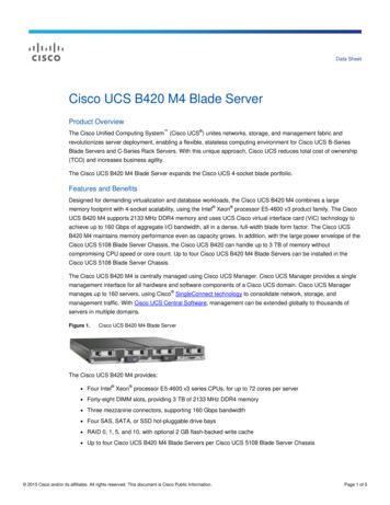
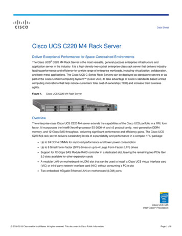
CH A P T E R1OverviewThis chapter provides an overview of the Cisco UCS C22 server features.This server is a part of the Cisco UCS C-Series rack-mount server family. It is a high-performance, 1RU(rack-unit) server. It is designed to operate in both standalone environments and as part of the CiscoUnified Computing System (UCS).The illustrations in this chapter show an overview of external server features. Internal server features areillustrated in Figure 3-4 on page 3-9.The server is orderable in two different versions, each with one of two different front panel/backplaneconfigurations: Cisco UCS C22 M3, small form-factor (SFF) drives, with 8-drive backplane. Holds up to eight 2.5-inch hard drives or solid state drives. Cisco UCS C22 M3, large form factor (LFF) drives, with 4-drive backplane). Holds up to four 3.5-inch hard drives.Figure 1-1 shows the front panel features of small form-factor drives version of the server.12Cisco UCS C22 Server (Small Form Factor Drives) Front Panel HDD08302158Figure 1-1101Power button/Power status LED 62Identification button/LED7Network link activity LED3System status LED8USB 2.0 ports (two)4Fan status LED9Pull-out asset tag5Temperature status LED10 Drives, hot-swappable (up to eight 2.5-inch drives)Power supply status LEDCisco UCS C22 Server Installation and Service GuideOL-26646-011-1
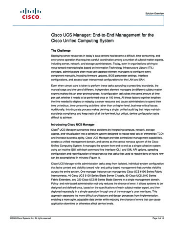
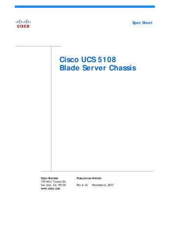
Chapter 1OverviewFigure 1-2 shows the front panel features of the large form-factor drives version of the server.Cisco UCS C22 Server (Large Form Factor Drives) Front Panel Features1532476HDD01HDD028HDD039285201Figure 1-2HDD04101Power button/Power status LED 62Identification button/LED7Network link activity LED3System status LED8USB 2.0 ports (two)4Fan status LED9Pull-out asset tag (serial number)5Temperature status LED10 Drives, hot-swappable (up to four 3.5-inch drives)Power supply status LEDCisco UCS C22 Server Installation and Service Guide1-2OL-26646-01
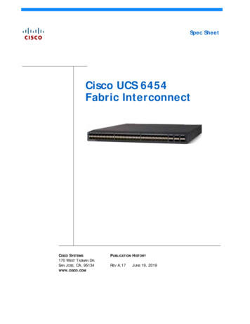
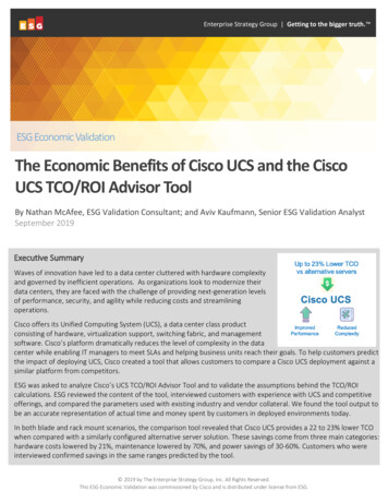
Chapter 1OverviewFigure 1-3 shows the rear panel features of the server (identical for both versions of the server).Figure 1-3Rear Panel Features123PCIe 2PCIe 1302159PSU 14567891Power supply6Serial port (DB-9 connector)2PCIe slot 2 on riser 2 (half-height, half-length, x8 lane)7VGA video port (DB-15 connector)3PCIe slot 1 on riser 1 (full-height, half-length, x16 lane, supports NCSI)810/100/1000 Base-T Ethernet dedicatedmanagement port4Dual 1-Gb Base-T Ethernet ports (two)9Rear Identification button/LED5USB 2.0 ports (four)–Table 1-1 lists the features of the server.Table 1-1Cisco UCS C22 Server FeaturesChassisOne rack-unit (1RU) chassis.ProcessorsOne or two Intel Xeon E5-2400 Series processors.MemoryThe server provides 12 DIMM1 sockets on the motherboard.NoteIn a single-CPU configuration, only 6 DIMM slots are active.BaseboardmanagementPilot III BMC, running Cisco Integrated Management Controller (CIMC) firmware.Network andmanagement I/OThe server provides these rear-panel connectors:Depending on your CIMC settings, the CIMC can be accessed through the 1-Gb Ethernet dedicated management port, the dual 1-Gb Ethernet LOM ports, or aCisco P81E virtual interface card.One 10/100/1000 Base-T Ethernet dedicated management portTwo 1-Gb Base-T Ethernet ports One RS-232 serial port One VGA2 video connector Four USB3 2.0 connectors There are also two USB 2.0 ports on the front panel.PowerOne 450 W power supply or one 650W power supply.See also Power Specifications, page A-2.CoolingFive fan modules for front-to-rear cooling.Cisco UCS C22 Server Installation and Service GuideOL-26646-011-3
Chapter 1Table 1-1OverviewCisco UCS C22 Server Features (continued)PCIe I/OTwo horizontal PCIe4 expansion slots on risers. See Replacing a PCIe Card, page 3-33 for slot specifications.In a single-CPU configuration, only PCIe slot 1 is active.NoteStorageInternal USBsupportDrives are installed into front-panel drive bays that provide hot-pluggable access.There are two versions of the server front panel and backplane: Small Form Factor drives—The server can hold up to eight 2.5 in. (63.5 mm)SAS5 or SATA6 hard drives or solid state drives. Large Form Factor—The server can hold up to four 3.5 in. (82.5 mm) SAS orSATA hard drives.The server has one internal USB 2.0 socket on the motherboard that you can use witha USB thumb drive for additional storage.The server can be ordered with an optional blank 8-GB Cisco USB Flash Drivepre-installed in the internal USB port.Cisco USB FlashDrive with pre-loadedutilitiesThis optional drive is pre-loaded with Cisco C-series Server utilities. This drivecontains four virtual drives. The four virtual drives contain, respectively: Cisco Server Configuration Utility Cisco Host Upgrade Utility Cisco C-Series server drivers set A blank virtual drive on which you can install an OS or a hypervisorSee Overview of the Pre-Loaded 16-GB Cisco USB Flash Drive, page 3-38 for moreinformation about enabling and booting the virtual drives.DiskManagement (RAID)For a list of RAID7 controller options and required cables, see RAID ControllerConsiderations, page C-1.RAID BackupThere is one mounting point inside the chassis that can be used for the SuperCappower module that can be used with an LSI MegaRAID-CV card.VideoMatrox G200e video controller. Resolution up to 1920 x1200, 16bpp at 60 Hz. Upto 256 MB of video memory.1. DIMM dual inline memory module2. VGA video graphics array3. USB universal serial bus4. PCIe peripheral component interconnect express5. SAS serial attached SCSI6. SATA serial advanced technology attachment7. RAID redundant array of independent disksCisco UCS C22 Server Installation and Service Guide1-4OL-26646-01
CH A P T E R2Installing the ServerThis chapter describes how to install the server, and it includes the following sections:NoteWarning Unpacking and Inspecting the Server, page 2-2 Preparing for Server Installation, page 2-3 Installing the Server In a Rack, page 2-5 Initial Server Setup, page 2-8 System BIOS and CIMC Firmware, page 2-12 Updating the BIOS and CIMC Firmware, page 2-12 Service Headers and Jumpers, page 2-14Before you install, operate, or service a server, review the Regulatory Compliance and SafetyInformation for Cisco UCS C-Series Servers for important safety information.IMPORTANT SAFETY INSTRUCTIONS This warning symbol means danger. You are in a situation that could cause bodily injury. Before youwork on any equipment, be aware of the hazards involved with electrical circuitry and be familiarwith standard practices for preventing accidents. Use the statement number provided at the end ofeach warning to locate its translation in the translated safety warnings that accompanied this device. Statement 1071SAVE THESE INSTRUCTIONSCisco UCS C22 Server Installation and Service GuideOL-26646-012-1
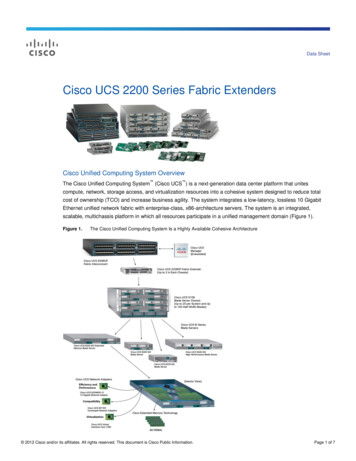
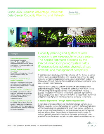
Chapter 2Installing the ServerUnpacking and Inspecting the ServerUnpacking and Inspecting the ServerCautionWhen handling internal server components, wear an ESD strap and handle modules by the carrier edgesonly.TipKeep the shipping container in case the server requires shipping in the future.NoteThe chassis is thoroughly inspected before shipment. If any damage occurred during transportation orany items are missing, contact your customer service representative immediately.To inspect the shipment, follow these steps:Step 1Remove the server from its cardboard container and save all packaging material.Step 2Compare the shipment to the equipment list provided by your customer service representative andFigure 2-1. Verify that you have all items.Step 3Check for damage and report any discrepancies or damage to your customer service representative. Havethe following information ready: Invoice number of shipper (see the packing slip) Model and serial number of the damaged unit Description of damage Effect of damage on the installationFigure 2-1Shipping Box 3UC302160S CCisc-S oeries1Server2Power cord3Documentation–Cisco UCS C22 Server Installation and Service Guide2-2OL-26646-01
Chapter 2Installing the ServerPreparing for Server InstallationPreparing for Server InstallationThis section provides information about preparing for server installation, and it includes the followingtopics: Installation Guidelines, page 2-3 Rack Requirements, page 2-4 Equipment Requirements, page 2-4 Slide Rail Adjustment Range, page 2-4Installation GuidelinesWarningTo prevent the system from overheating, do not operate it in an area that exceeds the maximumrecommended ambient temperature of: 40 C (104 F). Statement 1047WarningThe plug-socket combination must be accessible at all times, because it serves as the maindisconnecting device. Statement 1019WarningThis product relies on the building’s installation for short-circuit (overcurrent) protection. Ensure thatthe protective device is rated not greater than: 250 V, 15 A. Statement 1005WarningInstallation of the equipment must comply with local and national electrical codes. Statement 1074When you are installing a server, use the following guidelines:Caution Plan your site configuration and prepare the site before installing the server. See the Cisco UCS SitePreparation Guide for the recommended site planning tasks. Ensure that there is adequate space around the server to allow for servicing the server and foradequate airflow. The airflow in this server is from front to back. Ensure that the air-conditioning meets the thermal requirements listed in the Server Specifications. Ensure that the cabinet or rack meets the requirements listed in the “Rack Requirements” section onpage 2-4. Ensure that the site power meets the power requirements listed in the Server Specifications. Ifavailable, you can use an uninterruptible power supply (UPS) to protect agains
CCDE, CCENT, CCSI, Cisco Eos, Cisco Explorer, Cisco HealthPresence, Cisco IronPort, the Cisco logo, Cisco Nurse Connect, Cisco Pulse, Cisco SensorBase, . Cisco UCS C22 Server Installation and Service Guide OL-26646-01 Preface This preface describes the audience, organization, and conventions of the Cisco UCS C22 Server