Transcription
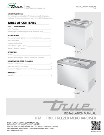
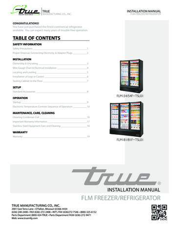
INSTALLATION MANUALflm freezer/refrigeratorTRUEmanufacturing co., inc.CONGRATULATIONS!You have just purchased the finest commercial refrigeratoravailable. You can expect many years of trouble-free operation.TABLE OF CONTENTSSAFETY INFORMATIONSafety Precautions1Proper Disposal, Connecting Electricity, & Adapter Plugs2INSTALLATIONOwnership & Uncrating3Wire Gauge Chart & Electrical Installation4Locating and Leveling5Installation of Legs or Castors6Sealing Cabinet to the Floor7SETUPStandard Accessories8FLM-54/54F TSL01OPERATIONStartup9Electronic Temperature Controls Sequence of Operation10MAINTENANCE, CARE, CLEANINGCleaning Condenser Coil16Important Warranty Information17Stainless Steel Equipment Care and Cleaning18WARRANTYWarranty19FLM-81/81F TSL01INSTALLATION MANUALFLM FREEZER/REFRIGERATORTRUE MANUFACTURING CO., INC.2001 East Terra Lane O’Fallon, Missouri 63366-4434(636)-240-2400 FAX (636)-272-2408 INT'L FAX (636)272-7546 (800)-325-6152Parts Department (800)-424-TRUE Parts Department FAX# (636)-272-9471Web: www.truemfg.com
TRUEwww.truemfg.comfull length merchandisersNOTICE TO CUSTOMERLoss or spoilage of products in your refrigerator/freezer is not covered by warranty. In addition tofollowing recommended installation proceduresyou must run the refrigerator/freezer 24 hoursprior to usage.SAFETY INFORMATIONHow to Maintain Your True Refrigerator to Receive the Most Efficient and Successful Operation.You have selected one of the finest commercial refrigeration units made. It is manufactured under strict quality controls with only the bestquality materials available. Your TRUE cooler when properly maintained will give you many years of trouble-free service.WARNING: Use this appliance for its intended purpose as described in this Owner Manual.TO LOCATE REFRIGERANT TYPE, SEE SERIAL LABEL INSIDE CABINET. This cabinet may contain fluorinated greenhousegas covered by the Kyoto Protocol (please refer to cabinet’s inner label for type and volume, GWP of 134a 1,300. R404a 3,800).FOR HYDROCARBON REFRIGERATION ONLY (R-290) SEE BELOW: DANGER - Risk of fire or explosion. Flammable refrigerant used. Do not use mechanical devices to defrost refrigerator. Do notpuncture refrigerant tubing. DANGER - Risk of fire or explosion. Flammable refrigerant used. To be repaired only by trained service personnel. Do not puncturerefrigerant tubing. CAUTION - Risk of fire or explosion. Flammable refrigerant used. Consult repair manual/owner’s guide before attempting to servicethis product. All safety precautions must be followed. CAUTION - Risk of fire or explosion. Dispose of properly in accordance with federal or local regulations. Flammable refrigerant used. CAUTION - Risk of fire or explosion due to puncture of refrigerant tubing; follow handling instructions carefully. Flammable refrigerantused. CAUTION - Keep clear of obstruction all ventilation openings in the appliance enclosure or in the structure for building-in.SAFETY PRECAUTIONSWhen using electrical appliances, basic safety precautions should befollowed, including the following: This refrigerator must be properly installed and located inaccordance with the Installation Instructions before it is used. Do not allow children to climb, stand or hang on the shelvesin the refrigerator. They could damage the refrigerator andseriously injure themselves. Do not touch the cold surfaces in the freezer compartmentwhen hands are damp or wet. Skin may stick to theseextremely cold surfaces. Do not store or use gasoline or other flammable vapors andliquids in the vicinity of this or any other appliance. Do not storeexplosive substances such as aerosol cans with a flammablepropellant in this appliance.1 Keep fingers out of the “pinch point” areas; clearances betweenthe doors and between the doors and cabinet are necessarilysmall; be careful closing doors when children are in the area.Unplug the refrigerator before cleaning and making repairs.Setting temperature controls to the 0 position does notremove power to the light circuit, perimeter heaters, orevaporator fans.NOTE: We strongly recommend that any servicing be preformedby a qualified technician.
TRUEwww.truemfg.comfull length merchandisersDANGER!RISK OF CHILDENTRAPMENTPROPER DISPOSAL OF THE REFRIGERATORChild entrapment and suffocation are not problems of the past.Junked or abandoned refrigerators are still dangerous even if theywill sit for “just a few days.” If you are getting rid of your old refrigerator, please follow the instructions below to help prevent accidents.BEFORE YOU THROW AWAY YOUR OLDREFRIGERATOR OR FREEZER: Take off the doors. Leave the shelves in place so that children may not easily climbinside.APPLIANCE DISPOSALWhen recycling appliance please make sure that the refrigerants arehandled according to local and national codes, requirements andregulations.REFRIGERANT DISPOSALYour old refrigerator may have a cooling system that uses “OzoneDepleting” chemicals. If you are throwing away your old refrigerator,make sure the refrigerant is removed for proper disposal by a qualified service technician. If you intentionally release any refrigerants youcan be subject to fines and imprisonment under provisions of theenvironmental regulations.USE OF EXTENSION CORDSWARNING!HOW TO CONNECT ELECTRICITYDO NOT, UNDER ANY CIRCUMSTANCES, CUT ORREMOVE THE GROUND PRONG FROM THE POWERCORD. FOR PERSONAL SAFETY, THIS APPLIANCEMUST BE PROPERLY GROUNDED.The power cord from this appliance is equipped with a groundingplug which minimizes the possibility of electric shock hazard.Have the wall outlet and circuit checked by a qualified electrician tomake sure the outlet is properly grounded.If the outlet is a standard 2-prong outlet, it is your personal responsibility and obligation to have it replaced with the properly groundedwall outlet.The refrigerator should always be plugged into it’s own individualelectrical circuit, which has a voltage rating that matches the ratingplate.This provides the best performance and also prevents overloadingbuilding wiring circuits which could cause a fire hazard from overheated wires.Never unplug your refrigerator by pulling on the power cord. Alwaysgrip plug firmly and pull straight out from the outlet.Repair or replace immediately all power cords that have becomefrayed or otherwise damaged. Do not use a cord that shows cracksor abrasion damage along its length or at either end.When removing the refrigerator away from the wall, be careful notto roll over or damage the power cord.If supply power cord is damaged it should be replaced with originalequipment manufacture parts. To avoid hazard this should be doneby a qualified service technician.NEVER USE AN EXTENSION CORD! TRUE will not warranty any refrigerator that has been connected to an extension cord.USE OF ADAPTER PLUGSREPLACEMENT PARTSNEVER USE AN ADAPTER PLUG! Because of potential safetyhazards under certain conditions, we strongly recommend against theuse of an adapter plug. Component parts shall be replaced with like components. Servicing shall be done by authorized service personnel, tominimize the risk of possible ignition due to incorrect parts orimproper service. Lamps must be replaced by identical lamps only. If the supply cord is damaged, it must be replaced by a specialcord or assembly available from the manufacturer or its serviceagent.The incoming power source to the cabinet including any adaptersused must have the adequate power available and must be properlygrounded. Only adapters listed with UL should be used.NORTH AMERICA USE ONLY!NEMA plugsTRUE uses these types of plugs. If you do not have the right outlethave a certified electrician install the correct power source.NOTE: International plug configurations vary by voltage and 115/60/1NEMA-5-20R208-230/60/1NEMA-6-15R2
TRUEwww.truemfg.comfull length merchandisersINSTALLATIONOWNERSHIPTo ensure that your unit works properly from the first day, it mustbe installed properly. We highly recommend a trained refrigerationmechanic and electrician install your TRUE equipment. The cost of aprofessional installation is money well spent.Before you start to install your TRUE unit, carefully inspect it forfreight damage. If damage is discovered, immediately file a claim withthe delivery freight carrier.TRUE is not responsible for damage incurred during shipment.UNCRATINGTOOLS REQUIRED Adjustable Wrench Phillips Screwdriver LevelThe following procedure is recommended for uncrating the unit:A. Remove the outer packaging, (cardboard and bubbles orstyrofoam corners and clear plastic). Inspect for concealeddamage. Again, immediately file a claim with the freight carrierif there is damage.B.Move your unit as close to the final location as possible beforeremoving the wooden skid.C. Remove door bracket on swinging glass door models (seeimage 1-2). Do not throw the bracket or blocks away. Forfuture cabinet movement the bracket and blocks will need tobe installed so the glass door does not receive any damage.(See image for bracket and shipping block removal)NOTE: KEYS FOR COOLERS WITH DOOR LOCKSARE LOCATED IN WARRANTY PACKETS.132ELECTRIC INSTALLATION & SAFETYINFORMATION If the supply cord is damaged, it must be replaced by a specialcord or assembly available from the manufacturer or its serviceagent. Lamps must be replaced by identical lamps only. Appliance tested according to the climate classes 5 and 7temperature and relative humidity.ELECTRICAL INSTRUCTIONSA. Before your new unit is connected to a power supply, check theincoming voltage with a voltmeter. If anything less than 100% ofthe rated voltage for operation is noted, correct immediately.B. All units are equipped with a service cord, and must bepowered at proper operating voltage at all times. Refer tocabinet data plate for this voltage.TRUE RECOMMENDS THAT A SOLE USE CIRCUIT BEDEDICATED FOR THE UNIT.WARNING: Compressor warranties are void if compressor burnsout due to low voltage.WARNING: Power supply cord ground should not be removed!WARNING: Do not use electrical appliances inside the food storage compartments of the appliances unless they are of the typerecommended by the manufacturer.NOTE: To reference wiring diagram, remove front louvered grill,wiring diagram is positioned on the inside cabinet wall.
TRUEwww.truemfg.comfull length merchandisersWIRE GAUGE CHART115 VoltsAmps23456Distance In Feet To Center of Load20 30 40 50 60 70 80 90 100 120 140 888668666666665665546554465443544334433243221230 VoltsAmps56789Distance In Feet To Center of Load20 30 40 50 60 70 80 90 100 120 140 22114
TRUEwww.truemfg.comfull length merchandisersLOCATINGLEVELINGA. Remove louver from the front of cabinet (see page 19 forlouver grill removal / reinstallation) and backguard (if applicable)from rear of cabinet.A. Set unit in its final location. Be sure there is adequate ventilationin your room. Under extreme heat conditions, (100 F ,38 C ), you may want to install an exhaust fan.B.Skid bolts are located in each of 4 corners inside cabinetbottom. (See photo A).C. Remove skid bolts. (See photo B).WARNING: WARRANTY IS VOID IF VENTILATION ISINSUFFICIENT.D. Cut straps if applicable. (See photo C).E.Carefully lift cabinet off of skid.F.Appliance tested according to the climate classes 5 and 7 fortemperature and relative humidity.B.Proper leveling of your TRUE cooler is critical to operatingsuccess (for non-mobile models). Effective condensate removaland door operation will be effected by leveling.C. The cooler should be leveled front to back and side to side witha level.D. Ensure that the drain hose or hoses are positioned in the pan.ARemoving skid frombottom of cabinet.E.Free plug and cord from inside the lower rear of the cooler(do not plug in).F.The unit should be placed close enough to the electrical supplyso that extension cords are never used.WARNING: CABINET WARRANTIES ARE VOIDIF OEM POWER CORD IS TAMPERED WITH. TRUEWILL NOT WARRANTY ANY UNITS THAT ARECONNECTED TO AN EXTENSION CORD.PCNOTEWhen moving cabinet DO NOT pushon door hinges.51227-5REMOVE COVER MAKE POWER CONNECTIONNEPCO/CENTRALABB
TRUEwww.truemfg.comfull length merchandisersINSTALLATION OF CASTORS OROPTIONAL LEGSImportant Safeguard for installation of leg/castor. Images 1-5 demonstrate procedure.SECURING CASTORS AND LEGSTo obtain maximum strength and stability of the unit, it is importantthat you make sure each castor is secure. Optional legs are handtightened securely against the lower rail assembly see image 4-5. Thebearing race on the castor or the top edge of the leg must make firmcontact with the rail.12Thread castor into the underside ofcabinet frame rail.For leveling, insert the shim betweencastor and frame rail.LEVELING SHIMSFour leveling shims have been provided for leveling castored unitspositioned on uneven floors. Shims must be positioned between railend and bearing race.A. Turn the bearing race counter-clockwise until the cabinet islevel. Level front to back and side to side. (diagonally)B.Install the desired number of shims, making sure the slot of theshim is in contact with the threaded stem of the castor. Seeimage 2.C. If more than one shim is used, turn the slot at a 90 angle sothey are not in line.34Use the tool provided to tighten thecastor into place.Thread leg into cabinet bottomframe rail.D. Turn the bearing race clockwise to tighten and secure thecastor by tightening the anchoring bolt with a 3/4 inch openend wrench or the tool provided. See image 3.CAUTION: TO AVOID DAMAGE TO LOWER RAILASSEMBLY, SLOWLY RAISE UNIT TO UPRIGHTPOSITION.NOTE: OPEN HOLES LOCATED ON THE CROSSMEMBERS OF THE FRAME RAIL SHOULD BEPLUGGED BEFORE UNIT IS IN USE.5The end of the leg is adjustable foreasy leveling.Lower RailAssemblyLower Rail AssemblyRail EndSnug FitHereRail EndBearingRaceSnug FitHereLeveling ShimLegCastor6
TRUEwww.truemfg.comfull length merchandisersSEALING CABINET TO FLOORSTEP 6 - Raise and block the rear of the cabinetSTEP 1 - Position Cabinet - Allow one inch between the wall andrear of the GDM refrigerator to assure proper ventilation. For GDMfreezers 3 inches between the wall and rear of the cabinet will assureproper ventilation.STEP 7 - Apply sealant on floor as outlined in Step 5 on otherthree sides.STEP 2 - Level Cabinet - Cabinet should be level, side to side andfront to back. Place a carpenter’s level in the interior floor in fourplaces:A. Position level in the inside floor of the unit near the doors.(Level should be parallel to cabinet front). Level cabinet.B.Position level at the inside rear of cabinet. (Again level shouldbe placed parallel to cabinet back).C. Perform similar procedures to steps A & B by placing the levelon inside floor (left and right sides - parallel to the depth of thecooler). Level cabinet.STEP 8 - Examine to see that cabinet is sealed to floor aroundentire perimeter.NOTE: Asphalt floors are very susceptible to chemical attack. Alayer of tape on the floor prior to applying the sealant will protectthe floor.NSF APPROVED SEALANTS:1. Minnesota Mining #ECU800 Caulk2. Minnesota Mining #ECU2185 Caulk3. Minnesota Mining #ECU1055 Bead4. Minnesota Mining #ECU1202 BeadSTEP 3 - Draw an outline on the base on the floor.5. Armstrong Cork - Rubber CaulkSTEP 4 - Raise and block the front side of the cabinet.6. Products Research Co. #5000 Rubber CaulkSTEP 5 - Apply a bead of “NSF Approved Sealant”, (see list below),to floor on half inch inside the outline drawn. The bead must be heavyenough to seal the entire cabinet surface when it is down on thesealant.7. G.E. Silicone Sealer78. Dow Corning Silicone Sealer
TRUEfull length merchandiserswww.truemfg.comSETUPSTANDARD ACCESSORIESSHELVING INSTALLATION / OPERATIONSHELF INSTALLATION:NOTE: Doors are manufactured with a 90 stay open feature toassist with loading and unloading of the cabinet.CANTILEVER SHELVING INSTALLATION:Note: For ease of installation it is recommended to install thelower shelf first.Cantilever ShelfBracket Support TabAngle Adjustment TabsINSTALLING SHELF BRACKET INTOSHELF STANDARDSTEP 1Position the shelf brackets in front of the shelf standard. Raise thefront of the bracket up at a 45 degree angle to allow the bracketsupport tab to slide in and up into the shelf standard. See image 1.Shelf StandardSTEP 2Slide the shelf angle adjustment tabs into the shelfstandard. Position notch in bracket to support shelfat desired angle.8
TRUEfull length merchandiserswww.truemfg.comOPERATIONSTARTUPA. The compressor is ready to operate. Plug in the cooler.B.Temperature controls are factory-set to give refrigeratorsan approximate temperature of 35 F (1.7 C) and freezersan approximate temperature of -10 F (-23.3 C). Allow unitto function several hours, completely cooling cabinet beforechanging the control setting. E lectronic control with display:- Behind bottom louvered grillUSAGE: This Type II display equipment is intended for use in an areawhere the environmental conditions are controlled and maintainedso that the ambient temperature typically does not exceed 80ºF(27ºC).See website for adjustments, sequence of operation, and moreinformation.LIGHT SWITCH LOCATION: FLM models will have the lightswitch located on the left side of the ceiling inside the unit.Temperature Control Location and Settings.C. Excessive tampering with the control could lead to servicedifficulties. Should it ever become necessary to replacetemperature control, be sure it is ordered from your TRUEdealer or recommended service agent.D. Good air flow in your TRUE unit is critical. Be careful toload product so that it neither presses against the back wall,nor comes within four inches of the evaporator housing.Refrigerated air off the coil must circulate down the back wall.NOTE: If the unit is disconnected or shut off, wait five minutesbefore starting again.9RECOMMENDATION - Before loading product we recommendyou run your TRUE unit empty for two to three days. This allows youto be sure electrical wiring and installation are correct and no shipping damage has occurred. Remember, our factory warranty does notcover product loss!
TRUEfull length merchandiserswww.truemfg.comELECTRONIC TEMPERATURE CONTROLSLAE ELECTRONIC TEMPERATURE CONTROL GENERAL SEQUENCE OF OPERATIONt1 Thermostatt2 Defrostt3 Displayt3 probe is not installed and / or activated in all applicationswhen t3 is not installed and / or activated, the display probe is t1.LAE ELECTRONIC CONTROL GENERAL SEQUENCE OF OPERATION1. Cabinet is plugged in.a. Display will illuminate.b. Interior light will illuminate on Glass Door Models only. Solid door cabinet lights are controlled by the door switch.2. After the LAE control preprogrammed time delay of up to 6 minutes, the compressor and evaporator fan(s) will start if thecontrol is calling for cooling.a. Control or condenser fans may be already pre-programmed from the factory so at the start of every compressor cycle orduring a defrost cycle, the condenser fan(s) will reverse for 30 seconds to blow dirt off the condensing coil.3. The LAE control will cycle the compressor but may also cycle evaporator fan(s) on and off determined by the Set-Point andDifferential temperatures.a. The Set-Point is the adjustable preprogrammed temperature.b. The Differential is the non adjustable preprogrammed temperature.c. The LAE control is designed to read and display a cabinet temperature not a product temperature.This cabinet temperature may reflect the refrigeration cycle of the Set-Point and its Differential, or it may show anaverage temperature.The most accurate temperature on a cabinets operation is to verify the product temperature.4. The LAE control may be preprogrammed to initiate defrost by interval or at specific times of day.a. At this time the “dEF” will appear on the display and compressor will turn off until a preprogrammed temperature orduration is reached. During this time for freezers only, evaporator fan(s) will also turn off and the coil heater and drain tubeheaters will also be energized. Some cabinets may also change the rotation of the reversing condenser fan motor.b. After the preprogrammed temperature or duration for defrost has been reached there may be a short delay for both thecompressor and evaporator fans to restart. At this time “dEF” may still appear on the display for a short time.10
TRUEwww.truemfg.comfull length merchandisersHOW TO DIAGNOSE AN LAE ELECTRONIC CONTROLIndicator lights for Refrigeration/Heating Mode, Fan Operation, Defrost Mode.LAE ControlLAE Control IconsCompressor RunningEvaporator Fan RunningCabinet in DefrostActivation of 2nd Parameter SetAlarmInfo / Set PointButtonManual Defrost /Down ButtonManual ActivationUp ButtonStand-ByButtonUSING THE LAE ELECTRONIC CONTROLLOCKING AND UNLOCKING THE LAE CONTROLLER:1WHY: Locking of control is necessary to prevent changes to program that may affectcabinet operation.2HOW TO LOCK AND UNLOCK LAE CONTROLLER:STEP 1 - To change lock setting press and release the Info button“t1” will appear. See image 1.STEP 2 - Press the Down button.until “Loc” appears. See image 2.STEP 3 - While pressing and holding the Info buttonpress the Upor Downbutton to change the lock settings. If “no” appears,the controller is unlocked. If “yes” appears, the controller is locked. Seeimages 3 and 4.STEP 4 - Once the lock setting has been set correctly release theinfo button. Wait 5 seconds for the display to show temperature.See image 5.3Image 3: If “no” appears on screen,the controller is unlocked.4Image 4: If “yes” appears on screen, thecontroller is locked.511
TRUEwww.truemfg.comfull length merchandisersLAE ControlInfo / Set PointButtonManual Defrost /Down ButtonManual ActivationUp ButtonStand-ByButtonHOW TO TURN OFF THE LAE ELECTRONIC CONTROL:May need to unlock control.WHY: Turning off the control will deactivate all electrical components.CAUTION: Turning off the control will not shut off power to the cabinet. Cabinetmust be unplugged prior to any repair.1HOW TO TURN OFF THE LAE ELECTRONIC CONTROL:STEP 1 - To turn off control, press and hold the Stand-by button"OFF" appears. Release Stand-by button. See Image 2.until2STEP 2 - To turn on control, repeat prior steps and a temperature will appear.12
TRUEwww.truemfg.comfull length merchandisersLAE ControlInfo / Set PointButtonManual Defrost /Down ButtonManual ActivationUp ButtonStand-ByButtonCHANGING THE "SET POINT":May need to unlock control.WHY: To increase or decrease product / cabinet temperature.NOTE: The most accurate temperature of a cabinet's operation can be verified by theproduct temperature.1HOW TO CHANGE THE “SET POINT”:STEP 1 - To see the set point, press and hold the Info buttonSee image 1.STEP 2 - While still holding the Info buttonDownbutton to change the “set point”., press the Up.orSTEP 3 - Once the “set point” has been set correctly release the Infobutton. The display will show temperature. See image 2.132
TRUEwww.truemfg.comfull length merchandisersLAE ControlInfo / Set PointButtonManual Defrost /Down ButtonManual ActivationUp ButtonStand-ByButtonINITIATE A MANUAL DEFROST:May need to unlock control.WHY: A one time additional defrost may be necessary to clear accumulated frost / ice from evaporator coil.HOW TO INITIATE A MANUAL DEFROST:The method to initiate a manual defrost is determined by the Defrost Mode Parameter “DTM” preprogrammed in the controller.REGULAR TIME DEFROST (TIM)If controller is preprogrammed for “TIM”, press and release the Manual Defrost buttonuntil “dEF” appears.NOTE: Defrost will only terminate once a specific preset temperature or a preset time duration is reached.14
TRUEwww.truemfg.comfull length merchandisersLAE ControlHOW TO CHANGE DISPLAY READOUT FROMFAHRENHEIT TO CELSIUS:Info / Set PointButtonManual Defrost /Down ButtonManual ActivationUp ButtonStand-ByButton1aMay need to unlock control.This can NOT be changed with the LAE model AR2-28 version of the control. Seepage 32 for more information.WHY: Changing readout will assist with customer application.1bHOW TO CHANGE DISPLAY READOUT FROMFAHRENHEIT TO CELSIUS:STEP 1 - To change the display, press and hold the Info buttonandthe Stand-by buttonat the same time. “MdL” or “SPL” will appear.See images 1a and 1b.STEP 2 - Push the Down buttonSTEP 3 - Press and hold the Info buttonSee image 3.2until “ScL” appears. See image 2.to see the “readout scale”.3STEP 4 - While pressing and holding the Info button, press theupor downbutton to change the “readout scale".See image 4.STEP 5 - Once the “readout scale” has been changed, release the infobutton.4STEP 6 - Wait 30 seconds for the display to show temperature.See image 5.515
TRUEwww.truemfg.comfull length merchandisersMAINTENANCE, CARE, CLEANINGCLEANING THE CONDENSER COILWhen using electrical appliances, basic safety precautions should befollowed, including the following:TOOLS REQUIRED Phillips Screwdriver Air Tank or CO2 Tank Stiff Bristle Brush Vacuum Cleaner Adjustable WrenchSTEP 1 - Disconnect power to unit.STEP 2SWING DOOR MODELS: (See Image 2)Take off lower grill assembly by opening the door and removing screws from the top of the louver grill. Some models havea door light switch. Please use caution when removing the grillon these models. Do not pinch wires. For reinstall, reattach thegrill to the magnets on front of the cabinet and reinstall thescrews on top of the grill.STEP 3 - Remove bolts anchoring compressor assembly to framerails and carefully slide out. (tube connections are flexible)STEP 4 - Clean off accumulated dirt from condensing coil with astiff bristle brush.STEP 5 - Lift cardboard cover above fan at plastic plugs and carefullyclean condenser coil and fan blades.STEP 6 - After brushing condenser coil vacuum dirt from coil, andinterior floor.STEP 7 - Replace cardboard cover. Carefully slide compressorassembly back into position and replace bolts.STEP 8 - Reinstall louver assembly onto unit with appropriate fasteners and clips. Tighten all screws.STEP 9 - Connect unit to power and check to see if condenser isrunning.216
TRUEwww.truemfg.comfull length merchandisersIMPORTANT WARRANTY INFORMATIONCondensers accumulate dirt and require cleaning every 30 days.Dirty condensers result in compressor failure, product loss, and lostsales, which are not covered by warranty.If you keep the Condenser clean you will minimize your serviceexpense and lower your electrical costs. The Condenser requiresscheduled cleaning every thirty days or as needed.Air is pulled through the Condenser continuously, along with dust,lint, grease, etc.A dirty Condenser can result in NON-WARRANTEED part &Compressor Failures, Product Loss, and Lost Sales.Proper cleaning involves removing dust from the Condenser. By usinga soft brush, or vacuuming the Condenser with a shop vac, or usingCO2, nitrogen, or pressurized air.THE CLEANING OF THE CONDENSER IS NOTCOVERED BY THE WARRANTY!HOW TO CLEAN THE CONDENSER:1.Disconnect the electricalpower to the unit.2.Remove the louveredgrill.3.Vacuum or brush the dirt,lint, or debris from thefinned condenser coil.4.AirflowCondensing UnitCondenserIf you have a significant dirt build up you can blow out thecondenser with compressed air.(CAUTION MUST BE USED TO AVOID EYE INJURY.EYE PROTECTION IS RECOMMENDED.)If you cannot remove the dirt adequately, please call your refrigeration service company.5.When finished be sure to replace the louvered grill. The grillprotects the condenser.On most of the reach-in units the condenser is accessible in therear of the unit. You must remove the cabinet grill to expose theCondenser.6.Reconnect the electrical power to the unit.The Condenser looks like a group of vertical fins. You need to be ableto see through the condenser for the unit to function at maximumcapacity. Do not place filter material in front of condensing coil. Thismaterial blocks air-flow to the coil similar to having a dirty coil.17If you have any questions, please call TRUE Manufacturing at 636240-2400 or 800-325-6152 and ask for the Service Department.Direct to Service Department 1(855)372-1368. Service DepartmentAvailability Monday-Thursday 7:00 a.m. to 7:00 p.m., Friday 7:00 a.m.to 6:00 p.m. and Saturday 8:00 a.m. to 12:00 p.m. CST.
TRUEwww.truemfg.comfull length merchandisersSTAINLESS STEEL EQUIPMENT CAREAND CLEANING8 STEPS THAT CAN HELP PREVENT RUST ONSTAINLESS STEEL:CAUTION: Do not use any steel wool, abrasive or chlorine basedproducts to clean stainless steel surfaces.1.USING THE CORRECT CLEANING TOOLSUse non-abrasive tools when cleaning your stainless steelproducts. The stainless steel’s passive layer will not be harmedby soft cloths and plastic scouring pads. Step 2 tells you how tofind the polishing marks.2.CLEANING ALONG THE POLISH LINESPolishing lines or “grain” are visible on some stainless steels.Always scrub parallel to visible lines on some stainless steels.Use a plastic scouring pad or soft cloth when you cannot seethe grain.3.USE ALKALINE, ALKALINE CHLORINATED ORNON-CHLORIDE CONTAINING CLEANERSWhile many traditional cleaners are loaded with chlorides, theindustry is providing an ever increasing choice of non-chloridecleaners. If you are not sure of your cleaner’s chloride contentcontact your cl
TRUE MANUFACTURING CO., INC. 2001 East Terra Lane O'Fallon, Missouri 63366-4434 (636)-240-2400 FAX (636)-272-2408 INT'L FAX (636)272-7546 (800)-325-6152 . Use this appliance for its intended purpose as described in this Owner Manual. How to Maintain Your True Refrigerator to Receive the Most Efficient and Successful .