Transcription
DUKANEIntelligent Assembly SolutionsAPPLICATION NOTEAN504Ultrasonic Acoustic Stack Mounting GuidelinesCorrect acoustic stack mounting is vital to process consistency and equipment life.1) The ultrasonic stack should be supported in two locations. The two supports should be machined together orconnected by a common plate which is rigid and prevents deflection, torsion and bending of the stack. A minimumof 0.5” (13mm) thick aluminum or steel plate should be used.2) The bores of the two supports must be concentric within 0.005” (.1mm) and must allow for a clearance of0.003”-0.010” oversize with respect to the booster/ horn and transducer clamping ring diameters. This insures thatthere is no bending or excessive compression force applied to the booster/horn rings and transducer housing.3) The booster/horn support should be designed with upper and lower ridges to prevent the ultrasonic stack fromfalling out of the support and to provide a thrust surface for axial forces. The support ridge should be0.100”-0.150” (2.5mm) wide and should allow at least 0.005” (0.1mm) axial clearance to prevent the booster/hornclamp ring from binding in the support and to make installing and removing the ultrasonic stack easier.4) The support design should incorporate slots or other mounting provisions which allow for variation in stackcomponent lengths. Boosters and horns can vary up to 0.5” (13mm) due to material properties. This may requirean adjustment to the height of the stack above the product.5) Supports which use split clamps are preferred for easy setup and adjustment. A minimum of 0.025” (1mm) gapshould be maintained between the upper and lower sections of a split clamp. Inadequate or excessive clampingforce can cause premature equipment failure and/or noisy operation. The bolt torque spec is 15 ft-lb (20 N-m) fora 1/4-20 screw (6mm).6) Supports and other machinery must be designed so that there is no contact with the horn or booster except indesignated clamping areas as per the guidelines in this document. Any other horn, booster or transducer contactcould result in premature equipment failure and/or noisy operation.7) Machinery should be designed to allow for free ultrasonic cable movement without binding. The minimum cablebending radius is 2.5” (65mm).8) Machinery should be designed so that the cutting or welding forces are axial to the centerline of the ultrasonicstack and parallel to the face of the sonitrode / horn. Offset or side loading can cause equipment failure and/ornoisy operation. Typically, 1 to 3 CFM of air flow is required to achieve adequate cooling but an exact value isapplication dependent.9) Proper acoustic stack assembly is critical. The ultrasonic booster end which must be attached to the ultrasonichorn is marked on the booster. Refer to the Dukane white paper for more detailed information on assembling andmaintaining the ultrasonic stack.10) Clean dry air for cooling must be provided to the ultrasonic stack assembly including the transducer. Cooling airmust be filtered (5u or better) to 5 microns. No electrically conductive media or condensing water vapor ispermitted inside the transducer housing. Additional cooling should be provided to the booster and horn to preventany part of the ultrasonic stack assembly from exceeding 110Fº (43ºC). Exhaust air from the transducer may beutilized to cool other portions of the ultrasonic stack. (See bullet “I” on inside).11) Dukane “S” series transducers are rated for IP65. Additional low pressure washdown is permitted but submersionand high pressure washdown may compromise the transducer seals. Consult factory for higher ratings on a caseby case basis. Dukane components are made from anodized aluminum, stainless steel and titanium with Vitonand Neoprene seals. Material compatibility with cleaning solutions should be verified before putting equipmentinto service.12) To conform with UL 61010-1 and CAN/CSA-22.2, the empty space between the receptacle and plug inside all 3pin MIL-SPEC connectors shown in image (see call out M) must be filled with Dow Corning #4 electrical insulatingcompound. This does not apply to other connector types.AN504 (REV 03) Dukane IAS, LLC 2016. All Rights Reserved.
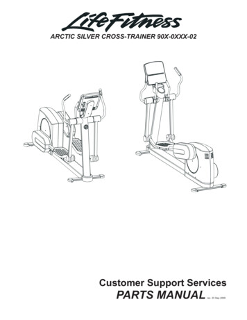
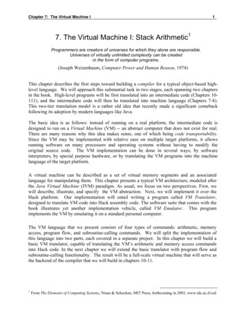
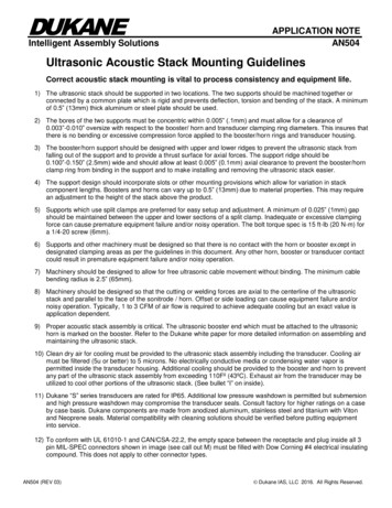
DUKANEIntelligent Assembly SolutionsAPPLICATION NOTEAN504Dukane Open Probe Mount EX-8331-00A. Common mounting plate to ensure concentricity betweenconverter, booster and horn flat /- 0.0005” (0.013mm).B. Slotted mounting holes on common back plate toaccommodate changes in horn and booster lengths.C. Mount designed with undercuts to take up load fromprocess on booster clamp ring surfaces.G. Air cooling input, sufficient to prevent acoustic stack(horn/sonotrode, booster, converter) from exceeding110ºF (43ºC). (Application/process dependent)H. Cable placement to eliminate strain or sharp bends.I. Exhaust air may be plumbed to provide additional cooling toconverter output end and horn (See Figure A, Page 4.)D. No deflection permitted. Mount should prevent stress anddeflection on booster converter interface due tomisalignment.J. Nothing to come in contact with transducer output, boosterbody or sonotrode/horn. Do not attach to, or modify thesecomponents.E. Mount must maintain correct bore tolerances for boosterclamp ring and probe. 0.005” – 0.000”(0.127mm -0 .000mm). Bores to be concentric. /- 0.005” (0.127mm).K. Ensure proper orientation of booster, output end tosonotrode/horn.F. Inadequate or excessive clamping force on the thesecomponents can cause premature equipment and processfailures. Bolt clamp torque specification is 15 lb.ft (20 Nm)4 places.L. Load to be centered and parallel to face of sonitrode/horn.Minimize side load of acoustic stack.M. Reference guideline 12 on the previous page for electricalinsulation requirements.Proper acoustic stack assembly is criticalPlease see:Ultrasonic Probes/Stacks-Understanding and Caringfor the Heart of your Ultrasonic Systemhttp://www.dukane.com/us/SE Stackarticle.htmAN504 (REV 03) Dukane IAS, LLC 2016. All Rights Reserved.
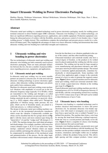
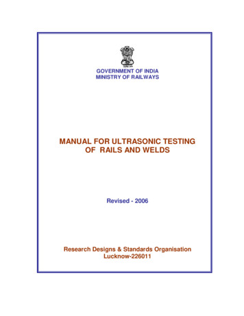
DUKANEIntelligent Assembly SolutionsAPPLICATION NOTEAN504Dukane Open Probe Mount EX-8331-00AN504 (REV 03) Dukane IAS, LLC 2016. All Rights Reserved.
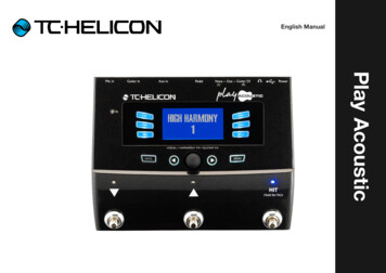
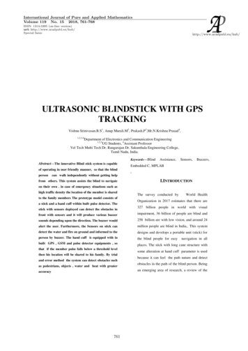
DUKANEIntelligent Assembly SolutionsAPPLICATION NOTEAN504Ultrasonic Acoustic Stack Mounting DrawingsEX-8331-00 standard probe mounts shown withDukane 41S30 sealed 20 kHz stainless steelIP65 rated converter and titanium boosterAN504 (REV 03) Dukane IAS, LLC 2016. All Rights Reserved.
DUKANEIntelligent Assembly SolutionsAPPLICATION NOTEAN504Troubleshooting TipsProblem - excess noise or system overload.1. Ensure proper cooling is in place.2. Inspect complete acoustic stack for over temperature. Components that have experienced excessive heat may bepermanently damaged, consult factory before putting units back in production.3. Remove acoustic stack from mount. Inspect for missing components; inspect for nicks, cracks, scrapes orevidence of metal to metal contact.4. Inspect mount to ensure proper clamp torque and tolerances.5. Disassemble and re-assemble acoustic stack following proper procedures. See, Ultrasonic Probes/Stacks Understanding and caring for the heart of your ultrasonic system white des/Ultrasonic Probes.pdf6. If problem still exists, contact the manufacturer.Visit http://www.dukane.com/us/DL DrawingsLayout.asp for downloadable drawings PDF, DWG, DXF & STP.20 kHz Standard Mount EX-8331-0020 kHz Narrow Mount EX-8468-0030/40 kHz Standard Mount EX-8471-0015 kHz Standard Mount EX-8470-00Available in anodized aluminum or stainless steelNote: All specifications are subject to change without notice. Please consult Dukane IAS, LLC for any updated information.AN504 (REV 03) Dukane IAS, LLC 2016. All Rights Reserved.
DUKANEIntelligent Assembly SolutionsAPPLICATION NOTEAN504Dukane IAS, LLCIntelligent Assembly Solutions2900 Dukane DriveSt. Charles, IL 60174 USATel: (630) 797-4900Fax: (630) 797-4949http://www.dukane.com/usDisclaimer: Dukane IAS, LLC assumes no responsibility for any errors which may appear in this document, reserves the right to change devices orspecifications detailed herein at any time without notice, and does not make any commitment to update the information contained herein.AN504 (REV 03) Dukane IAS, LLC 2016. All Rights Reserved.
DUKANEIntelligent Assembly SolutionsAPPLICATION NOTEAN504DOCUMENT INFO:DATE: 06/06/2016ECN:DRAWN: DSSCHECKED:APPROVED:ENGINEER:REVISION INFO:ISSDESCRIPTIONAPPDDATE01Added document/revision page.ECN 9825DSS06/06/201602Updated guideline 10 and added guideline 12.ECN 10131RA06/20/201703On Page 1, Step 4, 0.50” was 5.0”.ECN 10136DSS08/30/2017AN504 (REV 03) Dukane IAS, LLC 2016. All Rights Reserved.
7) Machinery should be designed to allow for free ultrasonic cable movement without binding. The minimum cable bending radius is 2.5" (65mm). 8) Machinery should be designed so that the cutting or welding forces are axial to the centerline of the ultrasonic stack and parallel to the face of the sonitrode / horn.