Transcription
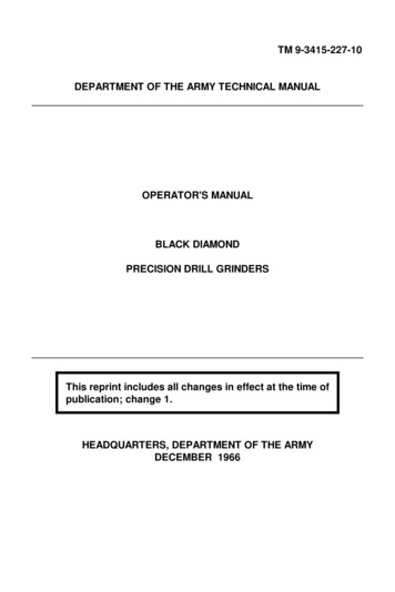
Storms, M. A., Natland, J. H., et al., 1991Proceedings of the Ocean Drilling Program, Initial Reports, Vol. 1328. DIAMOND CORING SYSTEM—ROLLER CONE BITS AND ASSOCIATED HARDWARE1G. L. Holloway2EXECUTIVE SUMMARYDesign changes were made on conventional ODP rotary corebarrel bits to allow deployment with the Diamond Coring System(DCS) hardware. Two of the more significant changes allowed fora latch-in center bit to be run. These changes included: (1) enlarging the throat diameter of the bit and (2) removing the core guidewhile still maintaining the same size roller cones. The center bititself was a completely new design utilizing two small TungstenCarbine Insert (TCI) cones. The position of the center bit withinthe primary bit was adjustable so that the center bit could be runahead of the larger cones or behind them. This was accomplishedby placing spacers between the latch and the center bit. The centerbit was held in place with a modified Extended Core Barrel (XCB)latch which allowed recovery via a wireline.The roller cone bits held up remarkably well against the youngfractured basalt encountered at the Bonin back-arc location.Though not as abrasive as some locations investigated on previoushard rock legs, it still challenged the bits to penetrate and survive.All the holes were spudded with a Positive Displacement CoringMotor (PDCM). Several holes had the additional benefit of beingconfined within the diameter of a casing hanger and run in conjunction with spiral bladed stabilizers. There was no excessivewear or damage reported to any of the larger four-cone bits.Several of these bits were rerun on other holes at the Boninback-arc location. One washout was reported on a center bit after21 hr of rotation. Overall, the bit performance and quality wasrated extremely high.BACKGROUNDOne of the primary objectives of Leg 132 was to provide acased hole to isolate unstable formations in the upper portion ofthe hole and allow the smaller DCS to be deployed. This wasaccomplished by drilling-in and backing a Bottom Hole Assembly(BHA) composed of the larger API drill pipe and/or drill collarsalong with a modified version of ODP's rotary core barrel bit. Inorder to provide a greater degree of flexibility in the drillingprogram, two different sizes of core bits were designed to complement the two sizes of BHA also being developed. It had beenlearned on previous legs that the smaller the hole diameter drilledinto fractured formations, the more likely the hole was to remainstable. However, this fact had to be balanced with the size of theroller cones themselves so that bit life could be preserved.Two bit manufacturers were approached with the idea of redesigning ODP's roller cone bit in order to allow the DCS tubingand core bits to pass. After several discussions with each manufacturer and review of the preliminary concepts presented, Security was chosen to pursue the design to the final stage ofdevelopment.1Storms, M. A., Natland, J. H., et al., 1991. Proc. ODP, Init. Repts., 132: CollegeStation, TX (Ocean Drilling Program).2Ocean Drilling Program, 1000 Discovery Drive, College Station, TX 778459547, U.S.A.Since three locations were to be investigated on this leg, eachwith different types of formation, two cutting structures wereincorporated in the roller bit cones. This allowed a total combination of four types of bits which could be run. It was felt thatwith this selection there was sufficient coverage for any of theformations expected during Leg 132. These formations rangedfrom young fractured basalt to reefal limestones. Figure 1 illustrates the different bit sizes and BHA combination that wereavailable for Leg 132.The conventional bits of this type used by ODP were normallyrun on a core barrel to catch the core cut by the four roller cones.However, for this application where tubing was to be run insidethe API drill pipe and out the bottom of the bit, conventional corebarrel hardware could not be run. Therefore, a whole new BHAand enlarged bit throat were required. To ensure that core wouldnot enter the bit and BHA while drilling in the back-off assembly,the bits had to be further modified to accept a removable centerbit.DESIGN MODIFICATIONSTwo of the more significant design modifications to the bitsmanufactured for Leg 132 included removing the core guide andopening the throat of the bit to a diameter of 4.05 in. Thismodification was required so the diamond coring bits/core barreland tubing string used with the DCS could pass freely out thebottom of the BHA. Several ideas pertaining to the center bitdesign were investigated prior to selecting a wireline retrievablecenter bit. These included: (1) drilling out a welded-in center bit,(2) retrieving a latched-in center bit, and (3) drilling through atri-cone bit with the DCS diamond bit.Before a decision was made as to the direction to pursue in thedesign of the center bit, several attempts were made to drillthrough a conventional core bit and a tri-cone bit with the DCSdiamond bits. Full-scale field tests were performed in Salt LakeCity, Utah, to determine the feasibility of the concept. The resultswere promising but not conclusive. Several diamond bits wereneeded to penetrate completely through existing ODP roller coneor tri-cone bits. It was also felt that the time taken to drill throughthe more conventional bits, coupled with the trip time for the DCStubing and the possibility of leaving inserts, diamond matrix,and/or cones in the hole, was not in the best interest of testing theDCS. This scenario also involved sacrificing several diamond bitsbefore even beginning a hole. Since manufacturing time wasrunning out, it was decided to focus the design on adapting aretrievable center bit using a modified ODP downhole latch assembly.The two sizes of bits manufactured were 11-5/8 and 9-7/8 in.with cutting structures designated as M84F and H87F. The Mdesignation describes bits with tungsten carbide inserts for medium to hard formations. The inserts are shaped for moderateextension with a closely spaced chisel design. The H designatestungsten carbide inserts for hard to extra hard formations. Insertsselected for these bits used a short extension of closely spacedconical design. Both sizes used Securities patented sealed journalbearing and gauge inserts along the shirt-tails with hardfacing on211
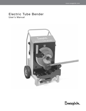
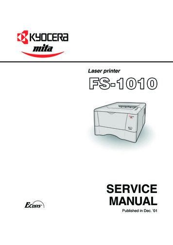
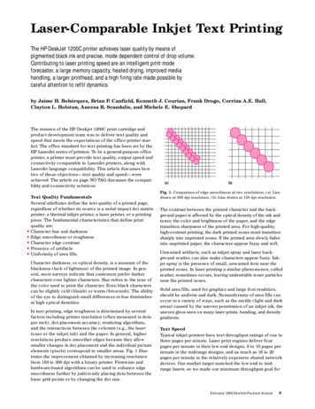
G. L. HOLLOWAYReentry coneMechanicaltensioning toolGimbal deviceMatingreceptacleMini-hard rockguide base \ 1BHA landingseat16 in.casingDCS hydrilstringDCS hydrilstringHard formation conceptSoft formation conceptFigure 1. Bottom hole assembly options.the leading edge. The journal bearing on the larger size bit useda 7-7/8 in. bearing with the smaller size bit using a 6-1/2 in.bearing. A schematic of this type of roller cone bit is presented inFigure 2.CENTER BIT DESIGNSecurity was again selected to pursue the manufacturing of thecenter bit option because of their innovative design, willingnessto work with ODP, and the cost competitiveness of their product.Also, due to the time restraints of manufacturing, it was felt thata single bit manufacturer would be less apt to make dimensionalmistakes or errors in compatibility between the two bit designs.Therefore, along with the large roller cone bits, Security wasto provide the center bits. These bits were to be positioned in thethroat of the larger roller cone bits to provide a cutting structureto remove any material not broken up with the four outer conerollers. Because of the small size required for the center bit, onlytwo cones could be incorporated into this design. A schematicdrawing of the center bit is presented in Figure 3.These bits were made in an assembly which latched into thebladed spiral stabilizers attached immediately above the largerbits. A modified version of the XCB latch was adapted for holdingthe center bits in position (Fig. 4). Besides providing a positivelocking mechanism, the latch also allowed three different lengths212of spacers to be added so that the center bit elevation within thelarger roller cone bits could be changed for the different formations encountered. This allowed for several different combinations of bits to be run until an optimum penetration rate could beestablished for the formation encountered. The elevations were:(1) 1.5 in. behind the roller cones, (2) flush with the roller cones,or (3) 1.5 in. beyond the roller cones. Figure 5 illustrates thedifferent elevations at which the center bit could be positionedwithin the larger roller cone bits. The TCI's used on the smallcenter bits were HI OOF. These inserts were for very hard toabrasive formations with a short 120 double conical shape. Thecenter bit's body was slightly smaller than the cavity providedinside the large bit. Four centralizing tabs approximately oneeighth of the circumference were used to align and prevent wobbleof the center bit inside the throat of the larger roller cone bit. Thesepassageways provided additional flow paths to help in flushingthe face of the center bits. Besides these flow paths, a single 3/16in. hole was provided above each roller cone for the drilling fluidto cool and clean the individual cones.SET-UP/FIELD ASSEMBLYThe assembly of the modified XCB latch and the adaptation tothe two-cone center bits were not without some minor problems,as normally would be expected on any prototype design. These
DIAMOND CORING SYSTEM—ROLLER CONE BITS9.875 in./11.625 in.diameterA-AFigure 2. Roller cone bit design.problems amounted to several small machining errors not checkedbefore the parts were shipped. The first was that the length of theslots in the latch body for the latch dogs had to be increased byapproximately 1 in. in order to latch properly. It was also discovered that the center bits were 3 in. longer than the design calledfor. This made the spacers provided to adjust the position of thecenter bit ineffective. Thus, the center bit without any spacersprotruded from the end of the roller cone bit by approximately1.75 in.It was originally thought that the conditions at the Bonin sitewould necessitate the center bit be recessed. However, it wasdecided not to invest the time to remachine the center bits but torun them as they were originally manufactured. This decisionproved to be correct at least for the unsupported spud-ins, in thatthe center bit acted as a pilot and eliminated the bit skating overthe seafloor. It also provided a more severe test of the center bitlatch assembly and center bit itself. Other than the small omissions mentioned above, the center bit latch assembly workedperfectly. Retrieval of the center bit was effortless on everyattempt made with the overshot.The XCB latch with the center bit attached was required to beloaded into the lower stabilizer before the bit was installed. Thiswas necessary due to fact that the latch had been modified so thatit could only operate in one direction. Loading the center bit wasaccomplished by tens oning the XCB latch first and locking thelatch dogs down with a C-clamp. The bit could be pushed insidethe cavity, oriented, and latched in. The C-clamp would be removed as soon as the latch dogs were held shut by the I.D. of thestabilizer.PERFORMANCEBoreholes 809A And -BTwo test holes were performed at the Bonin back-arc locationto determine the performance of the different size bits. These testswere conducted to evaluate which type bit would provide the bestpenetration rate, hole cleaning characteristics, and stability, andalso retain its integrity in the young fractured basalt expected atthe first location. Both bits were rotated approximately the samelength of time (7 hr for the 11-5/8 in. M84F and 8.25 hr for the9-7/8 in. M84F). However, the actual penetration of the smallerbit nearly doubled that of the larger bit (13.4 m to 8.3 m). It wasgenerally thought that the smaller size bit performed better sincevideo inspection of the seafloor from the VIT revealed a cleanerhole. Also, the torque reported by the driller and stalling of thePDCM was less of a problem than on the first borehole. Resultsfrom the PDCM runs showing weight on bit, flow rate, anddrilling times are presented in Tables 1 and 2. It should be noted,though, that the first borehole was stopped several times in orderto view the spudding and to confirm that the bit was indeedpenetrating the seafloor. This most likely contributed to some fillfalling back into the borehole, confirmed by the amount of redrilling necessary on this borehole each time the PDCM was stoppedfor observation. Another factor is that the two boreholes wereapproximately 100 m apart and, consequently, material variabilitycould have played a much larger role in the changed drillingcharacteristics than the size of the bits. However, it was generallyfelt that the material was consistent over the area.Visual inspection of the roller cone bits and center bits revealed that both bits had very little wear. There were no chippedor broken inserts, all the cones were intact, and the bearingsappeared to still be tight and functional. This was true for boththe center cone bits and the larger roller cone bits despite the factthat the center bits took the majority of the wear by being runahead of the roller cone bit.Boreholes 809C, -D, -E, And -FBoreholes 809C through 809F were all conducted through themini-hard rock guide base (HRB) (Fig. 6) for spudding the DCSholes. All of these BHA's were restrained by the landing seatinside the lower section of the casing hanger (Fig. 7) attached tothe HRB. Also, all the center bits run on these holes were recessed1.5 in. behind the cones of the larger roller bits. Penetration ratesaveraged 10-12 m/hr for Holes 809D and 809F. The drilling ratesfor the two other sites (809C and 809E) were considerably greaterand cannot be grouped into the same category as the other twolocations. This was because a considerable amount of torque didnot reach the bits but was lost by the BHA rotating against theside of the casing hanger. This occurred when attempting to spudand drill the boreholes at an angle greater than the reentry conescould compensate for.The most notable difference between these holes (809Cthrough 809F) and the unsupported spud-in holes (809A and809B) was the penetration rate. Since two of the variables werechanged in the spudding technique, it is not clear how much each213
G. L. HOLLOWAYTop view3.750 in.diameter4.000 in.diameterFigure 3. Center bit design.Latch dogs (2)OP4473Hexagonalhead boltOD7240Modifiedpulling neckOQ2526Landing shoulder capOP4479Washers (2)OQ2524Modifiedlatch bodyOQ2522Figure 4. Modified XCB latch assembly.contributed to the faster drilling. Good arguments can be madefor both. However, it was felt that a significant improvement overbare rock spudding can be realized when the bit is restrained fromrolling around/skating on the seafloor.The two holes drilled at an angle (809C and 809E) and abortedprior to reaching the designated termination depth allowed betterobservation of bit wear. It was observed that material encounteredat the Bonin location was not representative of that expected atEast Pacific Rise or what was found at the Mid-Atlantic Ridge on214Legs 106 and 109. However it is felt that improvements in thesebits over those used previously are a step in the right direction.One of the 11-5/8 in. bits rotated for 21 hr showed little signof wear. However, the accompanying center bit with the samenumber of hours produced a wash out on one of its legs and lossof one insert on the gauge. The other 11-5/8 in. bit was rotatedless than 2 hr and also showed relatively little wear. Typicalweight on bit ranged between 2 and 8 kip. Tables 3 through 7provide the bit record for flow rates, weight on bit, and penetra-
DIAMOND CORING SYSTEM—ROLLER CONE BITSFigure 5. Center bit elevations.Table 1. Coring motor runs, Hole 809A.(1000 67891011121314151617181920aGallons per minute divided by 5 equals strokes per minute.tion. A complete summary of the bits run and their performancein terms of hours run and meters drilled is presented in Table 8.Another important point is that all the bits were manufacturedwith a consistent quality control. Threads were all cut to gaugeon both the larger Hycalog threads and the smaller and moredifficult ODP CX thread on the center bits. There were no reported bearing failures on any of the bits other than the center bit,which experienced a wash out and all the welds held up withoutlosing any arms.Table 2. Coring motor runs, Hole 10065507050710Gallons per minute divided by 5 equals strokes per minute.215
G. L. HOLLOWAYSide viewFigure 6. Mini-hard rock guide base.216
DIAMOND CORING SYSTEM—ROLLER CONE dingseat16 in.buttressthreadKLandingseat keyrestraintRotational. restraints12 in. I.D.15.125 in.21.75 in.Mini-HRB typeReentry cone typeFigure 7. Modified casing hanger.HOLE 810DA 9-7/8 in. H87F bit was run at this location. The formationconsisted of soft calcarious oozes to firmer chalk down to a depthof 127.1 mbsf (417 ft). A hard chert layer was located at this depth.This was confirmed by a wash-in test (no rotation) conductedearlier at this site to determine the depth to which it would bephysically practical to set 16 in. casing. The test, which limitedthe weight on bit to only 5000-10,000 lb, produced a penetrationof 60 m (197 ft) in a little less than an hour. A reentry cone wasthen deployed at this site to establish a conduit for the BHA to bedrilled through (Fig. 8). However, due to a problem with thecasing hanger itself, casing was not run. Since casing was not run,it was decided to drill the BHA (consisting only of drill collars)to 112.63 mbsf (369 ft). This was accomplished in a little less than3 hr with the PDCM. However, because the BHA did not back off217
G. L. HOLLOWAYTable 5. Coring motor runs, Hole 809E.Table 3. Coring motor runs, Hole 809C.Flowrate enetrationno.WOB(1000 3512501300133013451410Gallons per minute divided by 5 equals strokes per minute.Table 4. Coring motor runs, Hole 809D.Runno.WOB(1000 lb)Flowrate 125shut down pumpspull out of 370639064406470649065106570708Comments: Good run, drilled to total depth, and backed off as designed.aGallons per minute divided by 5 equals strokes per minute.as it was suppose to, it was retrieved for inspection. This scenariooccurred two more times before actually leaving the BHA in theseafloor.As would be expected for this soft of material, the bit stilllooked new after being retrieved. There was no damage to theinserts or cones, even though some small stringers of chert mayhave been encountered during the drilling. The center bit, thoughhaving been run twice before in basalt, did not show any additional wear after drilling/washing another 119.3 m (391 ft). Thebit was redeployed a third time and drilled another 13.72 m (45.65ft) where the BHA was finally backed off. However, due to aproblem with the C-ring on the back-off sub, the BHA did notlatch-in but continued downward approximately 26 m (85 ft)deeper than it was supposed to land. This necessitated a fishingtrip to retrieve the BHA. Upon recovery to the rig floor, it wasobserved that the bit was totally destroyed after falling onto thehard chert layer with 50,000 lb of BHA behind it. The weld onone arm had broken and allowed it to be pulled from its originalsocket. The other three arms were broken at the bit body. Theimpact was so severe that even the throat of the bit was deformedand slightly flattened on one side. What was surprising was thatthe center bit again came out without any appreciable additionalwear over the previous run. It is speculated that due to its positionwithin the larger bit (1.5 in. behind the larger cones), the majorityof the impact was taken by the four cones/arms. A record of bitperformance while using the PDCM is provided in Table �————1000—Runno.WOB(1000 2030Comments: Penetration rate decreased to almost nothing, decision made to pullout BHA and check bits.Gallons per minute divided by 5 equals strokes per minute.b10 bbl high viscosity mud pumped down.c10 bbl high viscosity mud pumped down.d15 bbl high viscosity mud pumped down.ePenetration rate decreased significantly.fProblems with stalling out and drag (over pull).g15 bbl high viscosity mud pumped down.hPulling back to keep motor running.1Pulling back to keep motor running.j Motor stalls out with very little WOB.kReestablish rotation.IStall out at 5 gpm, pull back to restore rotation.mReestablish rotation.n50 kip overpull to free BHA.0Good rotation.pMotor stalling out.q10 bbl high viscosity mud pumped down.rMotor stalling out, pick up BHA 0.2 m.a
DIAMOND CORING SYSTEM—ROLLER CONE BITSTable 7. Coring motor runs, Hole 810D.Table 6. Coring motor runs, Hole 809F.Runno.WOB(1000 lb)Flowrate 90700Comments: Pressure spikes not real obvious, but dropped off to 300 psiafter back off.aGallons per minute divided by 5 equals strokes per minute.RECOMMENDATIONS/CONCLUSIONSPerformance of the roller cone bits, center bits, and latchassemblies illustrated that the concept of a removable center bitwas a viable alternative when an additional tubing string was tobe deployed through the initial drilled-in BHA. Though possiblynot as demanding as some young fractured basalt formations, theBonin site did provide several instances where total rotating hoursexceeded that accomplished during Legs 106 and 109. It wasreported not uncommon for bit failure to occur within 6 hr inunsupported bare rock spud-in on Leg 106 and up to 12 hr for thebits used on Leg 109. Designs incorporated from those bits wereused as the basis for the bits manufactured for Leg 132. Better bitlife could also possibly be attributed to overall bit and bearingassembly design, better control of the PDCM, less weight on thebit, better stabilization/centralization, and/or manufacturer/vendor quality control.It was felt that the reduced hole diameter and annulus with the9-7/8 in. bit improved hole stability and hole cleaning characteristics over that of the larger 11-5/8 in. bit. However, with onlytwo tests for comparison, definitive answers can not be claimedat this time. It is recommended that additional testing of the bitsin a similar material be performed so that conclusive evidence cansupport this premise.The two-cone center bits provided a prototype design whichmay be improved after further studying their performance. Sincethese small bearing bits are more apt to wear out sooner than thelarger cone bearings, a more robust design should be investigatedalong with a possible wireline replaceable version, when the holeis not initially drilled with the PDCM. Using the center bit as apilot for bare rock spud-in appeared to prevent the bit fromwalking on the seafloor and may possibly have reduced the wearon the larger cones by removing the initial core. However, prolonged use in this mode could result in the complete failure andpossible loss of the smaller cones.The fact that the BHA was somewhat supported and centralized by the hard rock guide base on Leg 109 was cited as reasonfor longer bit life and performance over what was experienced onLeg 106. This concept was taken a step further using the techniqueof continual centralization and stabilization of the bit until 3031323334353637383940414243444546WOB(1000 lb)Flowrate -20-20-2Penetration(m)—75-10075-10075-100from 0427 to 0431 made up pipe 000-5100-125100-2000-5100-125150-250from 0414 to 0448 made up pipe 25125125—200-225150-225300140-150250-300from 0457 to 0503 made up pipe rom 0511 to 0524 made up pipe -4006-10from 0540 to 0545 made up pipe 00-400from 0553 to 0610 made up pipe 6-8from 0623 to 0632 made up pipe connectionfrom 0632 to 0635 made up pipe 10shut 62306320635063806400641—Gallons per minute divided by 5 equals strokes per minute.hole termination depth was reached on the hard rock sites. Therestrained bit movement due to the tight diameter of the landingseat inside the casing hanger, coupled with the centralization fromthe spiral-bladed stabilizers, is felt to have added significantly tothe bit life and performance. A schematic of the spudding technique is illustrated in Figure 9. Annular clearance through the 12in. landing seat between it and the BHA was typically less than1/2 in. throughout the drilling process. Annular clearances for theHRB used on Leg 109 were much larger due to the 31 in. diameteropening in the guide base despite the fact that a 24 in. diameterguide bushing was run when spudding the hole.Another possible reason for better bit performance was thedifferent design philosophy used to establish the hole. Leg 109attempted to use the more conventional oilfield approach ofdrilling a larger hole and setting surface casing strings, whereasa drill-in type BHA was used on Leg 132. This concept of the219
G. L. HOLLOWAYTable 8. Summary of bit performance.NumberBit 89660489661489662489663489664489665489713489713
EXECUTIVE SUMMARY Design changes were made on conventional ODP rotary core barrel bits to allow deployment with the Diamond Coring System (DCS) hardware. Two of the more significant changes allowed for a latch-in center bit to be run. These changes included: (1) enlarg-ing the t