Transcription
NationalUrban Search & Rescue (US&R)Response SystemRESCUEFIELD OPERATIONS GUIDEUS&R-23-FG
RESCUE FIELD OPERATIONS GUIDE (ROG)The Federal Emergency Management Agency (FEMA) identifies four levelsof operational guidance for use by emergency teams and other personnelinvolved in conducting or supporting disaster operations. This documentcorresponds to the level highlighted in bold italics.Level 1Level 2Level 3Level 4Overview: A brief concept summary of a disaster-relatedfunction, team, or capability.SOP: A complete reference document detailingthe procedures for performing a single function(Standard Operating Procedure), or a number ofinterdependent functions (Ops Manual).Field Operations Guide (FOG ): A durablepocket guide, containing essential nuts-and- boltsinformation needed to perform specificassignments or functions.Job Aid: A checklist or other aid for job performance orjob training.This document is consistent with and supports the Federal Response Planfor implementation of the Robert T. Stafford Disaster Relief and EmergencyAssistance Act, 42 U.S.C. § 5121, et seq.The most current copy of this document, including any change pages, isavailable through the FEMA Intranet in the National Emergency ManagementInformation System (NEMIS) Reference Library (http://nemis.fema.net),under Response and Recovery/Policies and Guidance, Disaster OperationsGuidance.15 Sep 2006US&R-23-FG1
FOREWORDThis Rescue Field Operations Guide has been prepared to guideDepartment of Homeland Security (DHS)/Federal EmergencyManagement Agency (FEMA) Rescue personnel during Federaldisaster response operations.The National Urban Search and Rescue (US&R) ResponseSystem provides for the coordination, development, andmaintenance of the Federal effort with resources to locate,extricate, and provide immediate medical treatment to victimstrapped in collapsed structures; and to conduct other life savingoperations.This guide is designed to supplement the National US&RResponse System Field Operations Guide, September 2003(US&R-23-FG) which provides the US&R Response Systemmethods of operation, organization, capabilities, and procedures inmobilization, on-site operations, and demobilization.This guide provides a detailed reference for performing RescueOperations. The content further elaborates on the content initiallyprovided in US&R-23-FG.Questions, comments, and suggested improvements related to thisdocument are encouraged. Inquiries, information, and requests foradditional copies should be directed in writing to the Department ofHomeland Security, Federal Emergency Management Agency,Response Division, Operations Branch, 500 C Street SW,Washington, DC 2047215 Sep 2006US&R-23-FG2
Introduction:The Department of Homeland Security (DHS), FederalEmergency Management Agency (FEMA), developed theNational Urban Search & Rescue (US&R) Response Systemto support the Emergency Support Function (ESF) #9(Urban Search and Rescue) of the Federal Response Plan.Within this framework, resources are mobilized to respond tostructural collapse and other incidents nationwide.Document Purpose:This DHS/FEMA US&R Rescue Operations Guide has beendeveloped to support response resources during trainingand on missions. This guide supplements the NationalUrban Search and Rescue Response System FOG,September 2003 (US&R-2-FG). This guide is a compilationand summary of important strategic and tactical information,developed procedures, and reference material specificallyfor the performance of Rescue Operations.15 Sep 2006US&R-23-FG3
Table of Contents1.2.3.4.5.Onsite Information1.Personnel Assignments2.Radio Channels3.Team Briefing Components4.Squad POA RequirementsPosition Duties1.RTM General Duties2.RTM On Site Duties3.RSO General Duties4.RSO On Site Duties5.BlankMedevac Procedures1.Medevac Procedures2.Helicopter Hand Signals3.NATO Phonetic AlphabetBOO onsibilities5.Setup Procedures6.Cache Procedures7.TFCP Procedures8.Medical Procedures9.Shelter Procedures10.Sanitation/Hygiene Procedures11.Community Tent Procedures12.Security/Hazards Procedures13.Tent Assignments14.Sample LayoutRECON/Marking Systems1.Strategic, Management & Search Markings2.Search & Recon Initial Tasks3.Structure ID4.FEMA Structures/Hazards Marking5.FEMA Search Assessment Marking6.FEMA Victim Location Marking7.INSARAG Structure Assessment Marking8.INSARAG Victim Location Marking9.Recon Team Make-Up10.Recon Operations11.Site Assessment Forms15 Sep 2006US&R-23-FG2-12-22-32-43-13-2 & 33-43-53-64-1 & 5-146-16-26-3 & 46-56-6 & 76-86-96-106-116-126-13 & 144
Table of Contents (cont.)6.8.9.10.Rescue1.“LCES”2.Weight, Anchors & Bolting3.Sling Angles4.Sling Arrangements and Safe Working Loads5.Crane Signals6.Cribbing7.Shore ExamplesWindow/Door ShoreWindow/Door Prefab ShoreTemporary “T” ShoreDouble “T” ShoreVertical ShoreLace Post ShoreHorizontal ShoreFlying Raker ShoreSplit Sole Raker – U-Channel BaseSplit Sole Raker – Trough BaseSolid Sole Raker45 Degree Raker Strut Lengths60 Degree Raker Strut LengthsRaker Shore Lacing and BracingSloped Floor Shore Perpendicular Type ISloped Floor Shore Perpendicular Type IISloped Floor Shore FrictionGusset Plate, Lacing & Bracing Nail PatternsCleat Nail PatternsSplit Sole Raker Base AlternativesActivity Log Forms (2 sided)Miscellaneous InformationSigns, Symptoms & Treatment for ExposureDirections for Mark I UseEmergency ProceduresGeneral Cordon MarkingsEvacuation Signals15 Sep 47-257-268-1 & 29-19-210-110-25
Personnel AssignmentsRescue Squad:Squad PersonnelOfficer:1(ASL):2:3:4:5:HM:Medic:TFL 1:TFL 2:RTM 1:RTM 2:LOG 1:LOG 2:15 Sep 2006US&R-23-FG1-1
Radio ChannelsTFL 1TFL 2RTM 1RTM 2LOG 1LOG 2MED 1MED 2BOO 1BOO 215 Sep 2006US&R-23-FG1-2
Team Briefing ComponentsSituation / Hazard Evaluation:Operational Period Objectives:Site Control / Required PPE:Logistical Support:Emergency Signals / Procedures:EMS Plan:HAZ MAT Concerns:Communications:Sketch/Notes:15 Sep 2006US&R-23-FG1-3
Squad POA RequirementsSign in/Check inPersonal Pack inspectionVehicle keysContact Information sheetFamily Support Team information sheetMedical review/Shot RecordMRE/WaterCommunications equipment issuePassport (if required)Brief Relief issue15 Sep 2006US&R-23-FG1-4
Rescue Team ManagerGeneral DutiesReports to TFLProvide input to assist the TFL indeveloping the tactical objectivesCoordinate and supervise operationsnecessary to achieve the tactical objectivesDetermine logistical and organizationalneedsReceive briefings and SITREPs from TFLBrief assigned personnelProvide situation updates and maintainreportsPrepare evaluations for assigned personnel15 Sep 2006US&R-23-FG2-1
Rescue Team ManagerOn Site DutiesOverall assessment process to determine: Functional requirements Work schedules and rotation periods Adequacy of support facilitiesCoordinate activities with Search & ReconAssist in development of team action planCoordinate objectives and personnelassignmentsEnsure proper worksite setup, control &safetyEvaluate operations and modify as neededEvaluate capacity of resources to completeassignmentOrder additional resources as needed15 Sep 2006US&R-23-FG2-2
Rescue Team ManagerOn site Duties (cont.)Resolve coordination, personnel andcommunication issuesProvide periodic progress reports to the TFLIdentify completion of assignmentsIdentify availability of resourcesSubmit daily reports to PlansEnsure proper information exchange atrelief or demobNotify Logistics of equipment, supply ormaintenance issues15 Sep 2006US&R-23-FG2-3
Rescue Squad OfficerGeneral DutiesReports to Rescue Team ManagerAppoint Assistant Squad Leader (ASL)Implement rescue component of the TeamAction PlanCoordinate and supervise assignedpersonnel at worksitesDetermine organizational and logisticalneedsProvide situation updates and maintainreportsEvaluate and modify rescue tactics andmethods as neededPrepare evaluations for assigned personnel15 Sep 2006US&R-23-FG2-4
Rescue Squad OfficerOn Site DutiesCoordinate logistical requirements withRescue Team Manager and LogisticsDetermine availability of resourcesEvaluate capacity to complete assignmentOrder additional resources as neededMake periodic progress reports to theRescue Team ManagerSubmit daily reports and records to PlansEnsure proper information exchange atrelief or demobNotify Rescue Team Manager of equipment,supply or maintenance issues15 Sep 2006US&R-23-FG2-5
NOTES:15 Sep 2006US&R-23-FG2-6
Medevac ProceduresSelect and Secure Landing Site:Size depends on number and type of aircraftGround slope 15 degreesEnsure surface free of rocks and debrisAvoid dust, sand and snowEnsure ground firm enough to preventaircraft from bogging down duringloading/unloadingAt approach/departure ends, clearly markobstructions that cannot be removedEnsure 10:1 horizontal clearance to verticalobstructionsMark landing/touchdown siteUse smoke, signalman and or lightsWhen dark, mark touchdown point withinverted “Y” composed of four lights15 Sep 2006US&R-23-FG3- 1
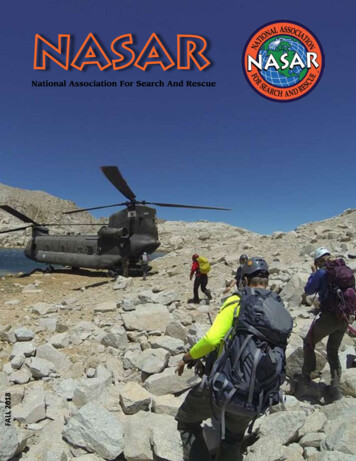
Medevac ProceduresNight Marking of Landing ZonesDirection of FlightLeft Stem14 Meters7 MetersRight StemNote: The touchdown point will be midpoint of thelegs of the “Y”. If more than 1 small aircraft willland, add 1 additional light at the exact point eachis to land. If more than 1 large aircraft will land,add 2 lights placed 10mm apart aligned in thedirection of flight.15 Sep 2006US&R-23-FG3-2
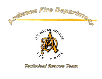
Helicopter Hand Signals15 Sep 2006US&R-23-FG3- 3
NATO Phonetic AlphabetA - AlphaB - BravoC - CharlieD - DeltaE - EchoF - FoxtrotG - GolfH - HotelI - IndiaJ - JulietK - KiloL - LimaM - Mike15 Sep 2006N - NovemberO - OscarP - PapaQ - QuebecR - RomeoS - SierraT - TangoU - UniformV - VictorW - WhiskeyX - X-rayY - YankeeZ - ZuluUS&R-23-FG3-4
BOO Site RequirementsPreferred Size 200x200ft (61x61m)Minimum size 110x150ft (33.5x46m)Cultural/social considerationsAccess to work sitesRunoff/floodingNoise considerationsUtilitiesDamaged structuresPrevailing winds/air hazards15 Sep 2006US&R-23-FG4- 1
BOO Setup PrioritiesTaskCache setup and organizationTask Force Command CenterMedicalPersonnel SheltersSanitation/HygieneCommunity TentCanine ShelterSecurity/Hazards (constant)15 Sep 2006US&R-23-FGPriority1111233N/A4-2
BOO Setup AssignmentsSquad 1:Assigned to tentSquad 2:Assigned to tentPersonnel Shelter setup (Priority 1)Squad 3:Assigned to tentCache setup & organization (Priority 1)Squad 4:Assigned to tentCache setup & organization (Priority 1)15 Sep 2006US&R-23-FG4- 3
BOO Setup ResponsibilitiesSite Requirements (Immediate) Task Force Leader, Rescue Team Manager, LogChief & Comm SpecialistsCache Setup and Organization (Priority 1) Log Chief, Log Specialists, Squads 3 & 4TFCC Setup (Priority 1) Task Force Leader, Plans Chief, CommSpecialists, Technical Info Specialist & SafetyMedical Treatment Area Setup (Priority 1) Medical Manager & Medical SpecialistsPersonnel Shelter Setup (Priority 1) Squad 2Sanitation/Hygiene Issues (Priority 2) SafetyCanine Exercise Area (Priority 3) Search Team Manager & Canine SpecialistsCommunity Tent Setup (Priority 3) Log Chief & Technical Info Specialist15 Sep 2006US&R-23-FG4-4
BOO Setup ProceduresPreferred Size, 200x200ft (61x61m)Minimum Size, 110x150ft (33.5x46m)Utilize Advance Team Kit 2 - 100ft tapes, roll fireline tape, BOO signs,digital camera, vests, chalk, binoculars & paintLayout and identify sections with signs andfireline tapeEntrance should be adjacent to main access ortravel routeMark ground for location, dimension andspacing of each section and tentIdentify travel/access routes Ensure fireextinguishers and signs are presentGenerators placed on perimeter near section tobe poweredIdentify remote fuel storage areaPost signs for all sections and each tent15 Sep 2006US&R-23-FG4- 5
BOO Setup (Cache) ProceduresSize (approximately) 50x60ft (15x18m)Layout/mark Cache area adjacent to BOOentrance and main travel/accessPost conspicuous signMark perimeter with fireline tape and establishentry control pointMark location/layout for cache setup 4 rows Rescue 1 row Technical 1 row WMD (as needed) 1 row LogisticsErect 19x35ft Western Shelter tent for weathersensitive equipment and officeProvide electricity and lightIdentify empty boxes for counter space/seatingProvide tarps/sheeting for weather/security15 Sep 2006US&R-23-FG4-6
BOO Setup (TFCP) ProceduresSize (approximately) 40x30ft (12x9m)Mark perimeter with fireline tape and post signIdentify high ground/elevated structures forcommunicationsErect 2 19x19ft Western Shelter tentsProvide electricity and lightRetrieve/setup all office supplies and formsEstablish the following: Command and Control Workspace Communications Equipment setup Plans/Technical Information workspace15 Sep 2006US&R-23-FG4- 7
BOO Setup (Medical) ProceduresSize (approximately) 25x50ft (7.5x15m)Mark perimeter with fireline tape and post signErect 19x35ft Western Shelter tentProvide electricity and lightEstablish the following: Patient treatment area, with privacy Acute care equipment Office workspace with shelving and seating15 Sep 2006US&R-23-FG4-8
BOO Setup (Shelter) ProceduresSize (approximately) 80x110ft (24x33.5m)Mark perimeter with fireline tape and post signErect Personnel Shelter tentsProvide electricity and lightingProvide smoke & carbon monoxide detectorsand fire extinguishersAffix identification signs to tentsConsider weather and runoff issues15 Sep 2006US&R-23-FG4- 9
BOO Setup (Sanitation/Hygiene) ProceduresSize (approximately) 25x25ft (7.5x7.5m)Mark perimeter with fireline tape and post signSetup a minimum of 4 “Brief Relief” stationsProvide lightingSet up hand washing and or wet wipe stationsPlace trash receptacles throughout BOO(segregate food scraps)Setup up Gross decon station at BOO entrypointsRequest trash collection from local resourcesCollect and dispose of trash 2x daily (segregatefood scraps)Request “Port-A-Potties” from local resources15 Sep 2006US&R-23-FG4 - 10
BOO Setup (Community Tent) ProceduresSize (approximately) 25x35ft (7.5x10.5m)Mark perimeter with fireline tape and post signErect 19x35ft Western Shelter tentProvide electricity and lightingEstablish seating/eating areaEstablish hand washing/clean up areaSetup up task force bulletin boards15 Sep 2006US&R-23-FG4- 11
BOO Setup (Security/Hazards) ProceduresIdentify/Mark Hazards within or adjacent to theBOOIsolate fuel storageProvide fire extinguisher at fuel storage andrefueling locationsPost “No Smoking” signs as appropriateCover cache, supplies and equipment asappropriateRequest additional generators/lighting forimproved safety/securityPost and announce plan for evacuation andassembly pointsIdentify availability of local police/military15 Sep 2006US&R-23-FG4 - 12
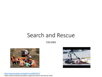
BOO Setup Tent AssignmentsAssignmentTentTFL, RTM, Safety, Plans, TIS ENGTFL, RTM, Safety, Plans, TIS ENGSquad 3 & HM SpecialistSquad 1 & HM SpecialistSquad 4 & Driver/MechanicSquad 2 & Driver/MechanicCanine Specialists & CaninesSTM, Search Specs. & HER Spec.Non-Task Force PersonnelMedical PersonnelCommunications PersonnelLogistics PersonnelABCDEFGHIMedicalCommLog15 Sep 2006US&R-23-FG4- 13
Tent Assignments and Sample tWashHead &ShowerWashMedicalAIBHCGD15 Sep 2006EUS&R-23-FGF4 - 14
Strategic ConsiderationsThe most effective rescue strategy should blend all viable tacticalcapabilities into a logical plan of operation. The general strategicconsiderations are outlined as follows:Rescue Site Management and CoordinationEach rescue work site must have one person in charge to maintainunity of command. The Rescue Squad Officer of each rescuesquad is responsible for all activities of the assigned rescue siteincluding safety when a single squad operates alone. At large orcomplex rescue operations that require the commitment of two ormore rescue squads to a single operation, the Rescue TeamManager may assume command or assign one of the RescueSquad Officers to be in charge of the site. A Safety Officer shouldbe identified at each rescue site.Search PhasesThere are generally five phases of organized search and rescueoperations at collapse incidents:Phase One: Assessment of the collapse area.Phase Two: Removal of all surface victims as quickly andsafely as possible.Phase Three: Search and rescue of victims from accessiblevoid spaces.Phase Four: Selected debris removal to locate and rescuevictims.Phase Five: General debris removal. Usually conducted afterall known victims have been removed.15 Sep 2006US&R-23-FG5- 1
Recon Initial TasksArea sketch/map and building ID (if no structuretriage)Structural/Hazard evaluation and markingBuilding sketch/plan, include building crosssectionBuilding type/configuration, include size &storiesBuilding occupancy typeCollapse typeVoid locationsHazard locationsBest accessHazard mitigation notes15 Sep 2006US&R-23-FG5-2
Structure IdentificationIf no numbers known, use low #’s900 902 904 906 908800900Block Alpha Street1000901 903 905 907 90915 Sep 2006US&R-23-FG5- 3
Structure Identification (Cont.)Side IDCDBAFrontQuadrant IDQuad CQuad BQuad EQuad AQuad DFrontFloor IDFloor 3Floor 2Floor 1Basement 1Basement 2Basement 315 Sep 2006(Use arrow to designatebest entry point)US&R-23-FGGround Level5-4
FEMA Structures/Hazards Marking 2x2ft (60x60cm) Structure relatively safe forUS&R operations Structure significantlydamaged Shoring/removal ofhazards may be required Structure not safe fornormal US&R operations Extensive safety measuresmust be taken before entry15 Sep 200628 JUN 03NATURAL GAS1432HRSNE-TF1 To right of box: Date Hazards Time TF IDUS&R-23-FG5- 5
FEMA Search Assessment Marking Single slash upon entryinto structure TF ID, date & entry timenoted Indicates ongoing 0RATS8L3D18SEP002130PA-TF118SEP001800RATS Crossing slash upon exit Upon exit, date and timenoted in top field Additional informationplaced in open areas of “X” Right - hazards Bottom - # of victims8L3D18SEP002130PA-TF118SEP001800RATS8L3D15 Sep 2006 When new searchcompleted, cross outprevious, and completenew search assessmentmarkingUS&R-23-FG5-6
FEMA Search Assessment MarkingIncomplete Search Marking18SEP002130PA-TF118SEP001800RATS8L3DF 1- 4F 5 Q A/BorNo Entry15 Sep 2006 When search terminatedprior to completion: Place filled circle atcenter of slash Add date & time searchterminated in top field Note hazards to right Note victims beneath Place box below slash,& Note areas searched Use “F” to ID floorssearched Use “Q” to IDquadrants searched If only searchedExterior, as in Hurricane,write “No Entry” in boxUS&R-23-FG5- 7
FEMA Victim Location MarkingCA-TF2VVVVCA-TF22CA-TF25’ “V” indicates potentialvictim location Arrow may be used topinpoint location, adddistance on arrow.Line through “V” indicates confirmed deceased victim.If more than one, marktotal number under V. Circle around “V”indicates confirmed livevictim. If more than one,mark number under V.2CA-TF2 Cross out marking whenvictim is removed.215 Sep 2006US&R-23-FG5-8
INSARAG Structure Assessment MarkingHazard informationNumberof livevictimsremovedG or N(Go/No Go)Team IDNumberof deadvictimsremovedTime/Date of startTime/Date of endPersons unaccounted for:Location of other victims:*When operation is completed, the boxis circled.15 Sep 2006US&R-23-FG5- 9
INSARAG Victim Location MarkingVVVVL-4D-3L-4D-315 Sep 2006“V” near location of knownor potential victimsBelow “V”:Place “L” & # to denotelive victimsPlace “D” & # todenote dead victimsDraw arrow to pinpointconfirmed victimConfirmation must bevisual or audible, caninecannot confirmCircle marking when lastlive victim is removed orplace line through “V”when only dead victimsremainUS&R-23-FG5 - 10
Recon Team Make-UpSearch Team ManagerTechnical Search SpecialistStructures SpecialistMedical Specialist2 Canine Search TeamsHaz-Mat Specialist2 Rescue Specialists15 Sep 2006US&R-23-FG5- 11
Recon OperationsIdentify buildingsStructure/hazards markingArea/building searchSearch/assessment markingAssess void space and atmosphericconditionsVictim location identificationSketch search area and record informationCommunicate findings to appropriatemanager15 Sep 2006US&R-23-FG5 - 12
Site AssessmentDate:Time:Site#:Type of Occupancy:GPS:# of levels:Above ground:Below ground:Possible # of victims/location:Hazards:Utilities controlled:ElectricityGas15 Sep 2006US&R-23-FGWaterOther5- 13
Other assets on site:Witness reports/Intel/Notes:Sketch:15 Sep 2006US&R-23-FG5 - 14
Site AssessmentDate:Time:Site#:Type of Occupancy:GPS:# of levels:Above ground:Below ground:Possible # of victims/location:Hazards:Utilities controlled:ElectricityGas15 Sep 2006US&R-23-FGWaterOther5- 13
Other assets on site:Witness reports/Intel/Notes:Sketch:15 Sep 2006US&R-23-FG5 - 14
Site AssessmentDate:Time:Site#:Type of Occupancy:GPS:# of levels:Above ground:Below ground:Possible # of victims/location:Hazards:Utilities controlled:ElectricityGas15 Sep 2006US&R-23-FGWaterOther5- 13
Other assets on site:Witness reports/Intel/Notes:Sketch:15 Sep 2006US&R-23-FG5 - 14
Site AssessmentDate:Time:Site#:Type of Occupancy:GPS:# of levels:Above ground:Below ground:Possible # of victims/location:Hazards:Utilities controlled:ElectricityGas15 Sep 2006US&R-23-FGWaterOther5- 13
Other assets on site:Witness reports/Intel/Notes:Sketch:15 Sep 2006US&R-23-FG5 - 14
Site AssessmentDate:Time:Site#:Type of Occupancy:GPS:# of levels:Above ground:Below ground:Possible # of victims/location:Hazards:Utilities controlled:ElectricityGas15 Sep 2006US&R-23-FGWaterOther5- 13
Other assets on site:Witness reports/Intel/Notes:Sketch:15 Sep 2006US&R-23-FG5 - 14
Site AssessmentDate:Time:Site#:Type of Occupancy:GPS:# of levels:Above ground:Below ground:Possible # of victims/location:Hazards:Utilities controlled:ElectricityGas15 Sep 2006US&R-23-FGWaterOther5- 13
Other assets on site:Witness reports/Intel/Notes:Sketch:15 Sep 2006US&R-23-FG5 - 14
Site AssessmentDate:Time:Site#:Type of Occupancy:GPS:# of levels:Above ground:Below ground:Possible # of victims/location:Hazards:Utilities controlled:ElectricityGas15 Sep 2006US&R-23-FGWaterOther5- 13
Other assets on site:Witness reports/Intel/Notes:Sketch:15 Sep 2006US&R-23-FG5 - 14
Site AssessmentDate:Time:Site#:Type of Occupancy:GPS:# of levels:Above ground:Below ground:Possible # of victims/location:Hazards:Utilities controlled:ElectricityGas15 Sep 2006US&R-23-FGWaterOther5- 13
Other assets on site:Witness reports/Intel/Notes:Sketch:15 Sep 2006US&R-23-FG5 - 14
Site AssessmentDate:Time:Site#:Type of Occupancy:GPS:# of levels:Above ground:Below ground:Possible # of victims/location:Hazards:Utilities controlled:ElectricityGas15 Sep 2006US&R-23-FGWaterOther5- 13
Other assets on site:Witness reports/Intel/Notes:Sketch:15 Sep 2006US&R-23-FG5 - 14
Site AssessmentDate:Time:Site#:Type of Occupancy:GPS:# of levels:Above ground:Below ground:Possible # of victims/location:Hazards:Utilities controlled:ElectricityGas15 Sep 2006US&R-23-FGWaterOther5- 13
Other assets on site:Witness reports/Intel/Notes:Sketch:15 Sep 2006US&R-23-FG5 - 14
Site AssessmentDate:Time:Site#:Type of Occupancy:GPS:# of levels:Above ground:Below ground:Possible # of victims/location:Hazards:Utilities controlled:ElectricityGas15 Sep 2006US&R-23-FGWaterOther5- 13
Other assets on site:Witness reports/Intel/Notes:Sketch:15 Sep 2006US&R-23-FG5 - 14
Site AssessmentDate:Time:Site#:Type of Occupancy:GPS:# of levels:Above ground:Below ground:Possible # of victims/location:Hazards:Utilities controlled:ElectricityGas15 Sep 2006US&R-23-FGWaterOther5- 13
Other assets on site:Witness reports/Intel/Notes:Sketch:15 Sep 2006US&R-23-FG5 - 14
LCESLookouts Appoint site Safety Officer Observe onlyCommunications Request radio channel(s) Review evacuation signalsEscape Routes Pre-established path to safe areaSafe Zones Pre-established areas of refuge Pre-identified assembly area15 Sep 2006US&R-23-FG6- 1
Weights of Common Building Materials Reinforced Concrete Slabs150 pcf (67kg) Masonry125 pcf (56kg) Wood35 pcf (15kg) Steel490 pcf (220kg) Concrete or Masonry Rubble10 psf (4kg perinch of depth)Anchors and Bolting Minimum edge distance Minimum spacing6x diameter of bolt12x diameter of bolt Minimum depth6x diameter of bolt Preferred depth9x diameter of bolt15 Sep 2006US&R-23-FG6-2
Effects of Sling Angles90Degree60Degree45Degree30Degree1000 lbs1000lbs1000lbs1000lbs450 kg450 kg450 kg450 kg500 lbs225 kg575 lbs258 kg707 lbs318 kg1000 lbs450 kgAmount of load on each leg15 Sep 2006US&R-23-FG6- 3
Sling Arrangements andDesign LoadsVertical1xRating15 Sep 2006Basket2xRatingUS&R-23-FGChoker3/4 xRating6-4
CRANE SIGNALS15 Sep 2006US&R-23-FG6- 5
Cribbing4x4 - 6000lbs (2700kg) per full contact point6x6 - 15,000lbs (6750kg) per full contact pointOverlap corners by 4” (10cm)Up to 15 degree slope max. (3 feet in 10 feet)Allowable Height to Width RatiosAll bearing3 to 1Lifting or moving2 to 12 of 4 bearing1.5 to 11 of 4 bearing1 to 115 Sep 2006US&R-23-FG6-6
Window/Door1 - Header1 - Sole plate2 - Posts4 - Pair 2x4 wedges1 – Triangle Gusset3 - Cleats2 - Diagonals15 Sep 2006At least 1” (2.5cm) of headerdepth for each foot ofhorizontal opening spanned.(4x4 minimum)US&R-23-FG6- 7
Window/Door Prefab1 - Header1 - Sole plate2 - Posts5 - Pair 2x4 wedges8 – Triangle Gussets15 Sep 2006At least 1” (2.5cm) ofheader depth for each footof horizontal openingspanned (4x4 minimum)US&R-23-FG6-8
Temporary “T”1 - Header1 - Sole plate1 - Post1 - Pair 2x4 wedges2 – Full-Gusset plates1 – Half-Gusset or Cleat Up to 11 ft (240cm) for 4x4 Up to 16 ft (360cm) for 6x6 3 ft header (90cm) gets12x12 (30x30xcm) gussetplates15 Sep 2006US&R-23-FG6- 9
Double “T”1 - Header1 - Sole plate2 - Posts2 - Pair 2x4 wedges3 – Dbl-Gusset plates 12x24(30x60cm)2 – Half-Gussets or Cleats 15 Sep 2006Up to 12 ft (240cm) for 4x4Up to 18 ft (360cm) for 6x63 ft header (90cm)Post Spacing is 18 to 24inches out to outUS&R-23-FG6 - 10
Vertical1 - Header1 - Sole plate3 - Posts3 - Pair 2x4 wedges5 – Half- Gussets2 – 2x6 DiagonalsMid point brace ifneeded, use 1x6or ¾” x 6” ply strip15 Sep 2006 Post spacing is 1ft per 1in ofheader depth on center (3-4ftor 90-120cm) Overhand of 1ft (30cm) Mid point brace needed for: 4x4 over 8ft (240cm) tall 6x6 over 12ft (360cm) tallUS&R-23-FG6- 11
Laced Post2 - Headers2 - Sole plates4 - Posts8 - Horizontals4 - Pair 2x4 wedges8 - Diagonals8 – Half- GussetsPost spacing is 3 to5 feet (90 to 150cm)1 ft (30cm) overhangLacing/bracing is2x4 for 4x4Lacing/bracing is2x6 for 6x6Add one horizontal &one diagonal to eachside if over 11 ft(330cm) tall15 Sep 2006US&R-23-FG6 - 12
Horizontal Shims go on2 - Wall platesundamaged side3 - Struts3 - Pair 2x4 wedges7 - 4x4 wedges (9 if bottom strut not on floor)1- Half-gusset(or Cleat)2 - Diagonals1 - Cleat15 Sep 2006US&R-23-FG6- 13
Flying Raker1 - Wall Plate1 - Raker strut1 - Cleat2 – Full- Gussets2 - 2x6 Horizontal Braces1 - U Channel Foot1 - Pair 2x4 or 4x4 wedges15 Sep 2006US&R-23-FG6 - 14
Split Sole Raker – U-Channel Base1 - Wall Plate1 - Raker Strut1 - Cleat2 – Full- Gussets2 - 2x6 Horizontal Braces2 - 2x6 Mid Point Braces1 - U Channel1 - Sole Plate1 - Pair 2x4 wedges( 4x4 if needed)U-ChannelSee Page 6- 2615 Sep 2006US&R-23-FG6- 15
Split Sole Raker – Trough Base1 - Wall Plate1 - Raker Strut1 - Cleat2 – Full- Gussets2 - 2x6 Horizontal Braces2 - 2x6 Mid Point Braces1 - Trough Foot1 - Sole AnchSole Anch 6x6x36 (90cm)1 - Pair 2x4 wedges4 - 1” Pickets to soil(4x4 if needed)2 - 1” Pickets to Paving4x4 up to 11 ft (330cm)without mid point bracing6x6 up to 16 ft (480cm)without mid point bracing“X” or “V” bracing ateach end & every 40 feet(13.5m) max.Trough w/ 1” Picket ea sideSee Page 6- 2615 Sep 2006US&R-23-FG6 - 16
Solid Sole Raker1 - Wall plate1 - Sole plate1 - Strut2 - Cleats6 – Full- Gussets2 - 2x6 diagonals1 - Pair 2x4 or 4x4 wedges4x4 up to 11 ft (330cm) withoutmid point bracing6x6 up to 16 ft (480cm) withoutmid point bracing“X” or “V” bracing at each end& every 40 feet (13.5m) max.15 Sep 2006US&R-23-FG6- 17
45 Degree Raker Strut LengthsLong point to long pointInsertion PointFeet8910111213141516171819202122232415 Sep 2006Strut 4869173477782086390795099310366 - 18
60 Degree Raker Strut LengthsLong point to long pointInsertion PointFeet8910111213141516171819202122232415 Sep 2006Strut 335696056406767117477828188536- 19
Raker Shore Lacing and BracingEvery 40 ft (13.5m) and each endInsertion Point4x4 8 ft (330cm)6x6 16 ft (480cm)15 Sep 2006Insertion Point4x4 8 ft (330cm)6x6 16 ft (480cm)US&R-23-FG6 - 20
Sloped Floor ShorePerpendicular - Type IUsed when slope is over 3 degrees(6 inches in 10 feet)Pairs placed up to 8 ft (240cm)Sloped floor/structure must beattached at top or bottom2x6 horizontal & diag. “X” bracing¾” plywood with a min. width of 12”(30cm) and a max. length of 5 ft(152cm), may replace bracing onshort side with a min. of 11 - 8d nailsto each post15 Sep 2006US&R-23-FG1 - Header2 - Posts2 - U Channels2 - 2x6 Diagonals1 - Horizontals2 – Half-gussets2 - U Channels2 - Pair 2x4 wedges2 - Sole plates6- 21
Sloped Floor ShorePerpendicular - Type IIUsed when slope is over 3 degrees(6 inches in 10 feet)Slope pairs placed up to 8 ft (240cm)2x6 horizontal and diag. “X” bracingSloped floor/structure must bea
4. Squad POA Requirements 2-4 2. Position Duties 1. RTM General Duties 3-1 2. RTM On Site Duties 3-2 & 3 3. RSO General Duties 3-4 4. RSO On Site Duties 3-5 5. Blank 3-6 3. Medevac Procedures 1. Medevac Procedures 4-1 & 2 2. Helicopter Hand Signals 4-3 3. NATO Phonetic Alphabet 4-4 4. BOO Setup 1. Requirements 5-1 2. Priorities 5-2 3 .